
PRESTIGE 652HWI - Routeur ADSL ZYXEL - Notice d'utilisation et mode d'emploi gratuit
Retrouvez gratuitement la notice de l'appareil PRESTIGE 652HWI ZYXEL au format PDF.

| Type de produit | Routeur ADSL avec point d'acces Wi-Fi (802.11b) |
| Marque et modele | ZYXEL Prestige 652HWI |
| Dimensions approx. | 20 x 15 x 4 cm |
| Poids approx. | 0,5 kg |
| Alimentation | Adaptateur secteur externe 12V DC |
| Debit ADSL max | Descendant : 8 Mb/s, Montant : 832 kb/s |
| Interfaces LAN | 4 ports Ethernet 10/100 auto-negociation + Wi-Fi 802.11b PCMCIA optionnelle |
| Interfaces WAN | 1 port ADSL (RJ-11) |
| Fonctions principales | NAT, pare-feu Stateful Inspection, VPN IPSec (jusqu'a 10 tunnels), WEP, filtrage MAC, DNS dynamique, UPnP, DHCP serveur, routage IP |
| Securite Wi-Fi | WEP 64/128 bits, filtrage d'adresses MAC, ESSID, authentification 802.1x avec RADIUS |
| Encapsulations ADSL | PPPoE, PPPoA, RFC 1483, ENET ENCAP |
| Multiplexage | VC-based et LLC-based |
| Gestion | Interface web, SMT (terminal), Telnet, FTP, SNMP, CLI |
| Port auxiliaire | CON/AUX pour console et sauvegarde modem (RTC) |
| Fonctions avancees | Redirection de trafic, IP Alias, IP Policy Routing, sauvegarde WAN par modem |
| Logs et diagnostics | Syslog, diagnostics integres, test boucle OAM |
| Mise a jour firmware | Via TFTP/FTP/Xmodem |
| Consommation electrique | Environ 12 W |
FOIRE AUX QUESTIONS - PRESTIGE 652HWI ZYXEL
Questions des utilisateurs sur PRESTIGE 652HWI ZYXEL
0 question sur cet appareil. Repondez a celles que vous connaissez ou posez la votre.
Poser une nouvelle question sur cet appareil
Téléchargez la notice de votre Routeur ADSL au format PDF gratuitement ! Retrouvez votre notice PRESTIGE 652HWI - ZYXEL et reprennez votre appareil électronique en main. Sur cette page sont publiés tous les documents nécessaires à l'utilisation de votre appareil PRESTIGE 652HWI de la marque ZYXEL.
MODE D'EMPLOI PRESTIGE 652HWI ZYXEL
Prestige 652 Series
ADSL Security/Wireless LAN Router
User's Guide
Version 3.40
June 2003
ZyXEL Unleash Network
Unleash Networking Power
Copyright
Copyright © 2003 by ZyXEL Communications Corporation.
The contents of this publication may not be reproduced in any part or as a whole, transcribed, stored in a retrieval system, translated into any language, or transmitted in any form or by any means, electronic, mechanical, magnetic, optical, chemical, photocopying, manual, or otherwise, without the prior written permission of ZyXEL Communications Corporation.
Published by ZyXEL Communications Corporation. All rights reserved.
Disclaimer
ZyXEL does not assume any liability arising out of the application or use of any products, or software described herein. Neither does it convey any license under its patent rights nor the patent rights of others. ZyXEL further reserves the right to make changes in any products described herein without notice. This publication is subject to change without notice.
Trademarks
ZyNOS (ZyXEL Network Operating System) is a registered trademark of ZyXEL Communications, Inc. Other trademarks mentioned in this publication are used for identification purposes only and may be properties of their respective owners.
Federal Communications Commission (FCC) Interference Statement
This device complies with Part 15 of FCC rules. Operation is subject to the following two conditions:
• This device may not cause harmful interference.
- This device must accept any interference received, including interference that may cause undesired operations.
This equipment has been tested and found to comply with the limits for a Class B digital device pursuant to Part 15 of the FCC Rules. These limits are designed to provide reasonable protection against harmful interference in a commercial environment. This equipment generates, uses, and can radiate radio frequency energy, and if not installed and used in accordance with the instructions, may cause harmful interference to radio communications.
If this equipment does cause harmful interference to radio/television reception, which can be determined by turning the equipment off and on, the user is encouraged to try to correct the interference by one or more of the following measures:
- Reorient or relocate the receiving antenna.
- Increase the separation between the equipment and the receiver.
- Connect the equipment into an outlet on a circuit different from that to which the receiver is connected.
- Consult the dealer or an experienced radio/TV technician for help.
Notice 1
Changes or modifications not expressly approved by the party responsible for compliance could void the user's authority to operate the equipment.
Certifications
Refer to the product page at www.zyxel.com.

Tested To Comply With FCC Standards
FOR HOME OR OFFICE USE
ZyXEL Limited Warranty
ZyXEL warrants to the original end user (purchaser) that this product is free from any defects in materials or workmanship for a period of up to two years from the date of purchase. During the warranty period, and upon proof of purchase, should the product have indications of failure due to faulty workmanship and/or materials, ZyXEL will, at its discretion, repair or replace the defective products or components without charge for either parts or labor, and to whatever extent it shall deem necessary to restore the product or components to proper operating condition. Any replacement will consist of a new or re-manufactured functionally equivalent product of equal value, and will be solely at the discretion of ZyXEL. This warranty shall not apply if the product is modified, misused, tampered with, damaged by an act of God, or subjected to abnormal working conditions.
Note
Repair or replacement, as provided under this warranty, is the exclusive remedy of the purchaser. This warranty is in lieu of all other warranties, express or implied, including any implied warranty of merchantability or fitness for a particular use or purpose. ZyXEL shall in no event be held liable for indirect or consequential damages of any kind of character to the purchaser.
To obtain the services of this warranty, contact ZyXEL's Service Center for your Return Material Authorization number (RMA). Products must be returned Postage Prepaid. It is recommended that the unit be insured when shipped. Any returned products without proof of purchase or those with an out-dated warranty will be repaired or replaced (at the discretion of ZyXEL) and the customer will be billed for parts and labor. All repaired or replaced products will be shipped by ZyXEL to the corresponding return address, Postage Paid. This warranty gives you specific legal rights, and you may also have other rights that vary from country to country.
Safety Warnings
- To reduce the risk of fire, use only No. 26 AWG or larger telephone wire.
- Do not use this product near water, for example, in a wet basement or near a swimming pool.
- Avoid using this product during an electrical storm. There may be a remote risk of electric shock from lightening.
Customer Support
Please have the following information ready when you contact customer support.
• Product model and serial number.
• Warranty Information.
• Date that you received your device.
- Brief description of the problem and the steps you took to solve it.
| METHOD/LOCATION | E-MAIL SUPPORT/SALES | TELEPHONE/FAX | WEB SITE/ FTP SITE | REGULAR MAIL |
| WORLDWIDE | support@zyxel.com.twsales@zyxel.com.tw | +886-3-578-3942+886-3-578-2439 | www.zyxel.comwww.europe.zyxel.comftp.europe.zyxel.com | ZyXEL Communications Corp., 6 Innovation Road II, Science-Based Industrial Park, Hsinchu 300, Taiwan. |
| NORTH AMERICA | support@zyxel.comsales@zyxel.com | +1-800-255-4101+1-714-632-0858 | www.us.zyxel.comftp.zyxel.com | |
| SCANDINAVIA | support@zyxel.dksales@zyxel.dk | +45-3955-0700+45-3955-0707 | www.zyxel.dkftp.zyxel.dk | ZyXEL Communications A/S, Columbusvej 5, 2860 Soeborg, Denmark. |
| GERMANY | support@zyxel.desales@zyxel.de | +49-2405-6909-0+49-2405-6909-99 | www.zyxel.de | ZyXEL Deutschland GmbH. Adenauerstr. 20/A2 D-52146 Wuerselen, Germany |
| FINLAND | support@zyxel.fisales@zyxel.fi | +358-9-4780 8400+358-9-4780 8448 | www.zyxel.fi | ZyXEL Communications Oy, Malminkaari 10, 00700 Helsinki, Finland. |
Table of Contents
Copyright......ii
Federal Communications Commission (FCC) Interference Statement......iii
ZyXEL Limited Warranty ......iv
Customer Support......v
List of Figures ......xiv
List of Tables ...... xxi
List of Charts ...... XXV
Preface ....xxvi
What is DSL? ....xxviii
Getting Started....I
Chapter 1 Getting To Know Your Prestige ....1-1
1.1 Introducing the Prestige 652 Series 1-1
1.2 Features of the Prestige....1-1
1.3 Applications for the Prestige....1-6
Chapter 2 Introducing the Web Configurator ....2-1
2.1 Web Configurator Overview....2-1
2.2 Accessing the Prestige Web Configurator 2-1
2.3 Navigating the Prestige Web Configurator 2-2
2.4 Resetting the Prestige....2-3
Chapter 3 Wizard Setup....3-1
3.1 Wizard Setup Introduction....3-1
3.2 Encapsulation....3-1
3.3 Multiplexing....3-2
3.4 VPI and VCI 3-2
3.5 Wizard Setup Configuration: First Screen 3-2
3.6 IP Address and Subnet Mask 3-4
3.7 IP Address Assignment....3-4
3.8 Nailed-Up Connection (PPP) 3-6
3.9 NAT 3-6
3.10 Wizard Setup Configuration: Second Screen....3-6
3.11 DHCP Setup....3-11
3.12 Wizard Setup Configuration: Third Screen....3-12
3.13 Wizard Setup Configuration: Connection Tests....3-14
3.14 Test Your Internet Connection....3-15
Password, LAN, Wireless LAN and WAN ...... II
Chapter 4 Password Setup....4-1
4.1 Password Overview 4-1
4.2 Configuring Password....4-1
Chapter 5 LAN Setup ....5-1
5.1 LAN Overview....5-1
5.2 DNS Server Address 5-1
5.3 DNS Server Address Assignment 5-2
5.4 LAN TCP/IP 5-2
5.5 Configuring LAN 5-4
Chapter 6 Wireless LAN Setup....6-1
6.1 Wireless LAN Overview....6-1
6.2 Levels of Security 6-3
6.3 Data Encryption with WEP 6-4
6.4 Inserting a PCMCIA Wireless LAN Card....6-4
6.5 Configuring Wireless LAN 6-4
6.6 Configuring MAC Filter....6-6
6.7 Network Authentication....6-8
6.8 Configuring 802.1x 6-10
6.9 Configuring Local User Authentication 6-12
6.10 Configuring RADIUS 6-14
Chapter 7 WAN Setup ....7-1
7.1 WAN Overview 7-1
7.2 Metric 7-1
7.3 PPPoE Encapsulation....7-1
7.4 Traffic Shaping....7-2
7.5 Configuring WAN Setup....7-3
7.6 WAN Backup....7-7
7.7 Traffic Redirect on the LAN 7-7
7.8 Traffic Redirect on the WAN....7-8
7.9 Configuring WAN Backup....7-9
7.10 Configuring Advanced WAN Backup 7-12
7.11 AT Command Strings 7-16
7.12 DTR Signal 7-17
7.13 Response Strings 7-17
7.14 Configuring Advanced Modem Setup....7-17
NAT, Dynamic DNS and Time Zone...... III
Chapter 8 Network Address Translation (NAT) Screens....8-1
8.1 NAT Overview....8-1
8.2 SUA (Single User Account) Versus NAT 8-5
8.3 SUA Server 8-6
8.4 Selecting the NAT Mode....8-8
8.5 Configuring SUA Server 8-9
8.6 Configuring Address Mapping....8-11
8.7 Editing an Address Mapping Rule 8-12
Chapter 9 Dynamic DNS Setup 9-1
9.1 Dynamic DNS....9-1
9.2 Configuring Dynamic DNS 9-1
Chapter 10 Time Zone....10-1
10.1 Configuring Time Zone 10-1
Firewall and Content Filters......IV
Chapter 11 Firewalls.... 11-1
11.1 Firewall Overview 11-1
11.2 Types of Firewalls....11-1
11.3 Introduction to ZyXEL's Firewall 11-2
11.4 Denial of Service 11-3
11.5 Stateful Inspection 11-7
11.6 Guidelines For Enhancing Security With Your Firewall 11-11
11.7 Packet Filtering Vs Firewall 11-12
Chapter 12 Firewall Configuration....12-1
12.1 Remote Management and the Firewall 12-1
12.2 Enabling the Firewall....12-1
12.3 Attack Alert 12-2
Chapter 13 Creating Custom Rules ....13-1
13.1 Rules Overview.... 13-1
13.2 Rule Logic Overview....13-1
13.3 Connection Direction....13-3
13.4 Logs 13-4
13.5 Rule Summary 13-4
13.6 Predefined Services....13-6
13.7 Creating/Editing Firewall Rules....13-9
13.8 Timeout....13-12
Chapter 14 Customized Services....14-1
14.1 Introduction to Customized Services 14-1
14.2 Creating/Editing A Customized Service 14-2
14.3 Example Custom Service Firewall Rule 14-3
Chapter 15 Content Filtering Screens....15-1
15.1 Content Filtering Overview 15-1
15.2 Configuring Keyword Blocking....15-1
15.3 Configuring the Schedule 15-3
15.4 Configuring Trusted Computers 15-4
VPN/IPSec V
Chapter 16 Introduction to IPSec....16-1
16.1 VPN Overview....16-1
16.2 IPSec Architecture 16-3
16.3 Encapsulation....16-5
16.4 IPSec and NAT 16-5
Chapter 17 VPN Screens ....17-1
17.1 VPN/IPSec Overview....17-1
17.2 IPSec Algorithms 17-1
17.3 My IP Address....17-2
17.4 Secure Gateway Address....17-2
17.5 VPN Summary Screen 17-3
17.6 Keep Alive 17-5
17.7 ID Type and Content....17-5
17.8 Pre-Shared Key 17-7
17.9 Editing VPN Policies 17-7
17.10 IKE Phases 17-13
17.11 Configuring Advanced IKE Settings....17-14
17.12 Manual Key Setup....17-18
17.13 Configuring Manual Key 17-19
17.14 Viewing SA Monitor....17-22
17.15 Configuring Global Setting 17-24
17.16 Telecommuter VPN/IPSec Examples 17-25
17.17 VPN and Remote Management....17-27
Remote Management, UPnP and Logs...... VI
Chapter 18 Remote Management Configuration....18-1
18.1 Remote Management Overview....18-1
18.2 Telnet 18-2
18.3 FTP....18-2
18.4 Web....18-3
18.5 Configuring Remote Management....18-3
Chapter 19 Universal Plug-and-Play (UPnP)....19-1
19.1 Introducing Universal Plug and Play....19-1
19.2 UPnP and ZyXEL 19-2
19.3 Installing UPnP in Windows Example....19-3
19.4 Using UPnP in Windows XP Example 19-5
Chapter 20 Logs Screens ....20-1
20.1 Logs Overview....20-1
20.2 Configuring Log Settings....20-1
20.3 Displaying the Logs 20-4
20.4 SMTP Error Messages 20-5
Maintenance......VII
Chapter 21 Maintenance ....21-1
21.1 Maintenance Overview 21-1
21.2 System Status Screen 21-1
21.3 DHCP Table Screen 21-6
21.4 Wireless Screens 21-6
21.5 Diagnostic Screens....21-8
21.6 Firmware Screen 21-11
SMT General Configuration......VIII
Chapter 22 Introducing the SMT ...... 22-1
22.1 SMT Introduction 22-1
22.2 Navigating the SMT Interface....22-3
22.3 Changing the System Password 22-6
Chapter 23 Menu 1 General Setup....23-1
23.1 General Setup....23-1
23.2 Procedure To Configure Menu 1 ....23-1
Chapter 24 Menu 2 WAN Backup Setup ....24-1
24.1 Introduction to WAN Backup Setup....24-1
24.2 Dial Backup 24-1
24.3 Configuring Dial Backup in Menu 2....24-1
24.4 Configuring Dial Backup Setup....24-4
24.5 Advanced Dial Backup Setup 24-6
24.6 Remote Node Profile (Backup ISP) 24-8
24.7 Editing PPP Options 24-10
24.8 Editing TCP/IP Options 24-11
24.9 Editing Login Script....24-13
24.10 Remote Node Filter 24-14
Chapter 25 Menu 3 LAN Setup ....25-1
25.1 LAN Setup 25-1
25.2 Protocol Dependent Ethernet Setup 25-2
25.3 TCP/IP Ethernet Setup and DHCP 25-2
Chapter 26 Wireless LAN Setup....26-1
26.1 Wireless LAN Overview....26-1
26.2 Inserting a PCMCIA Wireless LAN Card 26-1
26.3 Wireless LAN Setup 26-1
Chapter 27 Internet Access ...... 27-1
27.1 Internet Access Overview 27-1
27.2 IP Policies 27-1
27.3 IP Alias 27-1
27.4 IP Alias Setup 27-2
27.5 Route IP Setup 27-4
27.6 Internet Access Configuration 27-5
Chapter 28 Remote Node Configuration ....28-1
28.1 Remote Node Setup Overview....28-1
28.2 Remote Node Setup 28-1
28.3 Remote Node Network Layer Options....28-6
28.4 Remote Node Filter 28-8
28.5 Editing ATM Layer Options 28-9
Chapter 29 Static Route Setup....29-1
29.1 IP Static Route Overview....29-1
29.2 Configuration 29-2
Chapter 30 Bridging Setup....30-1
30.1 Bridging in General....30-1
30.2 Bridge Ethernet Setup 30-1
Chapter 31 Network Address Translation (NAT)....31-1
31.1 Using NAT 31-1
31.2 Applying NAT 31-1
31.3 NAT Setup 31-3
31.4 Configuring a Server behind NAT 31-9
31.5 General NAT Examples 31-11
Chapter 32 Enabling the Firewall....32-1
32.1 Remote Management and the Firewall....32-1
32.2 Access Methods 32-1
32.3 Enabling the Firewall 32-1
SMT Advanced Management.... IX
Chapter 33 Filter Configuration....33-1
33.1 About Filtering....33-1
33.2 Configuring a Filter Set for the Prestige 652H/HW 33-4
33.3 Configuring a Filter Set for the Prestige 652....33-6
33.4 Filter Rules Summary Menus....33-7
33.5 Configuring a Filter Rule 33-8
33.6 Filter Types and NAT 33-15
33.7 Example Filter....33-15
33.8 Applying Filters and Factory Defaults 33-18
Chapter 34 SNMP Configuration ....34-1
34.1 About SNMP 34-1
34.2 Supported MIBs 34-2
34.3 SNMP Configuration 34-2
34.4 SNMP Traps....34-4
Chapter 35 System Security ....35-1
35.1 System Security....35-1
35.2 Creating User Accounts on the Prestige....35-5
Chapter 36 System Information and Diagnosis....36-1
36.1 System Status 36-1
36.2 System Information 36-3
36.3 Log and Trace 36-5
36.4 Diagnostic 36-8
Chapter 37 Firmware and Configuration File Maintenance ....37-1
37.1 Filename Conventions 37-1
37.2 Backup Configuration....37-2
37.3 Restore Configuration....37-7
37.4 Uploading Firmware and Configuration Files 37-10
Chapter 38 System Maintenance....38-1
38.1 Command Interpreter Mode....38-1
38.2 Call Control Support 38-2
38.3 Time and Date Setting 38-4
Chapter 39 Remote Management....39-1
39.1 Remote Management Overview....39-1
39.2 Remote Management 39-1
39.3 Remote Management and NAT 39-3
39.4 System Timeout 39-3
Chapter 40 IP Policy Routing ....40-1
40.1 IP Policy Routing Overview 40-1
40.2 Benefits of IP Policy Routing ....40-1
40.3 Routing Policy 40-1
40.4 IP Routing Policy Setup 40-2
40.5 Applying an IP Policy 40-5
40.6 IP Policy Routing Example....40-7
Chapter 41 Call Scheduling ....41-1
41.1 Introduction....41-1
SMT VPN/IPSec and Internal SPTGEN......X
Chapter 42 VPN/IPSec Setup....42-1
42.1 VPN/IPSec Overview 42-1
42.2 IPSec Summary Screen 42-2
42.3 IPSec Setup 42-6
42.4 IKE Setup....42-11
42.5 Manual Setup 42-13
Chapter 43 SA Monitor ....43-1
43.1 SA Monitor Overview....43-1
43.2 Using SA Monitor....43-1
Chapter 44 Internal SPTGEN ....44-1
44.1 Internal SPTGEN Overview 44-1
44.2 The Configuration Text File Format 44-1
44.3 Internal SPTGEN FTP Download Example 44-3
44.4 Internal SPTGEN FTP Upload Example 44-4
Appendices and Index ......XI
Appendix A Troubleshooting......A-1
Appendix B IP Subnetting......B-1
Appendix C Wireless LAN and IEEE 802.11......C-1
Appendix D PPPoE ....D-1
Appendix E Virtual Circuit Topology....E-1
Appendix F Power Adaptor Specifications ...... F-1
Appendix G Example Internal SPTGEN Screens ...... G-1
Appendix H Setting up Your Computer's IP Address...... H-1
Appendix I Splitters and Microfilters ...... I-1
Appendix J Log Descriptions....J-1
Appendix K Index....K-1
List of Figures
Figure 1-1 Prestige Internet Access Application....1-7
Figure 1-2 Firewall Application....1-8
Figure 1-3 VPN Application....1-9
Figure 1-4 Prestige LAN-to-LAN Application....1-10
Figure 2-1 Password Screen 2-2
Figure 2-2 Web Configurator SITE MAP Screen 2-3
Figure 2-3 Example Xmodem Upload....2-4
Figure 3-1 Wizard Screen 1 .... 3-3
Figure 3-2 Internet Connection with PPPoE....3-6
Figure 3-3 Internet Connection with RFC 1483 3-8
Figure 3-4 Internet Connection with ENET ENCAP....3-9
Figure 3-5 Internet Connection with PPPoA 3-10
Figure 3-6 Wizard Screen 3 .... 3-12
Figure 3-7 Wizard : LAN Configuration....3-13
Figure 3-8 Wizard Screen 4 .... 3-14
Figure 4-1 Password ....4-1
Figure 5-1 LAN and WAN IP Addresses ....5-1
Figure 5-2 LAN 5-4
Figure 6-1 RTS/CTS 6-2
Figure 6-2 Prestige Wireless Security Levels 6-3
Figure 6-3 Wireless....6-5
Figure 6-4 MAC Address Filter 6-7
Figure 6-5 EAP Authentication....6-10
Figure 6-6 802.1x....6-10
Figure 6-7 Local User Database ....6-13
Figure 6-8 RADIUS....6-14
Figure 7-1 Example of Traffic Shaping 7-3
Figure 7-2 WAN Setup 7-4
Figure 7-3 Traffic Redirect Setup Example 7-8
Figure 7-4 Traffic Redirect WAN Setup 7-8
Figure 7-5 Traffic Redirect LAN Setup....7-9
Figure 7-6 WAN Backup ....7-10
Figure 7-7 Advanced WAN Backup....7-13
Figure 7-8 Advanced Modem Setup 7-18
Figure 8-1 How NAT Works....8-3
Figure 8-2 NAT Application With IP Alias 8-4
Figure 8-3 Multiple Servers Behind NAT Example....8-8
Figure 8-4 NAT Mode....8-8
Figure 8-5 Edit SUA/NAT Server Set....8-10
Figure 8-6 Address Mapping Rules....8-11
Figure 8-7 Address Mapping Rule Edit....8-13
Figure 9-1 DDNS 9-2
Figure 10-1 Time/Date 10-1
Figure 11-1 Prestige Firewall Application ....11-3
Figure 11-2 Three-Way Handshake....11-5
Figure 11-3 SYN Flood....11-5
Figure 11-4 Smurf Attack....11-6
Figure 11-5 Stateful Inspection....11-8
Figure 12-1 Enabling the Firewall 12-1
Figure 12-2 Attack Alert 12-4
Figure 13-1 LAN to WAN Traffic.... 13-3
Figure 13-2 WAN to LAN Traffic.... 13-4
Figure 13-3 Firewall Rules Summary: First Screen.... 13-5
Figure 13-4 Creating/Editing A Firewall Rule 13-10
Figure 13-5 Adding/Editing Source and Destination Addresses 13-12
Figure 13-6 Timeout.... 13-13
Figure 14-1 Customized Services ...... 14-1
Figure 14-2 Creating/Editing A Customized Service 14-2
Figure 14-3 Configure Source IP Example 14-4
Figure 14-4 Customized Service for MyService Example.... 14-4
Figure 14-5 Syslog Rule Configuration Example 14-5
Figure 14-6 Rule Summary Example.... 14-6
Figure 15-1 Content Filter: Keyword.... 15-2
Figure 15-2 Content Filter: Schedule 15-3
Figure 15-3 Content Filter: Trusted.... 15-4
Figure 16-1 Encryption and Decryption.... 16-2
Figure 16-2 VPN Application 16-3
Figure 16-3 IPSec Architecture.... 16-4
Figure 16-4 Transport and Tunnel Mode IPSec Encapsulation.... 16-5
Figure 17-1 IPSec Summary Fields .... 17-3
Figure 17-2 VPN Summary 17-4
Figure 17-3 VPN IKE 17-8
Figure 17-4 Two Phases to Set Up the IPSec SA.... 17-13
Figure 17-5 VPN IKE: Advanced 17-15
Figure 17-6 Manual Setup.... 17-19
Figure 17-7 SA Monitor.... 17-23
Figure 17-8 Global Setting.... 17-24
Figure 17-9 Telecommuters Sharing One VPN Rule Example 17-26
Figure 17-10 Telecommuters Using Unique VPN Rules Example 17-27
Figure 18-1 Telnet Configuration on a TCP/IP Network .... 18-2
Figure 18-2 Remote Management .... 18-3
Figure 19-1 Configuring UPnP....19-2
Figure 20-1 Log Settings ....20-2
Figure 20-2 View Logs ....20-4
Figure 20-3 E-mail Log Example ......20-6
Figure 21-1 System Status....21-2
Figure 21-2 System Status: Show Statistics....21-4
Figure 21-3 DHCP Table 21-6
Figure 21-4 Association List....21-7
Figure 21-5 Channel Usage Table....21-8
Figure 21-6 Diagnostic General....21-9
Figure 21-7 Diagnostic DSL Line....21-10
Figure 21-8 Firmware Upgrade ....21-12
Figure 21-9 Network Temporarily Disconnected....21-13
Figure 21-10 Error Message 21-13
Figure 22-1 Login Screen 22-2
Figure 22-2 Prestige 652HW-31 SMT Menu Overview 22-3
Figure 22-3 SMT Main Menu....22-5
Figure 22-4 Menu 23 System Password ......22-6
Figure 23-1 Menu 1 General Setup....23-2
Figure 23-2 Menu 1.1 Configure Dynamic DNS....23-3
Figure 24-1 Menu 2 WAN Backup Setup ....24-2
Figure 24-2 Menu 2.1 Traffic Redirect Setup....24-3
Figure 24-3 Menu 2.2 Dial Backup Setup ....24-5
Figure 24-4 Menu 2.2.1 Advanced Dial Backup Setup ....24-6
Figure 24-5 Menu 11.1 Remote Node Profile (Backup ISP)....24-8
Figure 24-6 Menu 11.2 Remote Node PPP Options ....24-10
Figure 24-7 Menu 11.2 Remote Node PPP Options 24-11
Figure 24-8 Menu 11.3 Remote Node Network Layer Options....24-11
Figure 24-9 Menu 11.4 Remote Node Setup Script....24-14
Figure 24-10 Menu 11.1 Remote Node Profile (Backup ISP)....24-15
Figure 24-11 Menu 11.5 Dial Backup Remote Node Filter ....24-15
Figure 25-1 Menu 3 LAN Setup....25-1
Figure 25-2 Menu 3.1 LAN Port Filter Setup....25-1
Figure 25-3 Menu 3.2 TCP/IP and DHCP Ethernet Setup....25-2
Figure 26-1 Menu 3.5 - Wireless LAN Setup 26-2
Figure 26-2 Menu 3.5.1 WLAN MAC Address Filtering....26-4
Figure 27-1 Physical Network 27-2
Figure 27-2 Partitioned Logical Networks....27-2
Figure 27-3 Menu 3.2 TCP/IP and DHCP Setup ....27-3
Figure 27-4 Menu 3.2.1 IP Alias Setup 27-3
Figure 27-5 Menu 1 General Setup....27-4
Figure 27-6 Menu 4 Internet Access Setup 27-5
Figure 28-1 Menu 11 Remote Node Setup.... 28-2
Figure 28-2 Menu 11.1 Remote Node Profile.... 28-3
Figure 28-3 Menu 11.3 Remote Node Network Layer Options 28-6
Figure 28-4 Sample IP Addresses for a TCP/IP LAN-to-LAN Connection 28-8
Figure 28-5 Menu 11.5 Remote Node Filter (RFC 1483 or ENET Encapsulation) 28-9
Figure 28-6 Menu 11.5 Remote Node Filter (PPPoA or PPPoE Encapsulation).... 28-9
Figure 28-7 Menu 11.6 for VC-based Multiplexing.... 28-10
Figure 28-8 Menu 11.6 for LLC-based Multiplexing or PPP Encapsulation 28-10
Figure 28-9 Menu 11.1 Remote Node Profile....28-11
Figure 28-10 Menu 11.8 Advance Setup Options ....28-11
Figure 29-1 Sample Static Routing Topology 29-1
Figure 29-2 Menu 12 Static Route Setup 29-2
Figure 29-3 Menu 12.1 IP Static Route Setup (P652H/HW).... 29-2
Figure 29-4 Menu12.1.1 Edit IP Static Route 29-3
Figure 30-1 Menu 11.1 Remote Node Profile 30-2
Figure 30-2 Menu 11.3 Remote Node Network Layer Options 30-2
Figure 30-3 Menu 12.3.1 Edit Bridge Static Route.... 30-3
Figure 31-1 Menu 4 Applying NAT for Internet Access 31-2
Figure 31-2 Menu 11.3 Applying NAT to the Remote Node 31-3
Figure 31-3 Menu 15 NAT Setup.... 31-4
Figure 31-4 Menu 15.1 Address Mapping Sets.... 31-4
Figure 31-5 Menu 15.1.255 SUA Address Mapping Rules.... 31-5
Figure 31-6 Menu 15.1.1 First Set .... 31-6
Figure 31-7 Menu 15.1.1.1 Editing/Configuring an Individual Rule in a Set.... 31-8
Figure 31-8 Menu 15.2 NAT Server Setup.... 31-9
Figure 31-9 Menu 15.2.1 NAT Server Setup.... 31-10
Figure 31-10 Multiple Servers Behind NAT Example....31-11
Figure 31-11 NAT Example 1 .... 31-12
Figure 31-12 Menu 4 Internet Access & NAT Example 31-12
Figure 31-13 NAT Example 2 31-13
Figure 31-14 Menu 15.2.1 Specifying an Inside Server.... 31-13
Figure 31-15 NAT Example 3 31-14
Figure 31-16 Example 3: Menu 11.3.... 31-15
Figure 31-17 Example 3: Menu 15.1.1.1 31-16
Figure 31-18 Example 3: Final Menu 15.1.1 31-16
Figure 31-19 NAT Example 4 31-17
Figure 31-20 Example 4: Menu 15.1.1.1 Address Mapping Rule.... 31-18
Figure 31-21 Example 4: Menu 15.1.1 Address Mapping Rules 31-18
Figure 32-1 Menu 21.2 Firewall Setup....32-2
Figure 33-1 Outgoing Packet Filtering Process....33-2
Figure 33-2 Filter Rule Process ....33-3
Figure 33-3 Menu 21 Filter Set Configuration (P652H/HW)....33-4
Figure 33-4 NetBIOS_WAN Filter Rules Summary (P652H/HW) ......33-5
Figure 33-5 NetBIOS_LAN Filter Rules Summary (P652H/HW)....33-5
Figure 33-6 IGMP Filter Rules Summary (P652H/HW) 33-5
Figure 33-7 Menu 21 Filter Set Configuration (P652)....33-6
Figure 33-8 PPPoE Filter Rules Summary (P652)....33-7
Figure 33-9 TEL_FTP_WEB_SNM Filter Rules Summary (P652)....33-7
Figure 33-10 Menu 21.1.x.1 TCP/IP Filter Rule....33-9
Figure 33-11 Executing an IP Filter....33-12
Figure 33-12 Menu 21.1.5.1 Generic Filter Rule ....33-13
Figure 33-13 Protocol and Device Filter Sets....33-15
Figure 33-14 Sample Telnet Filter .... 33-16
Figure 33-15 Menu 21.1.6.1 Sample Filter....33-17
Figure 33-16 Menu 21.1.6.1 Sample Filter Rules Summary ....33-18
Figure 33-17 Filtering Ethernet Traffic....33-19
Figure 33-18 Filtering Remote Node Traffic 33-20
Figure 34-1 SNMP Management Model....34-1
Figure 34-2 Menu 22 SNMP Configuration ....34-3
Figure 35-1 Menu 23 System Security ....35-1
Figure 35-2 Menu 23 System Security ....35-1
Figure 35-3 Menu 23.2 System Security : RADIUS Server ....35-2
Figure 35-4 Menu 23 System Security ....35-3
Figure 35-5 Menu 23.4 System Security : IEEE802.1x....35-4
Figure 35-6 Menu 14 Dial-in User Setup....35-6
Figure 35-7 Menu 14.1 Edit Dial-in User 35-6
Figure 36-1 Menu 24 System Maintenance....36-1
Figure 36-2 Menu 24.1 System Maintenance : Status ....36-2
Figure 36-3 Menu 24.2 System Information and Console Port Speed....36-3
Figure 36-4 Menu 24.2.1 System Maintenance : Information ....36-4
Figure 36-5 Menu 24.2.2 System Maintenance : Change Console Port Speed....36-5
Figure 36-6 Menu 24.3 System Maintenance : Log and Trace ....36-5
Figure 36-7 Sample Error and Information Messages....36-6
Figure 36-8 Menu 24.3.2 System Maintenance : Syslog and Accounting ....36-6
Figure 36-9 Menu 24.4 System Maintenance : Diagnostic....36-8
Figure 37-1 Telnet in Menu 24.5 ....37-3
Figure 37-2 FTP Session Example....37-4
Figure 37-3 Menu 24.5 System Maintenance : Backup Configuration....37-6
Figure 37-4 Menu 24.5 System Maintenance : Starting Xmodem Download Screen ....37-6
Figure 37-5 Backup Configuration Example 37-7
Figure 37-6 Successful Backup Confirmation Screen.... 37-7
Figure 37-7 Telnet into Menu 24.6.... 37-8
Figure 37-8 Restore Using FTP Session Example 37-9
Figure 37-9 System Maintenance : Restore Configuration 37-9
Figure 37-10 System Maintenance : Starting Xmodem Download Screen 37-9
Figure 37-11 Restore Configuration Example 37-10
Figure 37-12 Successful Restoration Confirmation Screen 37-10
Figure 37-13 Telnet Into Menu 24.7.1 Upload System Firmware....37-11
Figure 37-14 Telnet Into Menu 24.7.2 System Maintenance ....37-11
Figure 37-15 FTP Session Example of Firmware File Upload 37-12
Figure 37-16 Menu 24.7.1 as seen using the Console Port 37-14
Figure 37-17 Example Xmodem Upload 37-14
Figure 37-18 Menu 24.7.2 as seen using the Console Port 37-15
Figure 37-19 Example Xmodem Upload 37-16
Figure 38-1 Command Mode in Menu 24.... 38-1
Figure 38-2 Valid Commands .... 38-2
Figure 38-3 Menu 24.9 System Maintenance : Call Control.... 38-2
Figure 38-4 Menu 24.9.1 System Maintenance : Budget Management ...... 38-3
Figure 38-5 Menu 24 System Maintenance .... 38-4
Figure 38-6 Menu 24.10 System Maintenance: Time and Date Setting.... 38-4
Figure 39-1 Menu 24.11 Remote Management Control.... 39-2
Figure 40-1 Menu 25 IP Routing Policy Setup 40-2
Figure 40-2 Menu 25.1 IP Routing Policy Setup 40-3
Figure 40-3 Menu 25.1.1 IP Routing Policy 40-4
Figure 40-4 Menu 3.2 TCP/IP and DHCP Ethernet Setup 40-6
Figure 40-5 Menu 11.3 Remote Node Network Layer Options 40-6
Figure 40-6 Example of IP Policy Routing 40-7
Figure 40-7 IP Routing Policy Example 40-8
Figure 40-8 IP Routing Policy Example 40-9
Figure 40-9 Applying IP Policies Example 40-9
Figure 41-1 Menu 26 Schedule Setup....41-1
Figure 41-2 Menu 26.1 Schedule Set Setup 41-2
Figure 41-3 Applying Schedule Set(s) to a Remote Node (PPPoE).... 41-4
Figure 41-1 VPN SMT Menu Tree.... 42-1
Figure 41-2 Menu 27 VPN/IPSec Setup 42-2
Figure 41-3 Menu 27.1 IPSec Summary 42-2
Figure 41-4 Menu 27.1.1 IPSec Setup 42-6
Figure 41-5 Menu 27.1.1.1 IKE Setup 42-11
Figure 41-6 Menu 27.1.1.2 Manual Setup 42-14
Figure 42-1 Menu 27.2 SA Monitor.... 43-1
Figure 43-1 Configuration Text File Format: Column Descriptions....44-2
Figure 43-2 Invalid Parameter Entered: Command Line Example....44-3
Figure 43-3 Valid Parameter Entered: Command Line Example....44-3
Figure 43-4 Internal SPTGEN FTP Download Example....44-3
Figure 43-5 Internal SPTGEN FTP Upload Example....44-4
List of Tables
Table 3-1 Wizard Screen 1 3-3
Table 3-2 Internet Connection with PPPoE.... 3-7
Table 3-3 Internet Connection with RFC 1483 3-8
Table 3-4 Internet Connection with ENET ENCAP 3-9
Table 3-5 Internet Connection with PPPoA 3-11
Table 3-6 Wizard : LAN Configuration .... 3-13
Table 4-1 Password 4-1
Table 5-1 LAN 5-4
Table 6-1 Wireless....6-5
Table 6-2 MAC Address Filter 6-8
Table 6-3 802.1x 6-11
Table 6-4 Local User Database 6-14
Table 6-5 RADIUS....6-15
Table 7-1 WAN Setup 7-5
Table 7-2 WAN Backup 7-10
Table 7-3 Advanced WAN Backup 7-14
Table 7-4 Advanced Modem Setup 7-18
Table 8-1 NAT Definitions....8-1
Table 8-2 NAT Mapping Types....8-5
Table 8-3 Services and Port Numbers 8-7
Table 8-4 NAT Mode 8-9
Table 8-5 Edit SUA/NAT Server Set.... 8-10
Table 8-6 Address Mapping Rules 8-12
Table 8-7 Address Mapping Rule Edit 8-13
Table 9-1 DDNS....9-2
Table 10-1 Time/Date.... 10-2
Table 11-1 Common IP Ports ....11-4
Table 11-2 ICMP Commands That Trigger Alerts....11-6
Table 11-3 Legal NetBIOS Commands....11-7
Table 11-4 Legal SMTP Commands ....11-7
Table 12-1 Attack Alert 12-4
Table 13-1 Firewall Rules Summary: First Screen.... 13-5
Table 13-2 Predefined Services.... 13-7
Table 13-3 Creating/Editing A Firewall Rule.... 13-10
Table 13-4 Adding/Editing Source and Destination Addresses.... 13-12
Table 13-5 Timeout 13-13
Table 14-1 Customized Services.... 14-2
Table 14-2 Creating/Editing A Customized Service.... 14-3
Table 15-1 Content Filter: Keyword....15-2
Table 15-2 Content Filter: Schedule 15-4
Table 15-3 Content Filter: Trusted....15-4
Table 16-1 VPN and NAT....16-6
Table 17-1 AH and ESP 17-2
Table 17-2 VPN Summary....17-4
Table 17-3 Local ID Type and Content Fields....17-6
Table 17-4 Peer ID Type and Content Fields .... 17-6
Table 17-5 Matching ID Type and Content Configuration Example ....17-6
Table 17-6 Mismatching ID Type and Content Configuration Example....17-7
Table 17-7 VPN IKE....17-9
Table 17-8 VPN IKE: Advanced....17-15
Table 17-9 VPN Manual Setup....17-19
Table 17-10 SA Monitor 17-23
Table 17-11 Global Setting 17-24
Table 17-12 Telecommuter and Headquarters Configuration Example....17-25
Table 18-1 Remote Management....18-3
Table 19-1 Configuring UPnP ....19-2
Table 20-1 Log Settings....20-3
Table 20-2 View Logs....20-4
Table 20-3 SMTP Error Messages....20-5
Table 21-1 System Status....21-2
Table 21-2 System Status: Show Statistics ....21-4
Table 21-3 DHCP Table....21-6
Table 21-4 Association List 21-7
Table 21-5 Channel Usage Table ....21-8
Table 21-6 Diagnostic General 21-9
Table 21-7 Diagnostic DSL Line 21-10
Table 21-8 Firmware Upgrade....21-12
Table 22-1 Main Menu Commands ....22-4
Table 22-2 Main Menu Summary....22-5
Table 23-1 Menu 1 General Setup ....23-2
Table 23-2 Menu 1.1 Configure Dynamic DNS ....23-3
Table 24-1 Menu 2 WAN Backup Setup....24-2
Table 24-2 Menu 2.1 Traffic Redirect Setup....24-4
Table 24-3 Menu 2.2 Dial Backup Setup....24-5
Table 24-4 Menu 2.2.1 Advanced Dial Backup Setup: AT Commands Fields....24-6
Table 24-5 Menu 2.2.1 Advanced Dial Backup Setup: Call Control Parameters....24-7
Table 24-6 Menu 11.1 Remote Node Profile (Backup ISP)....24-8
Table 24-7 Menu 11.3 Remote Node Network Layer Options 24-11
Table 24-8 Menu 11.4 Remote Node Setup Script....24-14
Table 25-1 DHCP Ethernet Setup Menu Fields.... 25-3
Table 25-2 TCP/IP Ethernet Setup Menu Fields 25-3
Table 26-1 Menu 3.5 - Wireless LAN Setup 26-2
Table 26-2 Menu 3.5.1 WLAN MAC Address Filtering.... 26-4
Table 27-1 Menu 3.2.1 IP Alias Setup.... 27-4
Table 27-2 Menu 4 Internet Access Setup.... 27-5
Table 28-1 Menu 11.1 Remote Node Profile.... 28-3
Table 28-2 Menu 11.3 Remote Node Network Layer Options.... 28-6
Table 28-3 Menu 11.8 Advance Setup Options.... 28-12
Table 29-1 Menu12.1.1 Edit IP Static Route.... 29-3
Table 30-1 Remote Node Network Layer Options : Bridge Fields .... 30-3
Table 30-2 Menu 12.3.1 Edit Bridge Static Route 30-3
Table 31-1 Applying NAT in Menus 4 & 11.3 31-3
Table 31-2 SUA Address Mapping Rules .... 31-5
Table 31-3 Menu 15.1.1 First Set.... 31-7
Table 31-4 Menu 15.1.1.1 Editing/Configuring an Individual Rule in a Set.... 31-8
Table 33-1 Abbreviations Used in the Filter Rules Summary Menu.... 33-7
Table 33-2 Rule Abbreviations Used .... 33-8
Table 33-3 Menu 21.1.x.1 TCP/IP Filter Rule 33-10
Table 33-4 Menu 21.1.5.1 Generic Filter Rule.... 33-14
Table 33-5 Filter Sets Table 33-19
Table 34-1 Menu 22 SNMP Configuration .... 34-3
Table 34-2 SNMP Traps.... 34-4
Table 34-3 Ports and Permanent Virtual Circuits 34-4
Table 35-1 Menu 23.2 System Security : RADIUS Server 35-2
Table 35-2 Menu 23.4 System Security : IEEE802.1x.... 35-4
Table 35-3 Menu 14.1 Edit Dial-in User 35-6
Table 36-1 Menu 24.1 System Maintenance : Status .... 36-2
Table 36-2 Menu 24.2.1 System Maintenance : Information.... 36-4
Table 36-3 Menu 24.3.2 System Maintenance : Syslog and Accounting .... 36-7
Table 36-4 Menu 24.4 System Maintenance Menu : Diagnostic 36-9
Table 37-1 Filename Conventions.... 37-2
Table 37-2 General Commands for GUI-based FTP Clients.... 37-4
Table 37-3 General Commands for GUI-based TFTP Clients 37-6
Table 38-1 Menu 24.9.1 System Maintenance : Budget Management.... 38-3
Table 38-2 Menu 24.10 System Maintenance: Time and Date Setting 38-5
Table 39-1 Menu 24.11 Remote Management Control 39-2
Table 40-1 Menu 25.1 IP Routing Policy Setup.... 40-3
Table 40-2 Menu 25.1.1 IP Routing Policy.... 40-4
Table 41-1 Menu 26.1 Schedule Set Setup.... 41-2
Table 41-1 Menu 27.1 IPSec Summary 42-3
Table 41-2 Menu 27.1.1 IPSec Setup....42-6
Table 41-3 Menu 27.1.1.1 IKE Setup 42-12
Table 41-4 Active Protocol: Encapsulation and Security Protocol ....42-13
Table 41-5 Menu 27.1.1.2 Manual Setup....42-14
Table 42-1 Menu 27.2 SA Monitor 43-2
List of Charts
Chart A-1 Troubleshooting the Start-Up of Your Prestige ......A-1
Chart A-2 Troubleshooting the LAN LED....A-1
Chart A-3 Troubleshooting the DSL LED....A-2
Chart A-4 Troubleshooting the LAN Interface....A-2
Chart A-5 Troubleshooting the WAN Interface....A-3
Chart A-6 Troubleshooting Internet Access ......A-3
Chart A-7 Troubleshooting the Password....A-4
Chart A-8 Troubleshooting the Web Configurator ......A-4
Chart A-9 Troubleshooting Remote Management....A-5
Chart B-1 Classes of IP Addresses....B-1
Chart B-2 Allowed IP Address Range By Class....B-2
Chart B-3 “Natural” Masks....B-2
Chart B-4 Alternative Subnet Mask Notation ......B-3
Chart B-5 Subnet 1....B-4
Chart B-6 Subnet 2....B-4
Chart B-7 Subnet 1....B-5
Chart B-8 Subnet 2....B-5
Chart B-9 Subnet 3....B-5
Chart B-10 Subnet 4....B-6
Chart B-11 Eight Subnets....B-6
Chart B-12 Class C Subnet Planning ......B-7
Chart B-13 Class B Subnet Planning ......B-7
Chart J-1 System Maintenance Logs....J-1
Chart J-2 UPnP Logs....J-2
Chart J-3 Content Filtering Logs....J-2
Chart J-4 Attack Logs ......J-3
Chart J-5 Access Logs....J-4
Chart J-6 TCP Reset Logs....J-5
Chart J-7 ICMP Notes....J-5
Chart J-8 Sample IKE Key Exchange Logs....J-8
Chart J-9 Sample IPSec Logs During Packet Transmission....J-10
Chart J-10 RFC-2408 ISAKMP Payload Types....J-11
Preface
Congratulations on your purchase of the Prestige 652 ADSL Security Router or the Prestige 652H or 652HW ADSL Security/Wireless LAN Router.
Don't forget to register your Prestige online at www.zyxel.com for free future product updates and information.
The Prestige 652H/HW has a PCMCIA wireless card slot for an 802.11b wireless LAN card that provides wireless LAN connection without the expense of additional network cabling infrastructure.
Your Prestige is easy to install and configure.
About This User's Guide
This manual is designed to guide you through the configuration of your Prestige for its various applications. The web configurator parts of this guide contain background information on features configurable by web configurator. The SMT parts of this guide contain background information on features not configurable by web configurator.
Use the web configurator, System Management Terminal (SMT) or command interpreter interface to configure your Prestige. Not all features can be configured through all interfaces.
Related Documentation
Supporting Disk
Refer to the included CD for support documents.
Compact Guide or Read Me First
The Compact Guide or Read Me First is designed to help you get up and running right away. They contain connection information and instructions on getting started.
Web Configurator Online Help
Embedded web help for descriptions of individual screens and supplementary information.
ZyXEL Glossary and Web Site
Please refer to www.zyxel.com for an online glossary of networking terms and additional support documentation.
User Guide Feedback
Help us help you! E-mail all User Guide-related comments, questions or suggestions for improvement to techwriters@zyxel.com.tw or send regular mail to The Technical Writing Team, ZyXEL Communications Corp., 6 Innovation Road II, Science-Based Industrial Park, Hsinchu, 300, Taiwan. Thank you!
Syntax Conventions
- “Enter” means for you to type one or more characters. “Select” or “Choose” means for you to use one predefined choices.
- The SMT menu titles and labels are in Bold Times New Roman font. Predefined field choices are in Bold Arial font. Command and arrow keys are enclosed in square brackets. [ENTER] means the Enter, or carriage return key; [ESC] means the Escape key and [SPACE BAR] means the Space Bar.
- Mouse action sequences are denoted using a comma. For example, “click the Apple icon, Control Panels and then Modem” means first click the Apple icon, then point your mouse pointer to Control Panels and then click Modem.
- For brevity's sake, we will use “e.g.,” as a shorthand for “for instance”, and “i.e.,” for “that is” or “in other words” throughout this manual.
- The Prestige 652 series may be referred to as the Prestige in this user's guide. This refers to both models (ADSL over POTS and ADSL over ISDN) unless specifically identified.
- The Prestige models with wireless features will be referred to as the Prestige 652H/HW or the simply the Prestige.
The following section offers some background information on DSL. Skip to Chapter 1 if you wish to begin working with your router right away.
What is DSL?
DSL (Digital Subscriber Line) technology enhances the data capacity of the existing twisted-pair wire that runs between the local telephone company switching offices and most homes and offices. While the wire itself can handle higher frequencies, the telephone switching equipment is designed to cut off signals above 4,000 Hz to filter noise off the voice line, but now everybody is searching for ways to get more bandwidth to improve access to the Web - hence DSL technologies.
There are actually seven types of DSL service, ranging in speeds from 16 Kbits/sec to 52 Mbits/sec. The services are either symmetrical (traffic flows at the same speed in both directions), or asymmetrical (the downstream capacity is higher than the upstream capacity). Asymmetrical services (ADSL) are suitable for Internet users because more information is usually downloaded than uploaded. For example, a simple button click in a web browser can start an extended download that includes graphics and text.
As data rates increase, the carrying distance decreases. That means that users who are beyond a certain distance from the telephone company's central office may not be able to obtain the higher speeds.
A DSL connection is a point-to-point dedicated circuit, meaning that the link is always up and there is no dialing required.
What is ADSL?
It is an asymmetrical technology, meaning that the downstream data rate is much higher than the upstream data rate. As mentioned, this works well for a typical Internet session in which more information is downloaded, for example, from Web servers, than is uploaded. ADSL operates in a frequency range that is above the frequency range of voice services, so the two systems can operate over the same cable.
Part I:
Getting Started
This part is structured as a step-by-step guide to help you access your Prestige. It covers key features and applications, accessing the web configurator and configuring the wizard screens for initial setup.
Chapter 1
Getting To Know Your Prestige
This chapter describes the key features and applications of your Prestige.
1.1 Introducing the Prestige 652 Series
Your Prestige integrates high-speed 10/100Mbps auto-negotiating LAN interface(s) and a high-speed ADSL port into a single package. The Prestige is ideal for high-speed Internet browsing and making LAN-to-LAN connections to remote networks. By integrating DSL and NAT, the Prestige provides ease of installation and Internet access. The Prestige is also a complete security solution with a robust firewall and VPN capability.
What's more, the Prestige 652H/HW provides an optional wireless LAN connectivity allowing users to enjoy the convenience and mobility of working anywhere within the coverage area.
The web browser-based Graphical User Interface provides easy management and is totally independent of the operating system platform you use.
1.2 Features of the Prestige
Your Prestige is packed with a number of features that give it the flexibility to provide a complete networking solution for almost any user. Wireless LAN, DMZ and the four-port LAN switch apply to the P652H/HW. The P652 has a single LAN port.
● High Speed Internet Access
Your Prestige ADSL router can support downstream transmission rates of up to 8Mbps and upstream transmission rates of 832 Kbps.
- IPSec VPN Capability
Establish a Virtual Private Network (VPN) to connect with business partners and branch offices using data encryption and the Internet to provide secure communications without the expense of leased site-to-site lines. The Prestige's VPN is based on the IPSec standard and is fully interoperable with other IPSec-based VPN products. The Prestige supports up to ten VPN connections.
- Firewall
The Prestige is a stateful inspection firewall with DoS (Denial of Service) protection. By default, when the firewall is activated, all incoming traffic from the WAN to the LAN is blocked unless it is initiated from the LAN. The Prestige firewall supports TCP/UDP inspection, DoS detection and prevention, real time alerts, reports and logs.
You can configure most features of the Prestige via SMT but we recommend you configure the firewall and content filters using the web configurator.
- Content Filtering
Content filtering allows you to block access to forbidden Internet web sites, schedule when the Prestige should perform the filtering and give trusted LAN IP addresses unfiltered Internet access.
- IEEE 802.11b 11 Mbps Wireless LAN
The 11 Mbps wireless LAN provides mobility and a fast network environment for small and home offices. Computers with wireless LAN Ethernet adapters can connect to the local area network without any wiring efforts and enjoy reliable high-speed connectivity.
● Wireless LAN MAC Address Filtering
MAC Address Filtering together with ESSID (Extended Service Set IDentifier) and WEP (Wired Equivalent Privacy) provide enhanced security for your wireless LAN.
- Traffic Redirect
Traffic redirect forwards WAN traffic to a backup gateway when the Prestige cannot connect to the Internet, thus acting as an auxiliary if your regular WAN connection fails.
- Auxiliary Port
The auxiliary port (or dial backup port) can be used in reserve as a traditional dial-up connection when/if ever the broadband connection to the WAN port fails. The P652H/HW uses the same port (CON/AUX) for console management and for an auxiliary WAN backup (push the CON/AUX switch to CON or AUX).
● Universal Plug and Play (UPnP)
Using the standard TCP/IP protocol, the Prestige and other UPnP enabled devices can dynamically join a network, obtain an IP address and convey its capabilities to other devices on the network.
- PPPoE Support (RFC2516)
PPPoE (Point-to-Point Protocol over Ethernet) emulates a dial-up connection. It allows your ISP to use their existing network configuration with newer broadband technologies such as ADSL. The PPPoE driver on the Prestige is transparent to the computers on the LAN, which see only Ethernet and are not aware of PPPoE thus saving you from having to manage PPPoE clients on individual computers.
● Network Address Translation (NAT)
Network Address Translation (NAT) allows the translation of an Internet protocol address used within one network (for example a private IP address used in a local network) to a different IP address known within another network (for example a public IP address used on the Internet).
● 10/100M Auto-negotiating Ethernet/Fast Ethernet Interface(s)
This auto-negotiation feature allows the Prestige to detect the speed of incoming transmissions and adjust appropriately without manual intervention. It allows data transfer of either 10 Mbps or 100 Mbps in either half-duplex or full-duplex mode depending on your Ethernet network.
● Auto-crossover 10/100 Mbps Ethernet Interface(s)
These interfaces automatically adjust to either a crossover or straight-through Ethernet cable. This feature is only applicable to the P652H/HW. The P652R has an uplink button that allows you to switch between crossover and straight-through Ethernet cables.
● LAN/DMZ Interface
The P652H/HW provides a LAN port that can function as a virtual DeMilitarized Zone (DMZ) port ^1 . Public servers (Web, FTP, etc.) attached to the DMZ port are visible to the outside world (while still being protected from DoS (Denial of Service) attacks such as SYN flooding and Ping of Death) and can also be accessed from the secure LAN.
● Dynamic DNS Support
With Dynamic DNS support, you can have a static hostname alias for a dynamic IP address, allowing the host to be more easily accessible from various locations on the Internet. You must register for this service with a Dynamic DNS service provider.
● Multiple PVC (Permanent Virtual Circuits) Support
Your Prestige supports up to 8 PVC's.
- ADSL Transmission Rate Standards
Full-Rate (ANSI T1.413, Issue 2; G.dmt (G.992.1) with line rate support of up to 8 Mbps downstream and 832 Kbps upstream.
◆ G.lite (G.992.2) with line rate support of up to 1.5Mbps downstream and 512Kbps upstream.
◆ Supports Multi-Mode standard (ANSI T1.413, Issue 2; G.dmt (G.992.1); G.lite (G992.2)).
◆ TCP/IP (Transmission Control Protocol/Internet Protocol) network layer protocol.
♦ ATM Forum UNI 3.1/4.0 PVC.
◆ Supports up to 8 PVCs (UBR, CBR, VBR).
◆ Multiple Protocol over AAL5 (RFC 1483).
◆ PPP over AAL5 (RFC 2364).
◆ PPP over Ethernet over AAL5 (RFC 2516).
♦ RFC 1661.
◆ PPP over PAP (RFC 1334).
◆ PPP over CHAP (RFC 1994).
- Protocol Support
DHCP Support
DHCP (Dynamic Host Configuration Protocol) allows the individual clients (computers) to obtain the TCP/IP configuration at start-up from a centralized DHCP server. The Prestige has built-in DHCP server capability enabled by default. It can assign IP addresses, an IP default gateway and DNS servers to DHCP clients. The Prestige can now also act as a surrogate DHCP server (DHCP Relay) where it relays IP address assignment from the actual real DHCP server to the clients.
◆ IP Alias
IP Alias allows you to partition a physical network into logical networks over the same Ethernet interface. The Prestige supports three logical LAN interfaces via its single physical Ethernet interface with the Prestige itself as the gateway for each LAN network.
◆ IP Policy Routing (IPPR)
Traditionally, routing is based on the destination address only and the router takes the shortest path to forward a packet. IP Policy Routing (IPPR) provides a mechanism to override the default routing behavior and alter the packet forwarding based on the policy defined by the network administrator.
◆ PPP (Point-to-Point Protocol) link layer protocol.
◆ Transparent bridging for unsupported network layer protocols.
◆ RIP I/RIP II
IGMP Proxy
ICMP support
♦ ATM QoS support
◆ MIB II support (RFC 1213)
● Networking Compatibility
Your Prestige is compatible with the major ADSL DSLAM (Digital Subscriber Line Access Multiplexer) providers, making configuration as simple as possible for you.
- Multiplexing
The Prestige supports VC-based and LLC-based multiplexing.
- Encapsulation
The Prestige supports PPPoA (RFC 2364 - PPP over ATM Adaptation Layer 5), RFC 1483 encapsulation over ATM, MAC encapsulated routing (ENET encapsulation) as well as PPP over Ethernet (RFC 2516).
Network Management
◆ Menu driven SMT (System Management Terminal) management
◆ Embedded web configurator
◆ CLI (Command Line Interpreter)
◆ Remote Management via Telnet or Web.
◆ SNMP manageable
◆ DHCP Server/Client/Relay
◆ Built-in Diagnostic Tools
♦ Syslog
♦ Telnet Support (Password-protected telnet access to internal configuration manager)
◆ TFTP/FTP server, firmware upgrade and configuration backup/support supported
◆ Supports OAM F4/F5 loop-back, AIS and RDI OAM cells
- Other PPPoE Features
◆ PPPoE idle time out
◆ PPPoE Dial on Demand
• Diagnostics Capabilities
The Prestige can perform self-diagnostic tests. These tests check the integrity of the following circuitry:
♦ FLASH memory
♦ ADSL circuitry
♦ RAM
♦ LAN port
- Packet Filters
The Prestige's packet filtering functions allows added network security and management.
- Ease of Installation
Your Prestige is designed for quick, intuitive and easy installation.
- Housing
Your Prestige's compact and ventilated housing minimizes space requirements making it easy to position anywhere in your busy office.
1.3 Applications for the Prestige
Here are some example uses for which the Prestige is well suited.
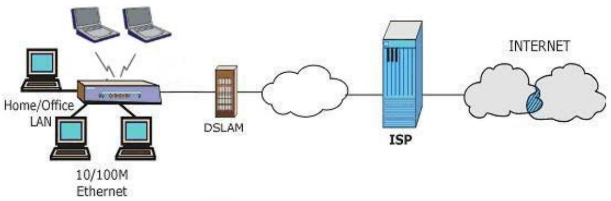
1.3.1 Internet Access
The Prestige is the ideal high-speed Internet access solution. Your Prestige supports the TCP/IP protocol, which the Internet uses exclusively. It is compatible with all major ADSL DSLAM (Digital Subscriber Line Access Multiplexer) providers. A DSLAM is a rack of ADSL line cards with data multiplexed into a backbone network interface/connection (for example, T1, OC3, DS3, ATM or Frame Relay). Think of it as the equivalent of a modem rack for ADSL. In addition, for the Prestige 652H/HW, you can insert an optional wireless PCMICA card into the Prestige and allow wireless clients access to your network resources. A typical Internet access application is shown below.
flowchart
graph LR
    A["Home/Office LAN"] --> B["10/100M Ethernet"]
    C["Laptop"] --> B
    D["Laptop"] --> B
    E["Laptop"] --> B
    B --> F["DSLAM"]
    F --> G["Cloud"]
    G --> H["ISP"]
    H --> I["Internet"]
Figure 1-1 Prestige Internet Access Application
Internet Single User Account
For a SOHO (Small Office/Home Office) environment, your Prestige offers the Single User Account (SUA) feature that allows multiple users on the LAN (Local Area Network) to access the Internet concurrently for the cost of a single IP address.
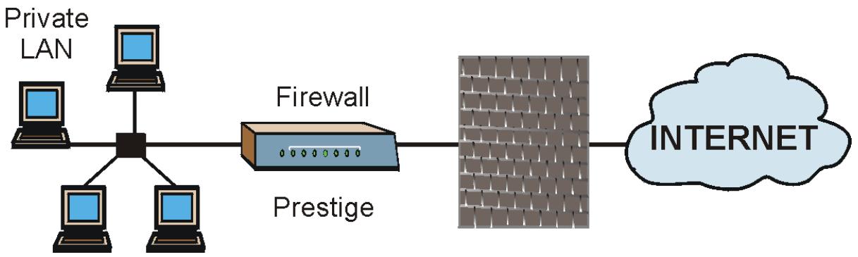
1.3.2 Firewall for Secure Broadband Internet Access
The Prestige provides protection from attacks by Internet hackers. By default, the firewall blocks all incoming traffic from the WAN. The firewall supports TCP/UDP inspection and DoS (Denial of Services) detection and prevention, as well as real time alerts, reports and logs.
flowchart
graph LR
    A["Private LAN"] --> B["Central Node"]
    B --> C["Firewall"]
    C --> D["Internet Cloud"]
    B --> E["Prestige"]
    E --> D
Figure 1-2 Firewall Application
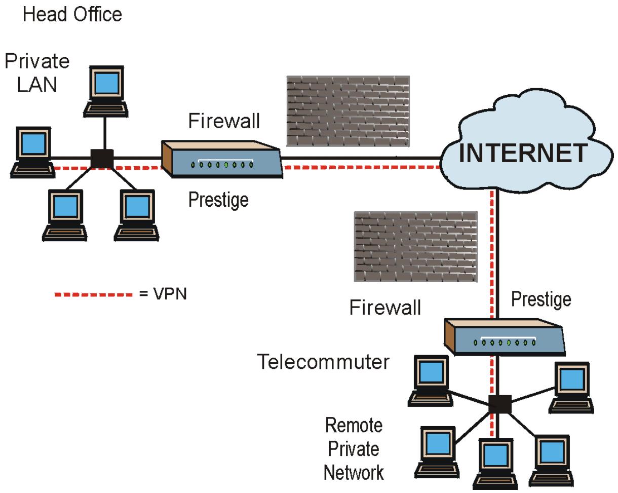
1.3.3 VPN Application
The Prestige's VPN feature makes it an ideal cost-effective way to connect branch offices and business partners over the Internet without the need (and expense) for leased lines between sites. VPN ensures the privacy and integrity of your data transmissions.
flowchart
graph TD
    A["Head Office"] --> B["Private LAN"]
    B --> C["Central Node"]
    C --> D["Firewall"]
    D --> E["Prestige"]
    E --> F["INTERNET"]
    F --> G["Prestige"]
    G --> H["Telecommuter"]
    H --> I["Remote Private Network"]
    style A fill:#f9f,stroke:#333
    style B fill:#ccf,stroke:#333
    style C fill:#cfc,stroke:#333
    style D fill:#fcc,stroke:#333
    style E fill:#cff,stroke:#333
    style F fill:#ffc,stroke:#333
    style G fill:#cfc,stroke:#333
    style H fill:#fcc,stroke:#333
    style I fill:#cfc,stroke:#333
Figure 1-3 VPN Application
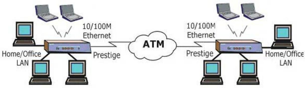
1.3.4 LAN to LAN Application
You can use the Prestige to connect two geographically dispersed networks over the ADSL line. A typical LAN-to-LAN application for your Prestige is shown as follows.
flowchart
graph LR
    A["Home/Office LAN"] --> B["3x 0.0670E"]
    B --> C["Prestige"]
    D["10/100M Ethernet"] --> E["ATM"]
    E --> F["2x 0.0670E"]
    F --> G["Prestige"]
    H["Home/Office LAN"] --> I["Home/Office LAN"]
    I --> J["10/100M Ethernet"]
    J --> K["Prestige"]
    L["10/100M Ethernet"] --> M["Home/Office LAN"]
    M --> N["10/100M Ethernet"]
    N --> O["Prestige"]
    P["Home/Office LAN"] --> Q["Home/Office LAN"]
    Q --> R["10/100M Ethernet"]
    R --> S["Prestige"]
    T["Home/Office LAN"] --> U["Home/Office LAN"]
    U --> V["10/100M Ethernet"]
    V --> W["Prestige"]
Figure 1-4 Prestige LAN-to-LAN Application
Chapter 2
Introducing the Web Configurator
This chapter describes how to access and navigate the web configurator.
2.1 Web Configurator Overview
The embedded web configurator allows you to manage the Prestige from anywhere through a browser such as Microsoft Internet Explorer or Netscape Navigator. Use Internet Explorer 6.0 and later or Netscape Navigator 7.0 and later versions with JavaScript enabled. It is recommended that you set your screen resolution to 1024 by 768 pixels
2.2 Accessing the Prestige Web Configurator
Step 1. Make sure your Prestige hardware is properly connected (refer to the Compact Guide or Read Me First).
Step 2. Prepare your computer/computer network to connect to the Prestige (refer to the Compact Guide or Read Me First).
Step 3. Launch your web browser.
Step 4. Type "192.168.1.1" as the URL.
Step 5. An Enter Network Password window displays. Enter the user name (“admin” is the default), password (“1234” is the default) and click OK.
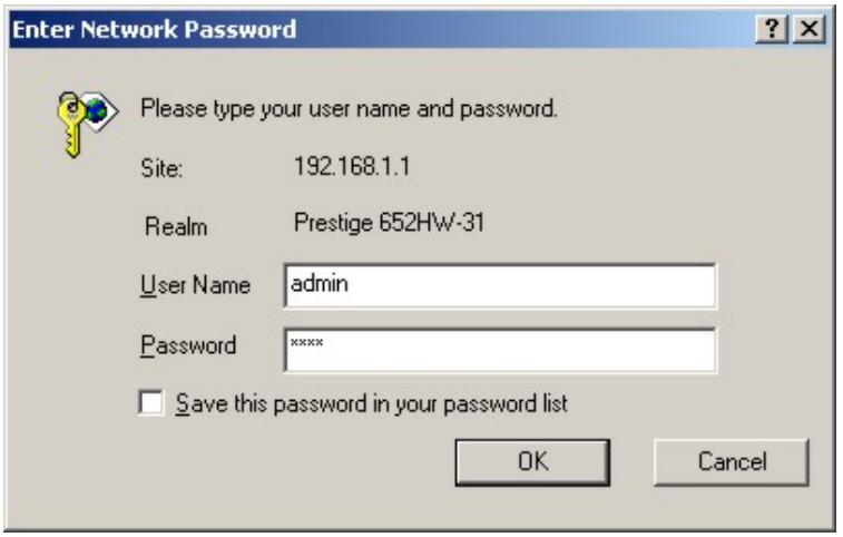
Figure 2-1 Password Screen
Step 6. You should now see the SITE MAP screen.
The Prestige automatically times out after five minutes of inactivity. Simply log back into the Prestige if this happens to you.
2.3 Navigating the Prestige Web Configurator
The following summarizes how to navigate the web configurator from the SITE MAP screen. Screens vary slightly for different Prestige models.
Select a language from the Language drop-down list box.
➢ Click Wizard Setup to begin a series of screens to configure your Prestige for the first time.
➢ Click a link under Advanced Setup to configure advanced Prestige features.
➢ Click a link under Maintenance to see Prestige performance statistics, upload firmware and back up, restore or upload a configuration file.
➢ Click Site Map to go to the Site Map screen.
➢ Click Logout in the navigation panel when you have finished a Prestige management session.
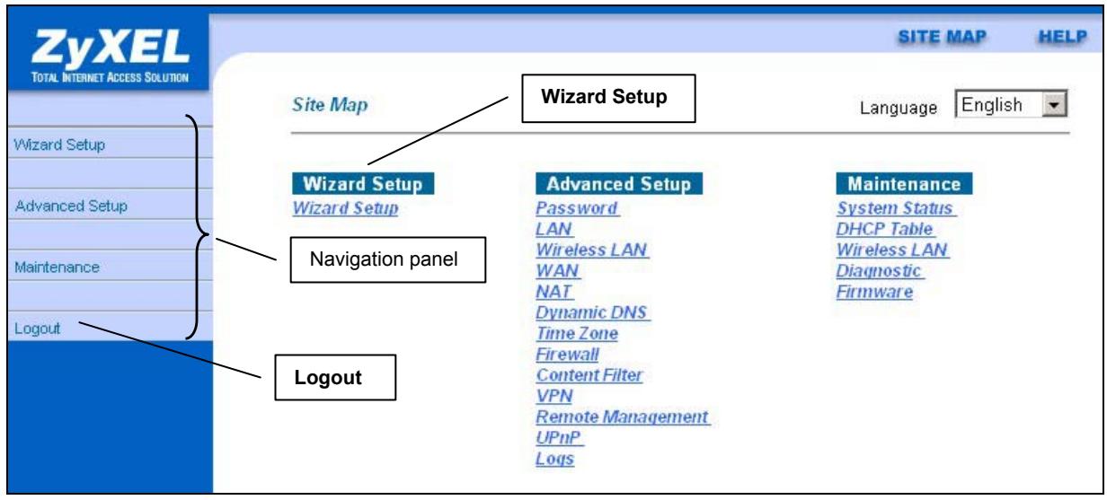
Figure 2-2 Web Configurator SITE MAP Screen
Click the HELP icon (located in the top right corner of most screens) to view embedded help.
2.4 Resetting the Prestige
If you forget your password or cannot access the SMT menu, you will need to reload the factory-default configuration file or use the RESET button the back of the Prestige. Uploading this configuration file replaces the current configuration file with the factory-default configuration file. This means that you will lose all configurations that you had previously and the speed of the console port will be reset to the default of 9600bps with 8 data bit, no parity, one stop bit and flow control set to none. The password will be reset to “1234”, also.
2.4.1 Using The Reset Button
Step 1. Make sure the SYS LED is on (not blinking).
Step 2. Press the RESET button for five seconds, and then release it. When the SYS LED begins to blink, the defaults have been restored and the Prestige restarts
2.4.2 Uploading a Configuration File Via Console Port
Download the default configuration file from the ZyXEL FTP site, unzip it and save it in a folder.
Step 1. Turn off the Prestige, begin a terminal emulation software session and turn on the Prestige again. When you see the message "Press Any key to enter Debug Mode within 3 seconds", press any key to enter debug mode.
Step 2. Enter "atlc" after "Enter Debug Mode" message.
Step 3. Wait for "Starting XMODEM upload" message before activating Xmodem upload on your terminal. This is an example Xmodem configuration upload using HyperTerminal.
Step 4. Click Transfer, then Send File to display the following screen.
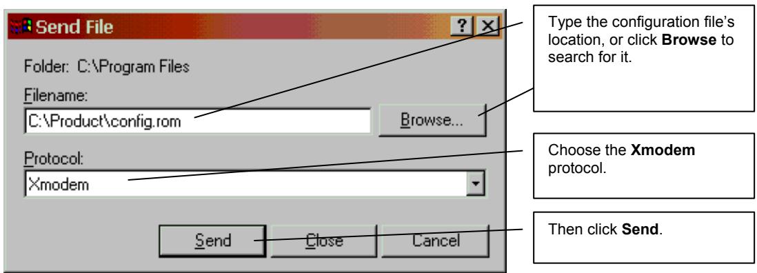
Figure 2-3 Example Xmodem Upload
Step 5. After successful firmware upload, enter "atgo" to restart the router.
Chapter 3
Wizard Setup
This chapter provides information on the Wizard Setup screens in the web configurator.
3.1 Wizard Setup Introduction
Use the Wizard Setup screens to configure your system for Internet access settings and fill in the fields with the information in the Internet Account Information table of the Compact Guide or Read Me First. Your ISP may have already configured some of the fields in the wizard screens for you.
3.2 Encapsulation
Be sure to use the encapsulation method required by your ISP. The Prestige supports the following methods.
3.2.1 ENET ENCAP
The MAC Encapsulated Routing Link Protocol (ENET ENCAP) is only implemented with the IP network protocol. IP packets are routed between the Ethernet interface and the WAN interface and then formatted so that they can be understood in a bridged environment. For instance, it encapsulates routed Ethernet frames into bridged ATM cells. ENET ENCAP requires that you specify a gateway IP address in the Ethernet Encapsulation Gateway field in the second wizard screen. You can get this information from your ISP.
3.2.2 PPP over Ethernet
PPPoE provides access control and billing functionality in a manner similar to dial-up services using PPP. The Prestige bridges a PPP session over Ethernet (PPP over Ethernet, RFC 2516) from your computer to an ATM PVC (Permanent Virtual Circuit) which connects to ADSL Access Concentrator where the PPP session terminates. One PVC can support any number of PPP sessions from your LAN. For more information on PPPoE, see the Appendices.
3.2.3 PPPoA
PPPoA stands for Point to Point Protocol over ATM Adaptation Layer 5 (AAL5). A PPPoA connection functions like a dial-up Internet connection. The Prestige encapsulates the PPP session based on RFC1483 and sends it through an ATM PVC (Permanent Virtual Circuit) to the Internet Service Provider's (ISP) DSLAM (digital access multiplexer). Please refer to RFC 2364 for more information on PPPoA. Refer to RFC 1661 for more information on PPP.
3.2.4 RFC 1483
RFC 1483 describes two methods for Multiprotocol Encapsulation over ATM Adaptation Layer 5 (AAL5). The first method allows multiplexing of multiple protocols over a single ATM virtual circuit (LLC-based multiplexing) and the second method assumes that each protocol is carried over a separate ATM virtual circuit (VC-based multiplexing). Please refer to the RFC for more detailed information.
3.3 Multiplexing
There are two conventions to identify what protocols the virtual circuit (VC) is carrying. Be sure to use the multiplexing method required by your ISP.
3.3.1 VC-based Multiplexing
In this case, by prior mutual agreement, each protocol is assigned to a specific virtual circuit; for example, VC1 carries IP, etc. VC-based multiplexing may be dominant in environments where dynamic creation of large numbers of ATM VCs is fast and economical.
3.3.2 LLC-based Multiplexing
In this case one VC carries multiple protocols with protocol identifying information being contained in each packet header. Despite the extra bandwidth and processing overhead, this method may be advantageous if it is not practical to have a separate VC for each carried protocol, for example, if charging heavily depends on the number of simultaneous VCs.
3.4 VPI and VCI
Be sure to use the correct Virtual Path Identifier (VPI) and Virtual Channel Identifier (VCI) numbers assigned to you. The valid range for the VPI is 0 to 255 and for the VCI is 32 to 65535 (0 to 31 is reserved for local management of ATM traffic). Please see the Appendices for more information.
3.5 Wizard Setup Configuration: First Screen
In the SITE MAP screen click Wizard Setup to display the first wizard screen.
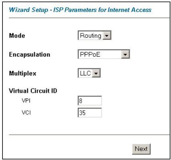
Figure 3-1 Wizard Screen 1
The following table describes the fields in this screen.
Table 3-1 Wizard Screen 1
| LABEL | DESCRIPTION |
| Mode | From the Mode drop-down list box, select Routing (default) if your ISP allows multiple computers to share an Internet account. Otherwise select Bridge. |
| Encapsulation | Select the encapsulation type your ISP uses from the Encapsulation drop-down list box.Choices vary depending on what you select in the Mode field.If you select Bridge in the Mode field, select either PPPoA or RFC 1483.If you select Routing in the Mode field, select PPPoA, RFC 1483, ENET ENCAP or PPPoE. |
| Multiplex | Select the multiplexing method used by your ISP from the Multiplex drop-down list box either VC-based or LLC-based. |
| Virtual Circuit ID | VPI (Virtual Path Identifier) and VCI (Virtual Channel Identifier) define a virtual circuit. Refer to the appendix for more information. |
| VPI | Enter the VPI assigned to you. This field may already be configured. |
| VCI | Enter the VCI assigned to you. This field may already be configured. |
Table 3-1 Wizard Screen 1
| LABEL | DESCRIPTION |
| Next | Click this button to go to the next wizard screen. The next wizard screen you see depends on what protocol you chose above. Click on the protocol link to see the next wizard screen for that protocol. |
3.6 IP Address and Subnet Mask
Similar to the way houses on a street share a common street name, so too do computers on a LAN share one common network number.
Where you obtain your network number depends on your particular situation. If the ISP or your network administrator assigns you a block of registered IP addresses, follow their instructions in selecting the IP addresses and the subnet mask.
If the ISP did not explicitly give you an IP network number, then most likely you have a single user account and the ISP will assign you a dynamic IP address when the connection is established. If this is the case, it is recommended that you select a network number from 192.168.0.0 to 192.168.255.0 and you must enable the Network Address Translation (NAT) feature of the Prestige. The Internet Assigned Number Authority (IANA) reserved this block of addresses specifically for private use; please do not use any other number unless you are told otherwise. Let's say you select 192.168.1.0 as the network number; which covers 254 individual addresses, from 192.168.1.1 to 192.168.1.254 (zero and 255 are reserved). In other words, the first three numbers specify the network number while the last number identifies an individual computer on that network.
Once you have decided on the network number, pick an IP address that is easy to remember, for instance, 192.168.1.1, for your Prestige, but make sure that no other device on your network is using that IP address.
The subnet mask specifies the network number portion of an IP address. Your Prestige will compute the subnet mask automatically based on the IP address that you entered. You don't need to change the subnet mask computed by the Prestige unless you are instructed to do otherwise.
3.7 IP Address Assignment
A static IP is a fixed IP that your ISP gives you. A dynamic IP is not fixed; the ISP assigns you a different one each time. The Single User Account feature can be enabled or disabled if you have either a dynamic or static IP. However the encapsulation method assigned influences your choices for IP address and ENET ENCAP Gateway.
3.7.1 IP Assignment with PPPoA or PPPoE Encapsulation
If you have a dynamic IP, then the IP Address and ENET ENCAP Gateway fields are not applicable (N/A). If you have a static IP, then you only need to fill in the IP Address field and not the ENET ENCAP Gateway field.
3.7.2 IP Assignment with RFC 1483 Encapsulation
In this case the IP Address Assignment must be static with the same requirements for the IP Address and ENET ENCAP Gateway fields as stated above.
3.7.3 IP Assignment with ENET ENCAP Encapsulation
In this case you can have either a static or dynamic IP. For a static IP you must fill in all the IP Address and ENET ENCAP Gateway fields as supplied by your ISP. However for a dynamic IP, the Prestige acts as a DHCP client on the WAN port and so the IP Address and ENET ENCAP Gateway fields are not applicable (N/A) as the DHCP server assigns them to the Prestige.
3.7.4 Private IP Addresses
Every machine on the Internet must have a unique address. If your networks are isolated from the Internet, for example, only between your two branch offices, you can assign any IP addresses to the hosts without problems. However, the Internet Assigned Numbers Authority (IANA) has reserved the following three blocks of IP addresses specifically for private networks:
| 10.0.0.0 | - | 10.255.255.255 |
| 172.16.0.0 | - | 172.31.255.255 |
| 192.168.0.0 | - | 192.168.255.255 |
You can obtain your IP address from the IANA, from an ISP or it can be assigned from a private network. If you belong to a small organization and your Internet access is through an ISP, the ISP can provide you with the Internet addresses for your local networks. On the other hand, if you are part of a much larger organization, you should consult your network administrator for the appropriate IP addresses.
Regardless of your particular situation, do not create an arbitrary IP address; always follow the guidelines above. For more information on address assignment, please refer to RFC 1597, Address Allocation for Private Internets and RFC 1466, Guidelines for Management of IP Address Space.
3.8 Nailed-Up Connection (PPP)
A nailed-up connection is a dial-up line where the connection is always up regardless of traffic demand. The Prestige does two things when you specify a nailed-up connection. The first is that idle timeout is disabled. The second is that the Prestige will try to bring up the connection when turned on and whenever the connection is down. A nailed-up connection can be very expensive for obvious reasons.
Do not specify a nailed-up connection unless your telephone company offers flat-rate service or you need a constant connection and the cost is of no concern
3.9 NAT
NAT (Network Address Translation - NAT, RFC 1631) is the translation of the IP address of a host in a packet, for example, the source address of an outgoing packet, used within one network to a different IP address known within another network.
3.10 Wizard Setup Configuration: Second Screen
The second wizard screen varies depending on what mode and encapsulation type you use. All screens shown are with routing mode. Configure the fields and click Next to continue.
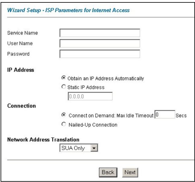
Figure 3-2 Internet Connection with PPPoE
The following table describes the fields in this screen.
Table 3-2 Internet Connection with PPPoE
| LABEL | DESCRIPTION |
| Service Name | Type the name of your PPPoE service here. |
| User Name | Enter the user name exactly as your ISP assigned. If assigned a name in the formuser@domainwhere domain identifies a service name, then enter both components exactly as given. |
| Password | Enter the password associated with the user name above. |
| IP Address | A static IP address is a fixed IP that your ISP gives you. A dynamic IP address is not fixed; the ISP assigns you a different one each time you connect to the Internet. The Single User Account feature can be used with either a dynamic or static IP address.SelectObtain an IP Address Automaticallyif you have a dynamic IP address; otherwise selectStatic IP Addressand type your ISP assigned IP address in theIP Addresstext box below. |
| Connection | SelectConnect on Demandwhen you don't want the connection up all the time and specify an idle time-out (in seconds) in theMax. Idle Timeoutfield. The default setting selectsConnection on Demandwith 0 as the idle time-out, which means the Internet session will not timeout.SelectNailed-Up Connectionwhen you want your connection up all the time. The Prestige will try to bring up the connection automatically if it is disconnected.The schedule rule(s) in SMT menu 26 has priority over yourConnectionsettings. |
| Network Address Translation | Select None, SUA Onlyor Full Featurefrom the drop-sown list box. Refer to the NAT chapter for more details. |
| Back | ClickBackto go back to the first wizard screen. |
| Next | ClickNextto continue to the next wizard screen. |
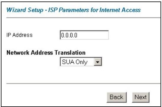
Figure 3-3 Internet Connection with RFC 1483
The following table describes the fields in this screen.
Table 3-3 Internet Connection with RFC 1483
| LABEL | DESCRIPTION |
| IP Address | This field is available if you selectRoutingin theModefield.Type your ISP assigned IP address in this field. |
| Network Address Translation | Select None, SUA Onlyor Full Featurefrom the drop-sown list box. Refer to the NAT chapter for more details. |
| Back | ClickBackto go back to the first wizard screen. |
| Next | ClickNextto continue to the next wizard screen. |
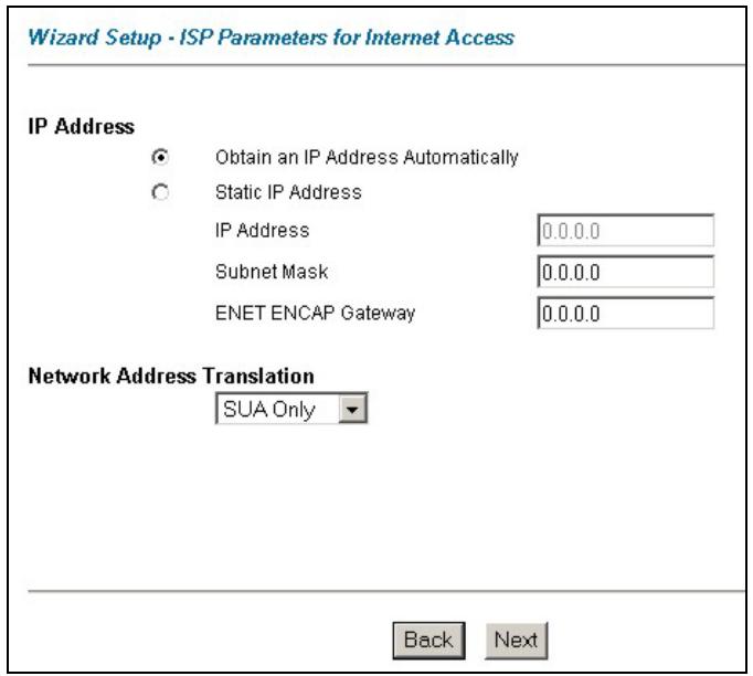
Figure 3-4 Internet Connection with ENET ENCAP
The following table describes the fields in this screen.
Table 3-4 Internet Connection with ENET ENCAP
| LABEL | DESCRIPTION |
| IP Address | A static IP address is a fixed IP that your ISP gives you. A dynamic IP address is not fixed; the ISP assigns you a different one each time you connect to the Internet. The Single User Account feature can be used with either a dynamic or static IP address.Select Obtain an IP Address Automatically if you have a dynamic IP address; otherwise select Static IP Address and type your ISP assigned IP address in the IP Address text box below. |
| Subnet Mask | Enter a subnet mask in dotted decimal notation.Refer to the IP Subnetting appendix to calculate a subnet mask If you are implementing subnetting. |
| ENET ENCAP Gateway | You must specify a gateway IP address (supplied by your ISP) when you use ENET ENCAP in the Encapsulation field in the previous screen. |
Table 3-4 Internet Connection with ENET ENCAP
| LABEL | DESCRIPTION |
| Network Address Translation | Select None, SUA Only or Full Feature from the drop-sown list box. Refer to the NAT chapter for more details. |
| Back | Click Back to go back to the first wizard screen. |
| Next | Click Next to continue to the next wizard screen. |
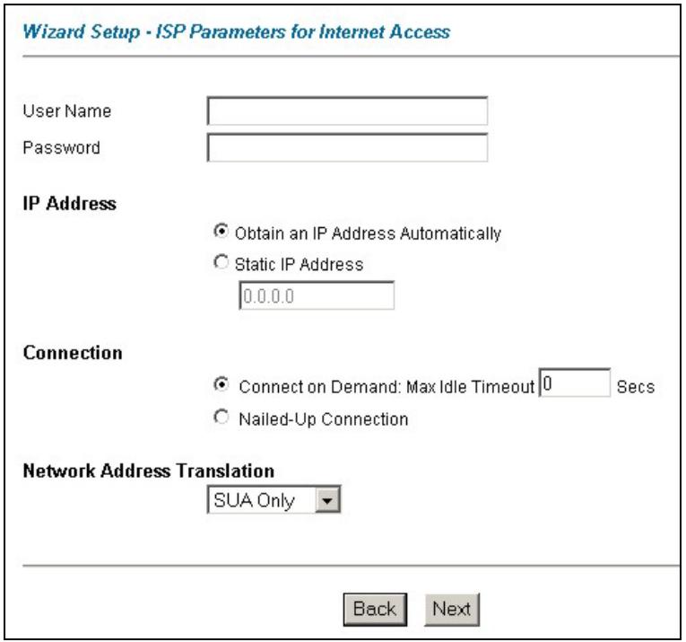
Figure 3-5 Internet Connection with PPPoA
The following table describes the fields in this screen.
Table 3-5 Internet Connection with PPPoA
| LABEL | DESCRIPTION |
| User Name | Enter the login name that your ISP gives you. |
| Password | Enter the password associated with the user name above. |
| IP Address | This option is available if you selectRoutingin theModefield.A static IP address is a fixed IP that your ISP gives you. A dynamic IP address is not fixed; the ISP assigns you a different one each time you connect to the Internet. The Single User Account feature can be used with either a dynamic or static IP address.ClickObtain an IP Address Automaticallyif you have a dynamic IP address; otherwise clickStatic IP Addressand type your ISP assigned IP address in theIP Addresstext box below. |
| Connection | SelectConnect on Demandwhen you don't want the connection up all the time and specify an idle time-out (in seconds) in theMax. Idle Timeoutfield. The default setting selectsConnection on Demandwith 0 as the idle time-out, which means the Internet session will not timeout.SelectNailed-Up Connectionwhen you want your connection up all the time. The Prestige will try to bring up the connection automatically if it is disconnected.The schedule rule(s) in SMT menu 26 has priority over yourConnectionsettings. |
| Network Address Translation | This option is available if you selectRoutingin theModefield.Select None, SUA Onlyor Full Featurefrom the drop-sown list box. Refer to the NAT chapter for more details. |
| Back | ClickBackto go back to the first wizard screen. |
| Next | ClickNextto continue to the next wizard screen. |
3.11 DHCP Setup
DHCP (Dynamic Host Configuration Protocol, RFC 2131 and RFC 2132) allows individual clients to obtain TCP/IP configuration at start-up from a server. You can configure the Prestige as a DHCP server or disable it. When configured as a server, the Prestige provides the TCP/IP configuration for the clients. If you turn DHCP service off, you must have another DHCP server on your LAN, or else the computer must be manually configured.
3.11.1 IP Pool Setup
The Prestige is pre-configured with a pool of 32 IP addresses starting from 192.168.1.33 to 192.168.1.64 for the client machines. This leaves 31 IP addresses, 192.168.1.2 to 192.168.1.32 (excluding the Prestige itself which has a default IP of 192.168.1.1) for other server machines, for example, server for mail, FTP, telnet, web, etc., that you may have.
3.12 Wizard Setup Configuration: Third Screen
Step 1. Verify the settings in the screen shown next. To change the LAN information on the Prestige, click Change LAN Configurations. Otherwise click Save Settings to save the configuration and skip to the section 3.13.
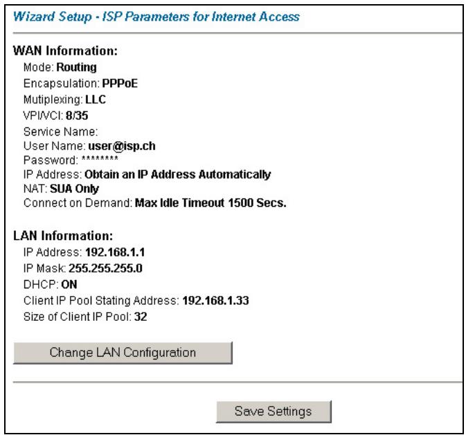
Figure 3-6 Wizard Screen 3
Step 2. If you want to change your Prestige LAN settings, click Change LAN Configuration to display the screen as shown next.
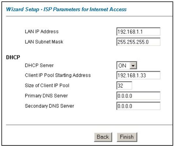
Figure 3-7 Wizard : LAN Configuration
The following table describes the fields in this screen.
Table 3-6 Wizard : LAN Configuration
| LABEL | DESCRIPTION |
| LAN IP Address | Enter the IP address of your Prestige in dotted decimal notation, for example, 192.168.1.1 (factory default).If you changed the Prestige's LAN IP address, you must use the new IP address if you want to access the web configurator again. |
| LAN Subnet Mask | Enter a subnet mask in dotted decimal notation. |
| DHCP | |
| DHCP Server | From the DHCP Server drop-down list box, select On to allow your Prestige to assign IP addresses, an IP default gateway and DNS servers to computer systems that support the DHCP client. Select Off to disable DHCP server.When DHCP server is used, set the following items: |
Table 3-6 Wizard : LAN Configuration
| LABEL | DESCRIPTION |
| Client IP Pool Starting Address | This field specifies the first of the contiguous addresses in the IP address pool. |
| Size of Client IP Pool | This field specifies the size or count of the IP address pool. |
| Primary DNS Server | Enter the IP addresses of the DNS servers. The DNS servers are passed to the DHCP clients along with the IP address and the subnet mask. |
| Secondary DNS Server | As above. |
| Back | Click Back to go back to the previous screen. |
| Finish | Click Finish to save the settings and proceed to the next wizard screen. |
3.13 Wizard Setup Configuration: Connection Tests
The Prestige automatically tests the connection to the computer(s) connected to the LAN ports. To test the connection from the Prestige to the ISP, click Start Diagnose. Otherwise click Return to Main Menu to go back to the Site Map screen.
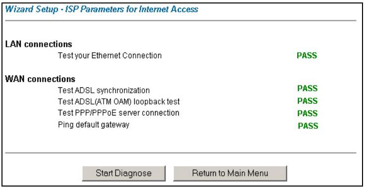
Figure 3-8 Wizard Screen 4
3.14 Test Your Internet Connection
Launch your web browser and navigate to www.zyxel.com. Internet access is just the beginning. Refer to the rest of this User's Guide for more detailed information on the complete range of Prestige features. If you cannot access the Internet, open the web configurator again to confirm that the Internet settings you configured in the Wizard Setup are correct.
Part II:
Password, LAN, Wireless LAN and WAN
This part covers the password, LAN (Local Area Network), wireless LAN and WAN setup.
Chapter 4
Password Setup
This chapter provides information on the Password screen.
4.1 Password Overview
It is highly recommended that you change the password for accessing the Prestige.
4.2 Configuring Password
To change your Prestige's password (recommended), click Password. The screen appears as shown.
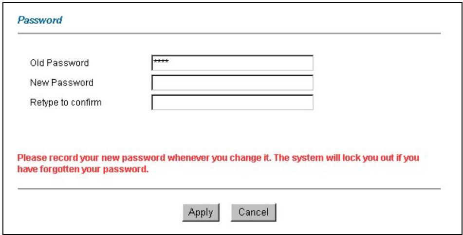
Figure 4-1 Password
The following table describes the fields in this screen.
Table 4-1 Password
| LABEL | DESCRIPTION |
| Old Password | Type the default password or the existing password you use to access the system in this field. |
| New Password | Type the new password in this field. |
Table 4-1 Password
| LABEL | DESCRIPTION |
| Retype to Confirm | Type the new password again in this field. |
| Apply | Click Apply to save your changes back to the Prestige. |
| Cancel | Click Cancel to begin configuring this screen afresh. |
Chapter 5
LAN Setup
This chapter describes how to configure LAN settings.
5.1 LAN Overview
A Local Area Network (LAN) is a shared communication system to which many computers are attached. A LAN is a computer network limited to the immediate area, usually the same building or floor of a building. The LAN screens can help you configure a LAN DHCP server and manage IP addresses.
5.1.1 LANs, WANs and the Prestige
The actual physical connection determines whether the Prestige ports are LAN or WAN ports. There are two separate IP networks, one inside, the LAN network; the other outside: the WAN network as shown next:
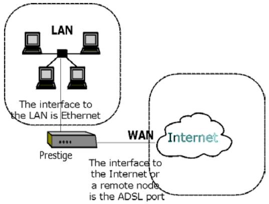
flowchart
graph TD
    A["LAN"] --> B["The interface to the LAN is Ethernet"]
    B --> C["Prestige"]
    C --> D["Internet"]
    D --> E["WAN"]
    style A fill:#f9f,stroke:#333
    style B fill:#ccf,stroke:#333
    style C fill:#cfc,stroke:#333
    style D fill:#fcc,stroke:#333
    style E fill:#cff,stroke:#333
Figure 5-1 LAN and WAN IP Addresses
5.2 DNS Server Address
DNS (Domain Name System) is for mapping a domain name to its corresponding IP address and vice versa, for example, the IP address of www.zyxel.com is 204.217.0.2. The DNS server is extremely important because without it, you must know the IP address of a machine before you can access it. The DNS server addresses that you enter in the DHCP setup are passed to the client machines along with the assigned IP address and subnet mask.
There are two ways that an ISP disseminates the DNS server addresses. The first is for an ISP to tell a customer the DNS server addresses, usually in the form of an information sheet, when s/he signs up. If your
ISP gives you the DNS server addresses, enter them in the DNS Server fields in DHCP Setup, otherwise, leave them blank.
Some ISP's choose to pass the DNS servers using the DNS server extensions of PPP IPCP (IP Control Protocol) after the connection is up. If your ISP did not give you explicit DNS servers, chances are the DNS servers are conveyed through IPCP negotiation. The Prestige supports the IPCP DNS server extensions through the DNS proxy feature.
If the Primary and Secondary DNS Server fields in DHCP Setup are not specified, for instance, left as 0.0.0.0, the Prestige tells the DHCP clients that it itself is the DNS server. When a computer sends a DNS query to the Prestige, the Prestige forwards the query to the real DNS server learned through IPCP and relays the response back to the computer.
Please note that DNS proxy works only when the ISP uses the IPCP DNS server extensions. It does not mean you can leave the DNS servers out of the DHCP setup under all circumstances. If your ISP gives you explicit DNS servers, make sure that you enter their IP addresses in the DHCP Setup menu. This way, the Prestige can pass the DNS servers to the computers and the computers can query the DNS server directly without the Prestige's intervention.
5.3 DNS Server Address Assignment
Use DNS (Domain Name System) to map a domain name to its corresponding IP address and vice versa. The DNS server is extremely important because without it, you must know the IP address of a computer before you can access it.
There are two ways that an ISP disseminates the DNS server addresses.
- The ISP tells you the DNS server addresses, usually in the form of an information sheet, when you sign up. If your ISP gives you DNS server addresses, enter them in the DNS Server fields in DHCP Setup.
- Leave the DNS Server fields in DHCP Setup blank (for example 0.0.0.0). The Prestige acts as a DNS proxy when this field is blank.
5.4 LAN TCP/IP
The Prestige has built-in DHCP server capability that assigns IP addresses and DNS servers to systems that support DHCP client capability.
5.4.1 Factory LAN Defaults
The LAN parameters of the Prestige are preset in the factory with the following values:
IP address of 192.168.1.1 with subnet mask of 255.255.255.0 (24 bits)
DHCP server enabled with 32 client IP addresses starting from 192.168.1.33.
These parameters should work for the majority of installations. If your ISP gives you explicit DNS server address(es), read the embedded web configurator help regarding what fields need to be configured.
5.4.2 IP Address and Subnet Mask
Refer to the IP Address and Subnet Mask section in the Wizard Setup chapter for this information.
5.4.3 RIP Setup
RIP (Routing Information Protocol) allows a router to exchange routing information with other routers. The RIP Direction field controls the sending and receiving of RIP packets. When set to:
- Both - the Prestige will broadcast its routing table periodically and incorporate the RIP information that it receives.
- In Only - the Prestige will not send any RIP packets but will accept all RIP packets received.
- Out Only - the Prestige will send out RIP packets but will not accept any RIP packets received.
- None - the Prestige will not send any RIP packets and will ignore any RIP packets received.
The Version field controls the format and the broadcasting method of the RIP packets that the Prestige sends (it recognizes both formats when receiving). RIP-1 is universally supported; but RIP-2 carries more information. RIP-1 is probably adequate for most networks, unless you have an unusual network topology.
Both RIP-2B and RIP-2M sends the routing data in RIP-2 format; the difference being that RIP-2B uses subnet broadcasting while RIP-2M uses multicasting.
5.4.4 Multicast
Traditionally, IP packets are transmitted in one of either two ways - Unicast (1 sender - 1 recipient) or Broadcast (1 sender - everybody on the network). Multicast delivers IP packets to a group of hosts on the network - not everybody and not just 1.
IGMP (Internet Group Multicast Protocol) is a network-layer protocol used to establish membership in a Multicast group - it is not used to carry user data. IGMP version 2 (RFC 2236) is an improvement over version 1 (RFC 1112) but IGMP version 1 is still in wide use. If you would like to read more detailed information about interoperability between IGMP version 2 and version 1, please see sections 4 and 5 of RFC 2236. The class D IP address is used to identify host groups and can be in the range 224.0.0.0 to 239.255.255.255. The address 224.0.0.0 is not assigned to any group and is used by IP multicast computers. The address 224.0.0.1 is used for query messages and is assigned to the permanent group of all IP hosts (including gateways). All hosts must join the 224.0.0.1 group in order to participate in IGMP. The address 224.0.0.2 is assigned to the multicast routers group.
The Prestige supports both IGMP version 1 (IGMP-v1) and IGMP version 2 (IGMP-v2). At start up, the Prestige queries all directly connected networks to gather group membership. After that, the Prestige periodically updates this information. IP multicasting can be enabled/disabled on the Prestige LAN and/or WAN interfaces in the web configurator (LAN; WAN). Select None to disable IP multicasting on these interfaces.
5.5 Configuring LAN
Click LAN to open the following screen.
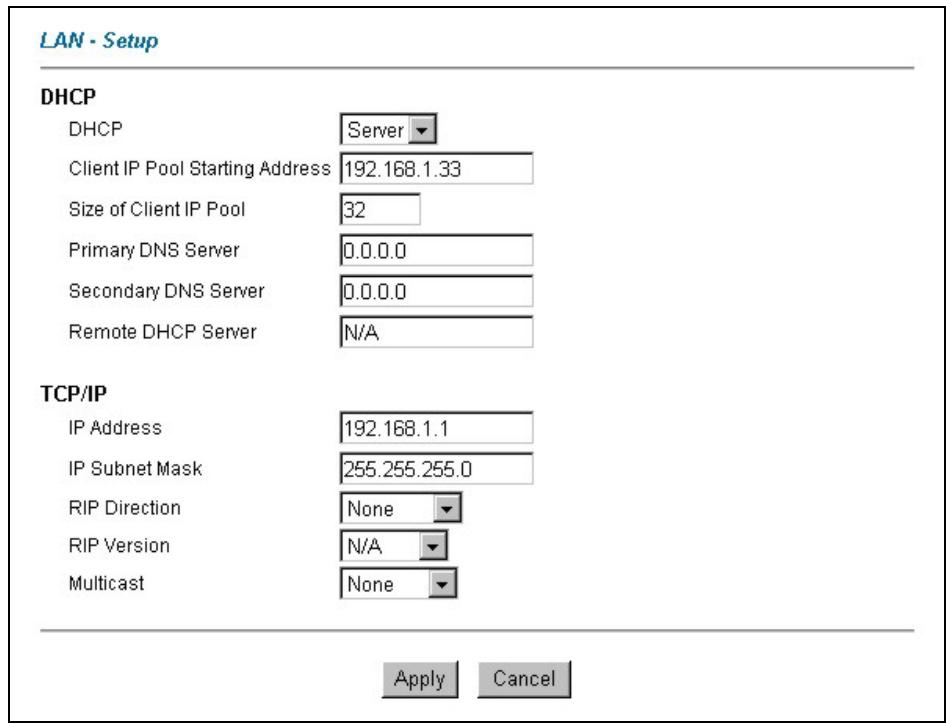
Figure 5-2 LAN
The following table describes the fields in this screen.
Table 5-1 LAN
| LABEL | DESCRIPTION |
| DHCP | |
Table 5-1 LAN
| LABEL | DESCRIPTION |
| DHCP | If set to Server, your Prestige can assign IP addresses, an IP default gateway and DNS servers to Windows 95, Windows NT and other systems that support the DHCP client.If set to None, the DHCP server will be disabled.If set to Relay, the Prestige acts as a surrogate DHCP server and relays DHCP requests and responses between the remote server and the clients. Enter the IP address of the actual, remote DHCP server in the Remote DHCP Server field in this case.When DHCP is used, the following items need to be set: |
| Client IP Pool Starting Address | This field specifies the first of the contiguous addresses in the IP address pool. |
| Size of Client IP Pool | This field specifies the size or count of the IP address pool. |
| Primary DNS Server | Enter the IP addresses of the DNS servers. The DNS servers are passed to the DHCP clients along with the IP address and the subnet mask. |
| Secondary DNS Server | As above. |
| Remote DHCP Server | If Relay is selected in the DHCP field above then enter the IP address of the actual remote DHCP server here. |
| TCP/IP | |
| IP Address | Enter the IP address of your Prestige in dotted decimal notation, for example, 192.168.1.1 (factory default). |
| IP Subnet Mask | Type the subnet mask assigned to you by your ISP (if given). |
| RIP Direction | Select the RIP direction from None, Both, In Only and Out Only. |
| RIP Version | Select the RIP version from RIP-1, RIP-2B and RIP-2M. |
| Multicast | IGMP (Internet Group Multicast Protocol) is a session-layer protocol used to establish membership in a multicast group. The Prestige supports both IGMP version 1 (IGMP-v1) and IGMP-v2. Select None to disable it. |
| Apply | Click this button to save these settings back to the Prestige. |
Table 5-1 LAN
| LABEL | DESCRIPTION |
| Cancel | Click this button to reset the fields in this screen. |
Chapter 6
Wireless LAN Setup
This chapter discusses how to configure Wireless LAN on the Prestige. This chapter only applies to the Prestige 652H/HW.
6.1 Wireless LAN Overview
This section introduces the wireless LAN and some basic configurations. Wireless LANs can be as simple as two computers with wireless LAN cards communicating in a peer-to-peer network or as complex as a number of computers with wireless LAN cards communicating through access points which bridge network traffic to the wired LAN.
The WLAN screens are only available when a WLAN card is installed.
6.1.1 Additional Installation Requirements for Using 802.1x
A computer with an IEEE 802.11b wireless LAN card and equipped with a web browser (with JavaScript enabled) and/or Telnet.
A wireless station computer must be running IEEE 802.1x-compliant software. Currently, this is offered in Windows XP.
➢ An optional network RADIUS server for remote user authentication and accounting.
6.1.2 Channel
The range of radio frequencies used by IEEE 802.11b wireless devices is called a “channel”. Channels available depend on your geographical area. You may have a choice of channels (for your region) so you should use a different channel than an adjacent AP (access point) to reduce interference. Interference occurs when radio signals from different access points overlap causing interference and degrading performance.
Adjacent channels partially overlap however. To avoid interference due to overlap, your AP should be on a channel at least five channels away from a channel that an adjacent AP is using. For example, if your region has 11 channels and an adjacent AP is using channel 1, then you need to select a channel between 6 or 11.
6.1.3 ESS ID
An Extended Service Set (ESS) is a group of access points or wireless gateways connected to a wired LAN on the same subnet. An ESS ID uniquely identifies each set. All access points or wireless gateways and their associated wireless stations in the same set must have the same ESSID.
6.1.4 RTS/CTS
A hidden node occurs when two stations are within range of the same access point, but are not within range of each other. The following figure illustrates a hidden node. Both stations (STA) are within range of the access point (AP) or wireless gateway, but out-of-range of each other, so they cannot “hear” each other, that is they do not know if the channel is currently being used. Therefore, they are considered hidden from each other.
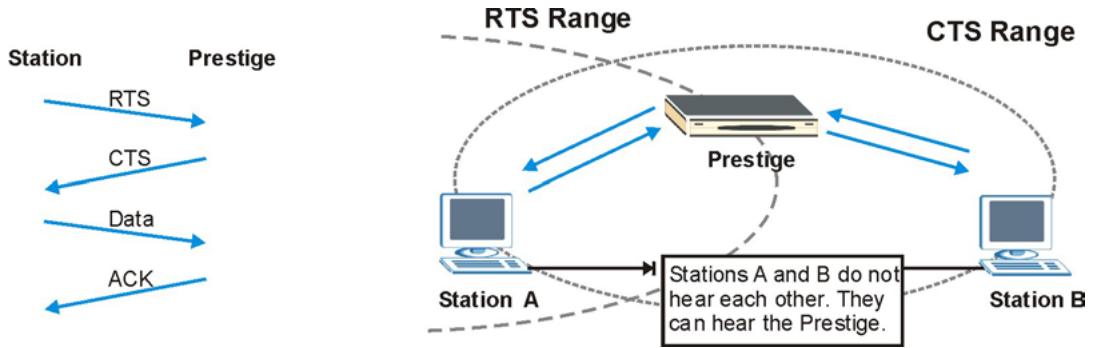
flowchart
graph TD
    subgraph_Stations_A["Station A"]
        RTS1["RTS"] --> Prestige1["Prestige"]
        CTS1["CTS"] --> Prestige1
        Data1["Data"] --> Prestige1
        ACK1["ACK"] --> Prestige1
    end
    subgraph_Stations_B["Station B"]
        Prestige2["Prestige"] --> CTS2["CTS Range"]
        CTS2 --> Prestige2
        Prestige2 --> Station3["Station A"]
        Prestige2 --> Station4["Station B"]
        Prestige2 --> CTS3["CTS Range"]
        CTS3 --> Prestige3["Prestige"]
        CTS3 --> CTS4["CTS Range"]
        CTS4 --> Station5["Station A and B"]
        CTS4 --> Station6["Station B"]
    end
    Note: Stations A and B do not hear each other. They can hear the Prestige.
Figure 6-1 RTS/CTS
When station A sends data to the Prestige, it might not know that the station B is already using the channel. If these two stations send data at the same time, collisions may occur when both sets of data arrive at the AP at the same time, resulting in a loss of messages for both stations.
RTS/CTS is designed to prevent collisions due to hidden nodes. An RTS/CTS defines the biggest size data frame you can send before an RTS (Request To Send)/CTS (Clear to Send) handshake is invoked.
When a data frame exceeds the RTS/CTS value you set (between 0 to 2432 bytes), the station that wants to transmit this frame must first send an RTS (Request To Send) message to the AP for permission to send it. The AP then responds with a CTS (Clear to Send) message to all other stations within its range to notify them to defer their transmission. It also reserves and confirms with the requesting station the time frame for the requested transmission.
Stations can send frames smaller than the specified RTS/CTS directly to the AP without the RTS (Request To Send)/CTS (Clear to Send) handshake.
You should only configure RTS/CTS if the possibility of hidden nodes exists on your network and the “cost” of resending large frames is more than the extra network overhead involved in the RTS (Request To Send)/CTS (Clear to Send) handshake.
If the RTS/CTS value is greater than the Fragmentation Threshold value (see next), then the RTS (Request To Send)/CTS (Clear to Send) handshake will never occur as data frames will be fragmented before they reach RTS/CTS size.
Enabling the RTS Threshold causes redundant network overhead that could negatively affect the throughput performance instead of providing a remedy.
6.1.5 Fragmentation Threshold
A Fragmentation Threshold is the maximum data fragment size (between 256 and 2432 bytes) that can be sent in the wireless network before the Prestige will fragment the packet into smaller data frames.
A large Fragmentation Threshold is recommended for networks not prone to interference while you should set a smaller threshold for busy networks or networks that are prone to interference.
If the Fragmentation Threshold value is smaller than the RTS/CTS value (see previously) you set then the RTS (Request To Send)/CTS (Clear to Send) handshake will never occur as data frames will be fragmented before they reach RTS/CTS size.
6.2 Levels of Security
Wireless security is vital to your network to protect wireless communication between wireless stations, access points and the wired network.
The figure below shows the possible wireless security levels on your Prestige. The highest security level relies on EAP (Extensible Authentication Protocol) for authentication and utilizes dynamic WEP key exchange. It requires interaction with a RADIUS (Remote Authentication Dial-In User Service) server either on the WAN or your LAN to provide authentication service for wireless stations.
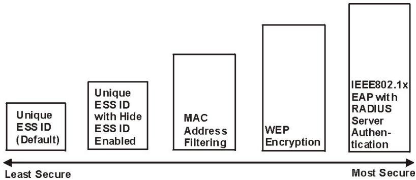
flowchart
graph LR
    A["Unique ESS ID (Default)"] --> B["Unique ESS ID with Hide ESS ID Enabled"]
    B --> C["MAC Address Filtering"]
    C --> D["WEP Encryption"]
    D --> E["IEEE802.1x EAP with RADIUS Server Authentication"]
    style A fill:#f9f,stroke:#333
    style B fill:#f9f,stroke:#333
    style C fill:#f9f,stroke:#333
    style D fill:#f9f,stroke:#333
    style E fill:#f9f,stroke:#333
Figure 6-2 Prestige Wireless Security Levels
If you do not enable any wireless security on your Prestige, your network is accessible to any wireless networking device that is within range.
Use the Prestige web configurator to configurator to set up your wireless LAN security settings. Refer to the chapter on using the Prestige web configurator to see how to access the web configurator.
6.3 Data Encryption with WEP
WEP encryption scrambles the data transmitted between the wireless stations and the access points to keep network communications private. It encrypts unicast and multicast communications in a network. Both the wireless stations and the access points must use the same WEP key for data encryption and decryption.
Your Prestige allows you to configure up to four 64-bit or 128-bit WEP keys but only one key can be enabled at any one time.
In order to configure and enable WEP encryption; click Wireless LAN and Wireless to the display the Wireless screen.
6.4 Inserting a PCMCIA Wireless LAN Card
Use a ZyAIR series wireless LAN PCMCIA card to add optional wireless LAN capabilities.
Step 1. Turn off the Prestige.
Never insert or remove a wireless LAN card when the Prestige is turned on.
Step 2. Locate the slot labeled Wireless LAN on the Prestige.
Step 3. With its pin connector facing the slot and the LED side facing upwards, slide the ZyAIR wireless LAN card into the slot.
Never force, bend or twist the wireless LAN card into the slot.
Step 4. Turn on the Prestige. The WLAN LED should turn on.
6.5 Configuring Wireless LAN
If you are configuring the Prestige from a computer connected to the wireless LAN and you change the Prestige's ESSID or WEP settings, you will lose your wireless connection when you press Apply to confirm. You must then change the wireless settings of your computer to match the Prestige's new settings.
Click Wireless LAN, Wireless to open the Wireless screen.
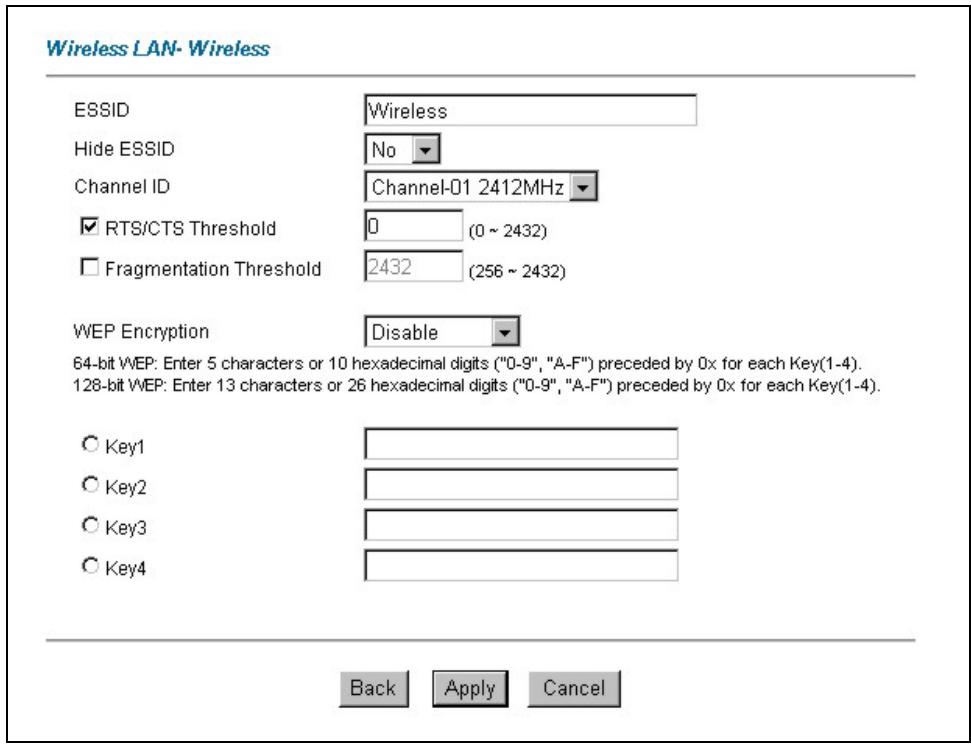
Figure 6-3 Wireless
The following table describes the fields in this screen.
Table 6-1 Wireless
| LABEL | DESCRIPTION |
| ESSID | The ESSID (Extended Service Set Identification) is a unique name to identify the Prestige in the wireless LAN. Wireless stations associating to the Prestige must have the same ESSID. Enter a descriptive name (up to 32 characters). |
| Hide ESSID | Select Yes to hide the ESSID in so a station cannot obtain the ESSID through passive scanning.Select No to make the ESSID visible so a station can obtain the ESSID through passive scanning. |
| Channel ID | The range of radio frequencies used by IEEE 802.11b wireless devices is called a channel. Select a channel from the drop-down list box. |
Table 6-1 Wireless
| LABEL | DESCRIPTION |
| RTS/CTS Threshold | The RTS (Request To Send) threshold (number of bytes) for enabling RTS/CTS handshake. Data with its frame size larger than this value will perform the RTS/CTS handshake. Setting this attribute to be larger than the maximum MSDU (MAC service data unit) size turns off the RTS/CTS handshake. Setting this attribute to zero turns on the RTS/CTS handshake.Enter a value between 0 and 2432. |
| Fragmentation Threshold | The threshold (number of bytes) for the fragmentation boundary for directed messages. It is the maximum data fragment size that can be sent.Enter a value between 256 and 2432. |
| WEP Encryption | WEP (Wired Equivalent Privacy) encrypts data frames before transmitting over the wireless network.Select Disable to allow all wireless computers to communicate with the access points without any data encryption.Select 64-bit WEP or 128-bit WEP to use data encryption. |
| Key 1 to Key 4 | The WEP keys are used to encrypt data. Both the Prestige and the wireless stations must use the same WEP key for data transmission.If you chose 64-bit WEP, then enter any 5 ASCII characters or 10 hexadecimal characters ("0-9", "A-F").If you chose 128-bit WEP, then enter 13 ASCII characters or 26 hexadecimal characters ("0-9", "A-F").You must configure all four keys, but only one key can be activated at any one time. The default key is key 1. |
| Back | Click Back to go to the main wireless LAN setup screen. |
| Apply | Click Apply to save your changes back to the Prestige. |
| Cancel | Click Cancel to begin configuring this screen afresh. |
6.6 Configuring MAC Filter
The MAC filter screen allows you to configure the Prestige to give exclusive access to up to 32 devices (Allow Association) or exclude up to 32 devices from accessing the Prestige (Deny Association). Every Ethernet device has a unique MAC (Media Access Control) address. The MAC address is assigned at the factory and consists of six pairs of hexadecimal characters, for example, 00:A0:C5:00:00:02. You need to know the MAC address of the devices to configure this screen.
To change your Prestige's MAC filter settings, click Wireless LAN, MAC Filter to open the MAC Filter screen. The screen appears as shown.
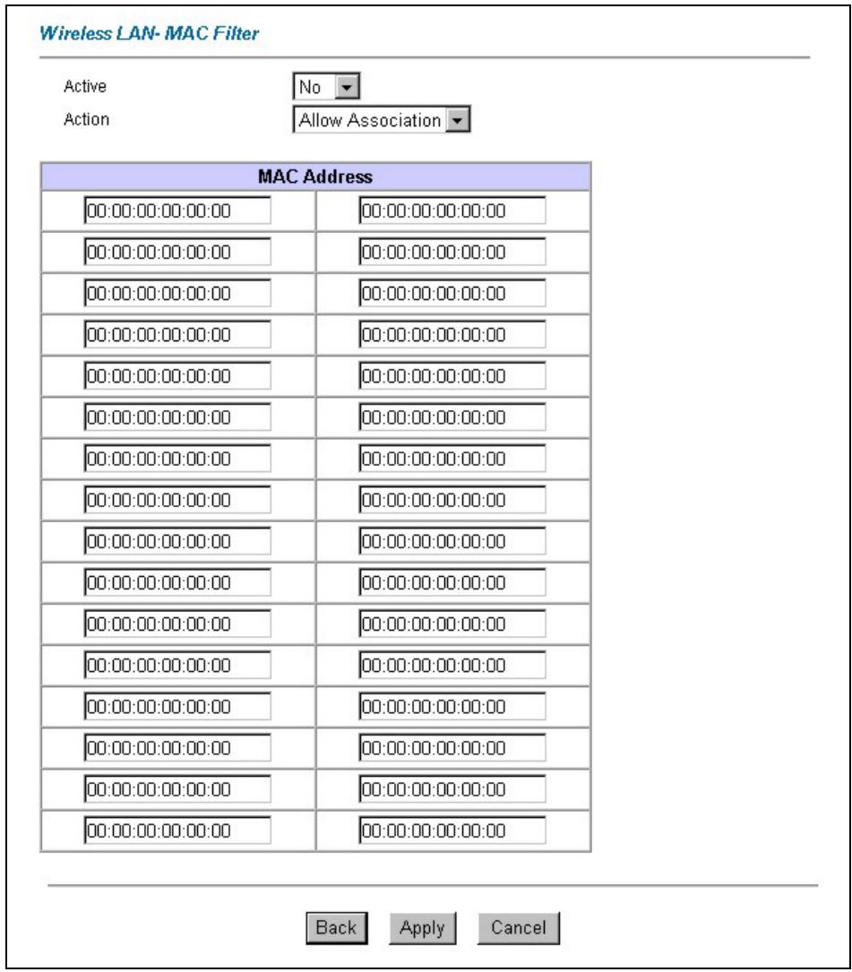
Figure 6-4 MAC Address Filter
The following table describes the fields in this menu.
Table 6-2 MAC Address Filter
| LABEL | DESCRIPTION |
| Active | Select Yes from the drop down list box to enable MAC address filtering |
| Action | Define the filter action for the list of MAC addresses in the MAC address filter table.Select Deny Association to block access to the router, MAC addresses not listed will be allowed to access the router. Select Allow Association to permit access to the router, MAC addresses not listed will be denied access to the router. |
| MAC Address | Enter the MAC addresses (in XX:XX:XX:XX:XX:XX format) of the wireless station that are allowed or denied access to the Prestige in these address fields. |
| Back | Click Back to go to the main wireless LAN setup screen. |
| Apply | Click Apply to save your changes back to the Prestige. |
| Cancel | Click Cancel to begin configuring this screen afresh. |
6.7 Network Authentication
You can set the Prestige and your network to authenticate a wireless station before the wireless station can communicate with the Prestige and the wired network to which the Prestige is connected.
6.7.1 EAP
EAP is an authentication protocol designed originally to run over PPP (Point-to-Point Protocol) frame in order to support multiple types of user authentication. By using EAP to interact with an EAP-compatible RADIUS server, the access point helps a wireless station and a RADIUS server to perform mutual authentication.
6.7.2 RADIUS
RADIUS is based on a client-sever model that supports authentication, authorization and accounting. The access point is the client and the server is the RADIUS server. The RADIUS server handles the following tasks:
- Authentication
Determines the identity of the users. - Authorization
Determines the network services available to authenticated users once they are connected to the network.
- Accounting
Keeps track of the client's network activity.
RADIUS is a simple package exchange in which your Prestige acts as a message relay between the wireless station and the network RADIUS server.
Types of RADIUS Messages
The following types of RADIUS messages are exchanged between the access point and the RADIUS server for user authentication:
- Access-Request
Sent by an access point requesting authentication. - Access-Reject
Sent by a RADIUS server rejecting access. - Access-Accept
Sent by a RADIUS server allowing access. - Access-Challenge
Sent by a RADIUS server requesting more information in order to allow access. The access point sends a proper response from the user and then sends another Access-Request message.
The following types of RADIUS messages are exchanged between the access point and the RADIUS server for user accounting:
- Accounting-Request
Sent by the access point requesting accounting.
• Accounting-Response
Sent by the RADIUS server to indicate that it has started or stopped accounting.
In order to ensure network security, the access point and the RADIUS server use a shared secret key, which is a password, they both know. The key is not sent over the network. In addition to the shared key, password information exchanged is also encrypted to protect the network from unauthorized access.
6.7.3 EAP Authentication Overview
EAP (Extensible Authentication Protocol) is an authentication protocol that runs on top of the IEEE802.1x transport mechanism in order to support multiple types of user authentication. By using EAP to interact with
an EAP-compatible RADIUS server, the access point helps a wireless station and a RADIUS server perform authentication.
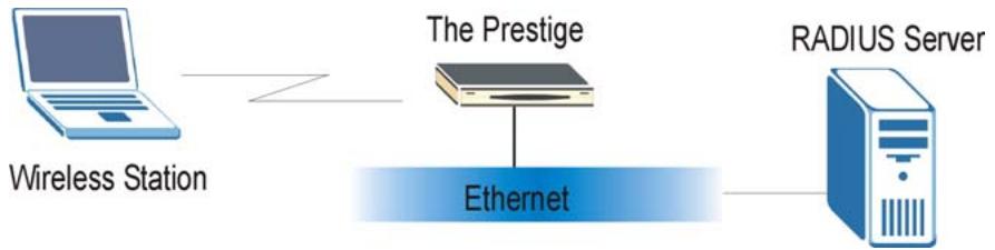
flowchart
graph LR
    A["Wireless Station"] --> B["The Prestige"]
    B --> C["Ethernet"]
    C --> D["RADIUS Server"]
Figure 6-5 EAP Authentication
The details below provide a general description of how IEEE 802.1x EAP authentication works. For an example list of EAP-MD5 authentication steps, see the IEEE 802.1x appendix.
Step 1. The wireless station sends a “start” message to the Prestige.
Step 2. The Prestige sends a “request identity” message to the wireless station for identity information.
Step 3. The wireless station replies with identity information, including username and password.
Step 4. The RADIUS server checks the user information against its user profile database and determines whether or not to authenticate the wireless station.
6.8 Configuring 802.1x
To change your Prestige's authentication settings, click Wireless LAN, 802.1x. The screen appears as shown.
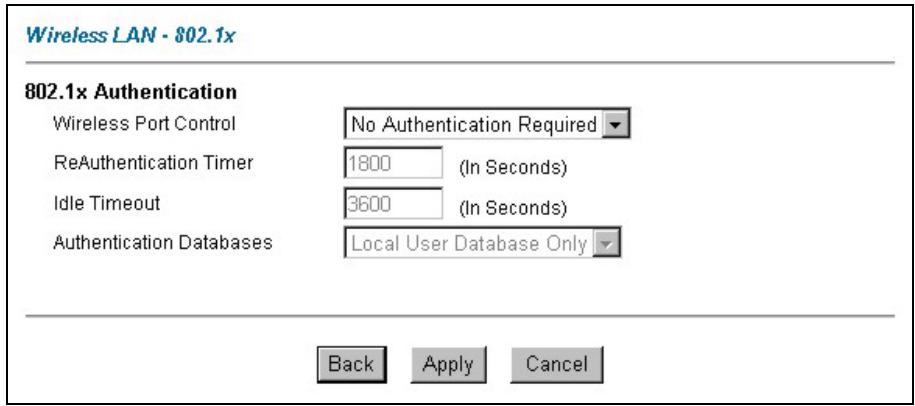
Figure 6-6 802.1x
The following table describes the fields in this screen.
Table 6-3 802.1x
| LABEL | DESCRIPTION |
| Wireless Port Control | To control wireless stations access to the wired network, select a control method from the drop-down list box. Choose fromNo Authentication Required, Authentication RequiredandNo Access Allowed.No Authentication Requiredallows all wireless stations access to the wired network without entering user names and passwords. This is the default setting.Authentication Requiredmeans that all wireless stations have to enter user names and passwords before access to the wired network is allowed.No Access Allowedblocks all wireless stations access to the wired network. |
| ReAuthentication Timer | Specify how often wireless stations have to reenter user names and passwords in order to stay connected. This field is activated only when you selectAuthentication Requiredin the Wireless Port Controlfield.Enter a time interval between 10 and 9999 seconds. The default time interval is1800 seconds (30 minutes).If wireless station authentication is done using a RADIUS server, the reauthentication timer on the RADIUS server has priority. |
| Idle Timeout | The Prestige automatically disconnects a wireless station from the wired network after a period of inactivity. The wireless station needs to enter the user name and password again before access to the wired network is allowed.This field is activated only when you selectAuthentication Requiredin the Wireless Port Controlfield. The default time interval is3600seconds (1 hour). |
Table 6-3 802.1x
| LABEL | DESCRIPTION |
| Authentication Databases | This field is activated only when you select Authentication Required in the Wireless Port Control field.The authentication database contains wireless station login information. The local user database is the built-in database on the Prestige. The RADIUS is an external server. Use this drop-down list box to select which database the Prestige should use (first) to authenticate a wireless station.Before you specify the priority, make sure you have set up the corresponding database(s) correctly.Select Local User Database Only to have the Prestige just check the built-in user database on the Prestige for a client's user name and password.Select RADIUS Only to have the Prestige just check the user database on the specified RADIUS server for a client's user name and password.Select Local first, then RADIUS to have the Prestige first check the user database on the Prestige for a client's user name and password. If the user name is not found, the Prestige checks the user database on the specified RADIUS server.Select RADIUS first, then Local to have the Prestige first check the user database on the specified RADIUS server for a client's user name and password. When the user name is not found or password does not match in the RADIUS server, the Prestige will not check the local user database and the authentication fails. If the Prestige cannot reach the RADIUS server, then the Prestige checks the local user database on the Prestige. |
| Back | Click Back to go to the main wireless LAN setup screen. |
| Apply | Click Apply to save these settings back to the Prestige. |
| Cancel | Click Cancel to begin configuring this screen again. |
6.9 Configuring Local User Authentication
By storing user profiles locally, your Prestige is able to authenticate wireless users without interacting with a network RADIUS server. However, there is a limit on the number of users you may authenticate in this way.
To change your Prestige's local user database, click Wireless LAN, Local User Database. The screen appears as shown.
Wireless LAN · Local User DataBase
| # | Active | User Name | Password |
| 1 | |||
| 2 | |||
| 3 | |||
| 4 | |||
| 5 | |||
| 6 | |||
| 7 | |||
| 8 | |||
| 9 | |||
| 10 | |||
| 11 | |||
| 12 | |||
| 13 | |||
| 14 | |||
| 15 | |||
| 16 | |||
| 17 | |||
| 18 | |||
| 19 | |||
| 20 | |||
| 21 | |||
| 22 | |||
| 23 | |||
| 24 | |||
| 25 | |||
| 26 | |||
| 27 | |||
| 28 | |||
| 29 | |||
| 30 | |||
| 31 | |||
| 32 |

Figure 6-7 Local User Database
The following table describes the fields in this screen.
Table 6-4 Local User Database
| LABEL | DESCRIPTION |
| # | This is the index number of a local user account. |
| Active | Select this check box to enable the user profile. |
| User Name | Enter the user name of the user profile. |
| Password | Enter a password up to 31 characters long for this user profile. |
| Back | Click Back to go to the main wireless LAN setup screen. |
| Apply | Click Apply to save these settings back to the Prestige. |
| Cancel | Click Cancel to begin configuring this screen again. |
6.10 Configuring RADIUS
Once you enable the EAP authentication, you need to specify the external sever for remote user authentication and accounting.
To set up your Prestige's RADIUS server settings, click WIRELESS LAN, RADIUS. The screen appears as shown.
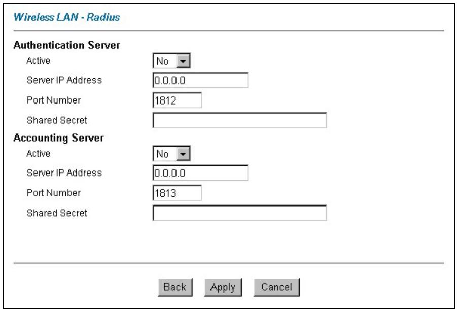
Figure 6-8 RADIUS
The following table describes the fields in this screen.
Table 6-5 RADIUS
| LABEL | DESCRIPTION |
| Authentication Server | |
| Active | Select Yes from the drop-down list box to enable user authentication through an external authentication server. |
| Server IP Address | Enter the IP address of the external authentication server in dotted decimal notation. |
| Port Number | The default port of the RADIUS server for authentication is 1812.You need not change this value unless your network administrator instructs you to do so with additional information. |
| Shared Secret | Enter a password (up to 31 alphanumeric characters) as the key to be shared between the external authentication server and the access points.The key is not sent over the network. This key must be the same on the external authentication server and Prestige. |
| Accounting Server | |
| Active | Select Yes from the drop-down list box to enable user authentication through an external accounting server. |
| Server IP Address | Enter the IP address of the external accounting server in dotted decimal notation. |
| Port Number | The default port of the RADIUS server for accounting is 1813.You need not change this value unless your network administrator instructs you to do so with additional information. |
| Shared Secret | Enter a password (up to 31 alphanumeric characters) as the key to be shared between the external accounting server and the access points.The key is not sent over the network. This key must be the same on the external accounting server and the Prestige. |
| Back | Click Back to go to the main wireless LAN setup screen. |
| Apply | Click Apply to save these settings back to the Prestige. |
| Cancel | Click Cancel to begin configuring this screen again. |
Chapter 7
WAN Setup
This chapter describes how to configure WAN settings.
7.1 WAN Overview
A WAN (Wide Area Network) is an outside connection to another network or the Internet.
See the Wizard Setup chapter for more information on the fields in the WAN screens.
7.2 Metric
The metric represents the "cost of transmission". A router determines the best route for transmission by choosing a path with the lowest "cost". RIP routing uses hop count as the measurement of cost, with a minimum of "1" for directly connected networks. The number must be between "1" and "15"; a number greater than "15" means the link is down. The smaller the number, the lower the "cost".
The metric sets the priority for the Prestige's routes to the Internet. If any two of the default routes have the same metric, the Prestige uses the following pre-defined priorities:
- Normal route: designated by the ISP (see section 7.5)
- Traffic-redirect route (see section 7.6)
- WAN-backup route, also called dial-backup (see section 7.6)
For example, if the normal route has a metric of "1" and the traffic-redirect route has a metric of "2" and dial-backup route has a metric of "3", then the normal route acts as the primary default route. If the normal route fails to connect to the Internet, the Prestige tries the traffic-redirect route next. In the same manner, the Prestige uses the dial-backup route if the traffic-redirect route also fails.
If you want the dial-backup route to take first priority over the traffic-redirect route or even the normal route, all you need to do is set the dial-backup route's metric to "1" and the others to "2" (or greater).
IP Policy Routing overrides the default routing behavior and takes priority over all of the routes mentioned above (see the IP Policy Routing chapter).
7.3 PPPoE Encapsulation
The Prestige supports PPPoE (Point-to-Point Protocol over Ethernet). PPPoE is an IETF Draft standard (RFC 2516) specifying how a personal computer (PC) interacts with a broadband modem (DSL, cable, wireless, etc.) connection. The PPPoE option is for a dial-up connection using PPPoE.
For the service provider, PPPoE offers an access and authentication method that works with existing access control systems (for example Radius). PPPoE provides a login and authentication method that the existing Microsoft Dial-Up Networking software can activate, and therefore requires no new learning or procedures for Windows users.
One of the benefits of PPPoE is the ability to let you access one of multiple network services, a function known as dynamic service selection. This enables the service provider to easily create and offer new IP services for individuals.
Operationally, PPPoE saves significant effort for both you and the ISP or carrier, as it requires no specific configuration of the broadband modem at the customer site.
By implementing PPPoE directly on the Prestige (rather than individual computers), the computers on the LAN do not need PPPoE software installed, since the Prestige does that part of the task. Furthermore, with NAT, all of the LANs' computers will have access.
7.4 Traffic Shaping
Traffic Shaping is an agreement between the carrier and the subscriber to regulate the average rate and “burstiness” or fluctuation of data transmission over an ATM network. This agreement helps eliminate congestion, which is important for transmission of real time data such as audio and video connections.
Peak Cell Rate (PCR) is the maximum rate at which the sender can send cells. This parameter may be lower (but not higher) than the maximum line speed. 1 ATM cell is 53 bytes (424 bits), so a maximum speed of 832 Kbps gives a maximum PCR of 1962 cells/sec. This rate is not guaranteed because it is dependent on the line speed.
Sustained Cell Rate (SCR) is the mean cell rate of a bursty, on-off traffic source that can be sent at the peak rate, and a parameter for burst-type traffic. SCR may not be greater than the PCR; the system default is 0 cells/sec.
Maximum Burst Size (MBS) is the maximum number of cells that can be sent at the PCR. After MBS is reached, cell rates fall below SCR until cell rate averages to the SCR again. At this time, more cells (up to the MBS) can be sent at the PCR again.
If the PCR, SCR or MBS is set to the default of “0”, the system will assign a maximum value that correlates to your upstream line rate.
The following figure illustrates the relationship between PCR, SCR and MBS.
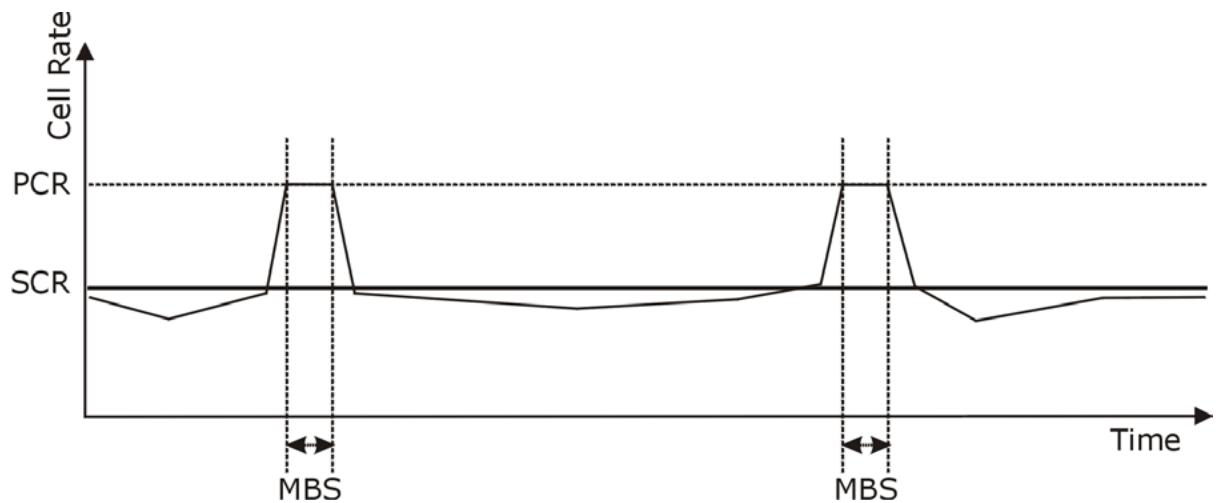
line
| Time Segment | Cell Rate | | ------------ | --------- | | MBS | 1.0 | | Midpoint | 1.0 | | Midpoint | 0.5 | | Midpoint | 0.5 | | Midpoint | 0.5 | | Midpoint | 1.0 | | Midpoint | 1.0 | | Midpoint | 0.5 | | Midpoint | 0.5 | | Midpoint | 0.5 | | Midpoint | 0.5 | | Midpoint | 1.0 | | Midpoint | 1.0 | | Midpoint | 0.5 | | Midpoint | 0.5 | | Midpoint | 0.5 | | Midpoint | 0.59 |Figure 7-1 Example of Traffic Shaping
7.5 Configuring WAN Setup
To change your Prestige's WAN remote node settings, click WAN, WAN Setup. The screen differs by the encapsulation.
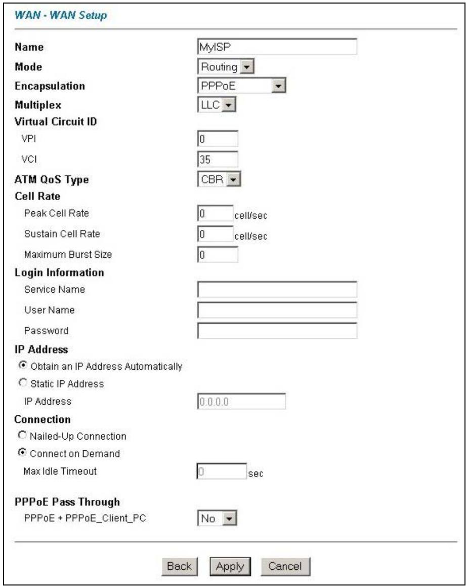
Figure 7-2 WAN Setup
The following table describes the fields in this screen.
Table 7-1 WAN Setup
| LABEL | DESCRIPTION |
| Name | Enter the name of your Internet Service Provider, e.g., MyISP. This information is for identification purposes only. |
| Mode | Select Routing (default) from the drop-down list box if your ISP allows multiple computers to share an Internet account. Otherwise select Bridge. |
| Encapsulation | Select the method of encapsulation used by your ISP from the drop-down list box. Choices vary depending on the mode you select in the Mode field. If you select Bridge in the Mode field, select either PPPoA or RFC 1483. If you select Routing in the Mode field, select PPPoA, RFC 1483, ENET ENCAP or PPPoE. |
| Multiplex | Select the method of multiplexing used by your ISP from the drop-down list. Choices are VC or LLC. |
| Virtual Circuit ID | VPI (Virtual Path Identifier) and VCI (Virtual Channel Identifier) define a virtual circuit. Refer to the appendix for more information. |
| VPI | The valid range for the VPI is 0 to 255. Enter the VPI assigned to you. |
| VCI | The valid range for the VCI is 32 to 65535 (0 to 31 is reserved for local management of ATM traffic). Enter the VCI assigned to you. |
| ATM QoS Type | Select CBR (Continuous Bit Rate) to specify fixed (always-on) bandwidth for voice or data traffic. Select UBR (Unspecified Bit Rate) for applications that are non-time sensitive, such as e-mail. Select VBR (Variable Bit Rate) for bursty traffic and bandwidth sharing with other applications. |
| Cell Rate | Cell rate configuration often helps eliminate traffic congestion that slows transmission of real time data such as audio and video connections. |
| Peak Cell Rate | Divide the DSL line rate (bps) by 424 (the size of an ATM cell) to find the Peak Cell Rate (PCR). This is the maximum rate at which the sender can send cells. Type the PCR here. |
| Sustain Cell Rate | The Sustain Cell Rate (SCR) sets the average cell rate (long-term) that can be transmitted. Type the SCR, which must be less than the PCR. |
Table 7-1 WAN Setup
| LABEL | DESCRIPTION |
| Maximum Burst Size | Maximum Burst Size (MBS) refers to the maximum number of cells that can be sent at the peak rate. Type the MBS, which is less than 65535. |
| Login Information | (PPPoA and PPPoE encapsulation only) |
| Service Name | (PPPoE only) Type the name of your PPPoE service here. |
| User Name | Enter the user name exactly as your ISP assigned. If assigned a name in the formuser@domainwhere domain identifies a service name, then enter both components exactly as given. |
| Password | Enter the password associated with the user name above. |
| IP Address | This option is available if you selectRoutingin theModefield.A static IP address is a fixed IP that your ISP gives you. A dynamic IP address is not fixed; the ISP assigns you a different one each time you connect to the Internet. The Single User Account feature can be used with either a dynamic or static IP address.SelectObtain an IP Address Automaticallyif you have a dynamic IP address; otherwise selectStatic IP Addressand type your ISP assigned IP address in the IPAddressfield below. |
| Connection(PPPoA and PPPoE encapsulation only) | The schedule rule(s) in SMT menu 26 have priority over yourConnectionsettings. |
| Nailed-Up Connection | SelectNailed-Up Connectionwhen you want your connection up all the time. The Prestige will try to bring up the connection automatically if it is disconnected. |
| Connect on Demand | SelectConnect on Demandwhen you don't want the connection up all the time and specify an idle time-out in theMax Idle Timeoutfield. |
| Max Idle Timeout | Specify an idle time-out in theMax Idle Timeoutfield when you selectConnect onDemand. The default setting is 0, which means the Internet session will not timeout. |
| PPPoE Pass Through | This field is available when you selectPPPoE encapsulation. |
Table 7-1 WAN Setup
| LABEL | DESCRIPTION |
| PPPoE + PPPoE_Client_PC (PPPoE encapsulation only) | In addition to the Prestige's built-in PPPoE client, you can enable PPPoE pass through to allow up to ten hosts on the LAN to use PPPoE client software on their computers to connect to the ISP via the Prestige. Each host can have a separate account and a public WAN IP address.PPPoE pass through is an alternative to NAT for application where NAT is not appropriate.Disable PPPoE pass through if you do not need to allow hosts on the LAN to use PPPoE client software on their computers to connect to the ISP. |
| Subnet Mask (ENET ENCAP encapsulation only) | Enter a subnet mask in dotted decimal notation.Refer to the Subnetting appendix in the to calculate a subnet mask If you are implementing subnetting. |
| ENET ENCAP Gateway (ENET ENCAP encapsulation only) | You must specify a gateway IP address (supplied by your ISP) when you select ENET ENCAP in the Encapsulation field |
| Back | Click Back to return to the previous screen. |
| Apply | Click Apply to save the changes. |
| Cancel | Click Cancel to begin configuring this screen afresh. |
7.6 WAN Backup
The CON/AUX port on the Prestige 652H/HW or the Dial Backup port on the Prestige 652 can be used in reserve, as a traditional dial-up connection should the WAN port connection fail. To set up the auxiliary port (AUX) for the Prestige 652H/HW for use in the event that the regular WAN connection is dropped, first make sure you have set up the switch and port connection (see the Compact Guide).
7.7 Traffic Redirect on the LAN
Traffic redirect forwards LAN traffic to a backup gateway when the Prestige cannot connect to the Internet. An example is shown in the figure below.
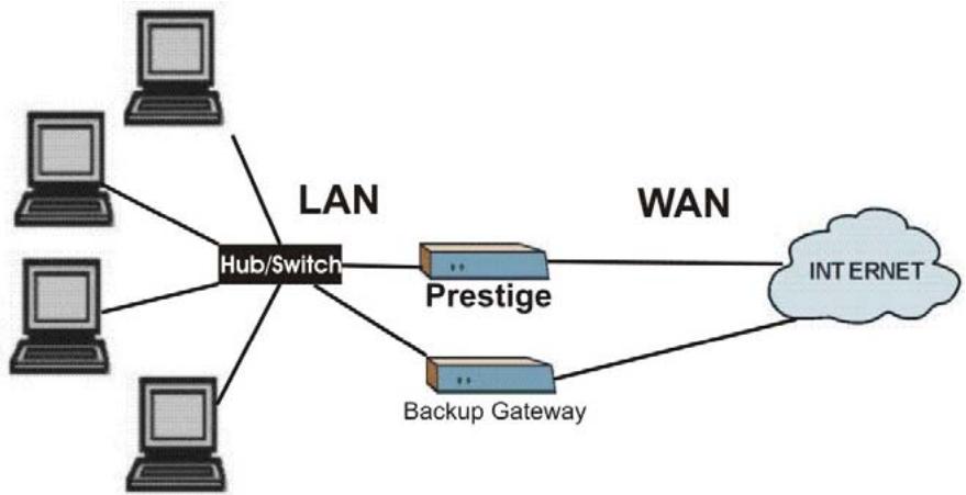
flowchart
graph TD
    A["Client 1"] --> B["Hub/Switch"]
    C["Client 2"] --> B
    D["Client 3"] --> B
    E["Client 4"] --> B
    B --> F["Prestige"]
    B --> G["Backup Gateway"]
    F --> H["WAN"]
    G --> H
    H --> I["INTERNET"]
    style B fill:#000,stroke:#fff,color:#fff
Figure 7-3 Traffic Redirect Setup Example
7.8 Traffic Redirect on the WAN
Traffic redirect forwards WAN traffic to a backup gateway when the Prestige cannot connect to the Internet through its normal gateway. Connect the backup gateway on the WAN so that the Prestige still provides firewall protection.
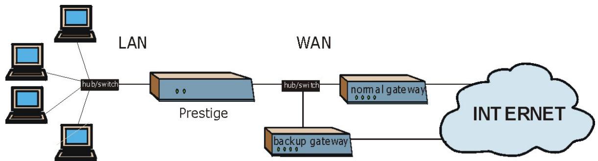
flowchart
graph LR
    A["Computer"] -->|hub/switch| B["Prestige"]
    C["Computer"] -->|hub/switch| B
    B -->|hub/switch| D["normal gateway"]
    D --> E["INTERNET"]
    F["Backup gateway"] --> D
    style A fill:#f9f,stroke:#333
    style C fill:#f9f,stroke:#333
    style B fill:#ccf,stroke:#333
    style D fill:#ccf,stroke:#333
    style E fill:#cfc,stroke:#333
Figure 7-4 Traffic Redirect WAN Setup
The following network topology allows you to avoid triangle route security issues when the backup gateway is connected to the LAN or DMZ. Use IP alias to configure the LAN into two or three logical networks with the Prestige itself as the gateway for each LAN network. Put the protected LAN in one subnet (Subnet 1 in the following figure) and the backup gateway in another subnet (Subnet 2). Configure a LAN to LAN/Prestige firewall rule that forwards packets from the protected LAN (Subnet 1) to the backup gateway (Subnet 2).
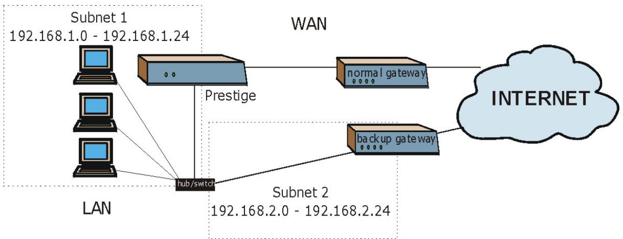
flowchart
graph TD
    A["LAN"] --> B["Subnet 1 192.168.1.0 - 192.168.1.24"]
    A --> C["Subnet 2 192.168.2.0 - 192.168.2.24"]
    D["Subnet 2"] --> E["hub/switch"]
    F["Internet"] --> G["normal gateway"]
    G --> H["Prestige"]
    I["back up gateway"] --> J["Subnet 2"]
    style A fill:#f9f,stroke:#333
    style B fill:#ccf,stroke:#333
    style C fill:#ccf,stroke:#333
    style D fill:#ccf,stroke:#333
    style E fill:#cfc,stroke:#333
    style F fill:#cfc,stroke:#333
    style G fill:#fcc,stroke:#333
    style H fill:#cff,stroke:#333
Figure 7-5 Traffic Redirect LAN Setup
7.9 Configuring WAN Backup
To change your Prestige's WAN backup settings, click WAN, then WAN Backup. The screen appears as shown.
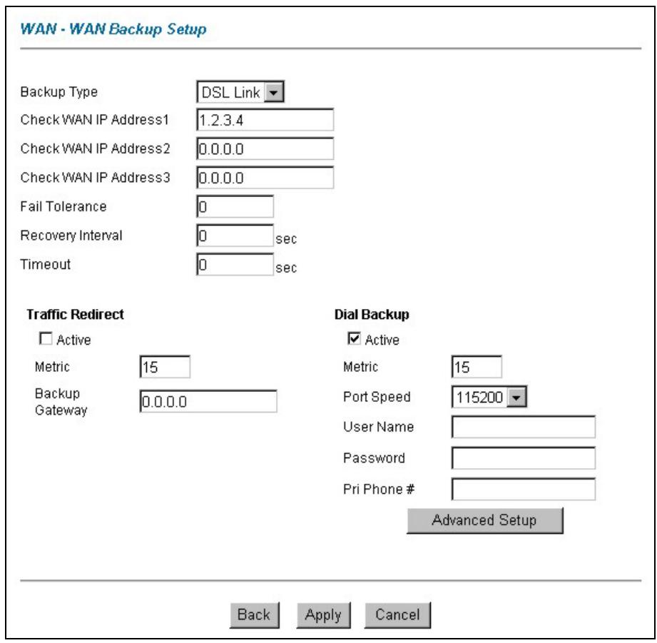
Figure 7-6 WAN Backup
The following table describes the fields in this screen.
Table 7-2 WAN Backup
| LABEL | DESCRIPTION |
| Backup Type | Select the method that the Prestige uses to check the DSL connection.Select DSL Link to have the Prestige check the DSL connection's physical layer.Select ICMP to have the Prestige periodically ping the IP addresses configured in the Check WAN IP Address fields. |
Table 7-2 WAN Backup
| LABEL | DESCRIPTION |
| Check WAN IP Address1-3 | Configure this field to test your Prestige's WAN accessibility. Type the IP address of a reliable nearby computer (for example, your ISP's DNS server address).When using a WAN backup connection, the Prestige periodically pings the addresses configured here and uses the other WAN backup connection (if configured) if there is no response. |
| Fail Tolerance | Type the number of times (2 recommended) that your Prestige may ping the IP addresses configured in the Check WAN IP Address field without getting a response before switching to a WAN backup connection (or a different WAN backup connection). |
| Recovery Interval | When the Prestige is using a lower priority connection (usually a WAN backup connection), it periodically checks to whether or not it can use a higher priority connection.Type the number of seconds (30 recommended) for the Prestige to wait between checks. Allow more time if your destination IP address handles lots of traffic. |
| Timeout | Type the number of seconds (3 recommended) for your Prestige to wait for a ping response from one of the IP addresses in the Check WAN IP Address field before timing out the request. The WAN connection is considered "down" after the Prestige times out the number of times specified in the Fail Tolerance field.Use a higher value in this field if your network is busy or congested. |
| Traffic Redirect | |
| Active | Select this check box to have the Prestige use traffic redirect if the normal WAN connection goes down. |
| Metric | This field sets this route's priority among the routes the Prestige uses.The metric represents the "cost of transmission". A router determines the best route for transmission by choosing a path with the lowest "cost". RIP routing uses hop count as the measurement of cost, with a minimum of "1" for directly connected networks. The number must be between "1" and "15"; a number greater than "15" means the link is down. The smaller the number, the lower the "cost". |
| Backup Gateway | Type the IP address of your backup gateway in dotted decimal notation. The Prestige automatically forwards traffic to this IP address if the Prestige's Internet connection terminates. |
| Dial Backup | |
| Active | Select this check box to turn on dial backup. |
Table 7-2 WAN Backup
| LABEL | DESCRIPTION |
| Metric | This field sets this route's priority among the three routes the Prestige uses (normal, traffic redirect and dial backup). Type a number (1 to 15) to set the priority of the dial backup route for data transmission. The smaller the number, the higher the priority.If the three routes have the same metrics, the priority of the routes is as follows: WAN, Traffic Redirect, Dial Backup. |
| Port Speed | Use the drop-down list box to select the speed of the connection between the dial backup port and the external device. Available speeds are: 9600, 19200, 38400, 57600, 115200 or 230400 bps. |
| User Name | Type the login name assigned by your ISP. |
| Password | Type the password assigned by your ISP. |
| Pri Phone # | Type the first (primary) phone number from the ISP for this remote node. Some areas require dialing the pound sign # before the phone number for local calls. Include a # symbol at the beginning of the phone numbers as required. |
| Advanced Setup | Click this button to display the Advanced Setup screen and edit more details of your WAN backup setup. |
| Back | Click Back to return to the previous screen. |
| Apply | Click Apply to save the changes. |
| Cancel | Click Cancel to begin configuring this screen afresh. |
7.10 Configuring Advanced WAN Backup
To edit your Prestige's advanced WAN backup settings, click WAN, WAN Backup and then the Advanced Setup button. The screen appears as shown.
WAN - WAN Backup Setup- WAN Backup Advanced
Basic
Login Name
Password
Retype to Confirm
Authentication Type
Primary Phone Number
Secondary Phone Number
Dial Backup Port Speed
AT Command Initial String
Advanced Modem Setup
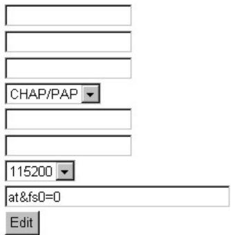
TCP/IP Options
Metric
15
Enable SUA
Enable RIP
RIP Version
RIP Direction
Enable Multicast
Multicast
IGMP-v2
PPP Options
Encapsulation
Standard PPP
Compression
Connection
○ Nailed-Up Connection
Connect on Demand
Max Idle Timeout
100 sec
Budget
Allocated Budget
0 min 0 hr
Period

Figure 7-7 Advanced WAN Backup
The following table describes the fields in this screen.
Table 7-3 Advanced WAN Backup
| LABEL | DESCRIPTION |
| Basic | |
| Login Name | Type the login name assigned by your ISP. |
| Password | Type the password assigned by your ISP. |
| Retype to Confirm | Type your password again to make sure that you have entered is correctly. |
| Authentication Type | Use the drop-down list box to select an authentication protocol for outgoing calls. Options are:CHAP/PAP - Your Prestige accepts either CHAP or PAP when requested by this remote node.CHAP - Your Prestige accepts CHAP only.PAP - Your Prestige accept PAP only. |
| Primary/ Secondary Phone Number | Type the first (primary) phone number from the ISP for this remote node. If the primary phone number is busy or does not answer, your Prestige dials the secondary phone number if available. Some areas require dialing the pound sign # before the phone number for local calls. Include a # symbol at the beginning of the phone numbers as required. |
| Dial Backup Port Speed | Use the drop-down list box to select the speed of the connection between the dial backup port and the external device. Available speeds are: 9600, 19200, 38400, 57600, 115200 or 230400 bps. |
| AT Command Initial String | Type the AT command string to initialize the WAN device. Consult the manual of your WAN device connected to your dial backup port for specific AT commands. |
| Advanced Modem Setup | Click the Edit button to display the Advanced Modem Setup screen and edit the details of your dial backup setup. |
| TCP/IP Options | |
| Metric | This field sets this route's priority among the three routes the Prestige uses (normal, traffic redirect and dial backup). Type a number (1 to 15) to set the priority of the dial backup route for data transmission. The smaller the number, the higher the priority.If the three routes have the same metrics, the priority of the routes is as follows: WAN, Traffic Redirect, Dial Backup. |
Table 7-3 Advanced WAN Backup
| LABEL | DESCRIPTION |
| Enable SUA | Network Address Translation (NAT) allows the translation of an Internet protocol address used within one network to a different IP address known within another network.SUA (Single User Account) is a subset of NAT that supports two types of mapping: Many-to-One and Server. When you select this option the Prestige will use Address Mapping Set 255 (see the NAT chapter for more information). |
| Enable RIP | Select this check box to turn on RIP (Routing Information Protocol), which allows a router to exchange routing information with other routers. |
| RIP Version | The RIP Version field controls the format and the broadcasting method of the RIP packets that the Prestige sends (it recognizes both formats when receiving).Choose RIP-1, RIP-2B or RIP-2M.RIP-1 is universally supported; but RIP-2 carries more information. RIP-1 is probably adequate for most networks, unless you have an unusual network topology. Both RIP-2B and RIP-2M sends the routing data in RIP-2 format; the difference being that RIP-2B uses subnet broadcasting while RIP-2M uses multicasting. Multicasting can reduce the load on non-router machines since they generally do not listen to the RIP multicast address and so will not receive the RIP packets. However, if one router uses multicasting, then all routers on your network must use multicasting, also. |
| RIP Direction | RIP (Routing Information Protocol) allows a router to exchange routing information with other routers. The RIP Direction field controls the sending and receiving of RIP packets.Choose Both, In Only or Out Only.When set to Both or Out Only, the Prestige will broadcast its routing table periodically.When set to Both or In Only, the Prestige will incorporate RIP information that it receives. |
| Enable Multicast | Select this check box to turn on IGMP (Internet Group Multicast Protocol). IGMP is a network-layer protocol used to establish membership in a Multicast group - it is not used to carry user data. |
| Multicast | Select IGMP-v1 or IGMP-v2. IGMP version 2 (RFC 2236) is an improvement over version 1 (RFC 1112) but IGMP version 1 is still in wide use. If you would like to read more detailed information about interoperability between IGMP version 2 and version 1, please see sections 4 and 5 of RFC 2236. |
| PPP Options |
Table 7-3 Advanced WAN Backup
| LABEL | DESCRIPTION |
| Encapsulation | Select CISCO PPP from the drop-down list box if your backup WAN device uses Cisco PPP encapsulation; otherwise select Standard PPP. |
| Compression | Select this check box to enable stac compression. |
| Connection | |
| Nailed-Up Connection | Select Nailed-Up Connection when you want your connection up all the time. The Prestige will try to bring up the connection automatically if it is disconnected. |
| Connect on Demand | Select Connect on Demand when you don't want the connection up all the time and specify an idle time-out in the Max Idle Timeout field. |
| Max Idle Timeout | Specify an idle time-out in the Max Idle Timeout field when you select Connect on Demand. The default setting is 0, which means the Internet session will not timeout. |
| Budget | The configuration in the Budget fields has priority over your Connection settings. |
| Allocate Budget | Type the amount of time (in minutes) that the dial backup connection can be used during the time configured in the Period field. Set an amount that is less than the time period configured in the Period field. If you set the Allocated Budget to 0, you will not be able to use the dial backup connection. |
| Period | Type the time period (in hours) for how often the budget should be reset. For example, to allow calls to this remote node for a maximum of 10 minutes every hour, set the Allocated Budget to 10 (minutes) and the Period to 1 (hour). If you set the Period to 0, there is no budget control and the Prestige uses the Connection settings. |
| Back | Click Back to return to the previous screen. |
| OK | Click OK to return to the previous screen, then click Apply to save the changes. |
| Cancel | Click Cancel to begin configuring this screen afresh. |
7.11 AT Command Strings
For regular telephone lines, the default “Dial” string tells the modem that the line uses tone dialing. “ATDT” is the command for a switch that requires tone dialing. If your switch requires pulse dialing, change the string to “ATDP”.
For ISDN lines, there are many more protocols and operational modes. Please consult the documentation of your TA. You may need additional commands in both “Dial” and “Init” strings.
7.12 DTR Signal
The majority of WAN devices default to hanging up the current call when the DTR (Data Terminal Ready) signal is dropped by the DTE. When the “Drop DTR When Hang Up” check box is selected, the Prestige uses this hardware signal to force the WAN device to hang up, in addition to issuing the drop command “ATH”.
7.13 Response Strings
The response strings tell the Prestige the tags, or labels, immediately preceding the various call parameters sent from the WAN device. The response strings have not been standardized; please consult the documentation of your WAN device to find the correct tags.
7.14 Configuring Advanced Modem Setup
To configure settings for your backup WAN modem, click WAN, WAN Backup and then the Advanced Setup button. The Advanced Setup screen displays, click the Edit button to open the Advanced Modem Setup screen as shown next.
Consult the manual of your WAN device connected to your dial backup port for specific AT commands.
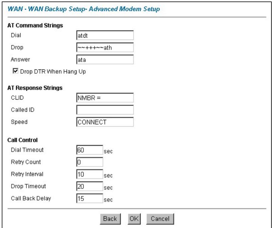
Figure 7-8 Advanced Modem Setup
The following table describes the fields in this screen.
Table 7-4 Advanced Modem Setup
| LABEL | DESCRIPTION |
| AT Command Strings | |
| Dial | Type the AT Command string to make a call. Example: atdt |
| Drop | Type the AT Command string to drop a call. "~" represents a one second wait, for example, "~~++~~ath" can be used if your modem has a slow response time. |
| Answer | Type the AT Command string to answer a call. Example: ata |
| Drop DTR When Hang Up | Select this check box to have the Prestige drop the DTR (Data Terminal Ready) signal after the "AT Command String: Drop" is sent out. |
Table 7-4 Advanced Modem Setup
| LABEL | DESCRIPTION |
| AT Response Strings | |
| CLID | Type the keyword that precedes the CLID (Calling Line Identification) in the AT response string. This lets the Prestige capture the CLID in the AT response string that comes from the WAN device. CLID is required for CLID authentication. Example: NMBR |
| Called ID | Type the keyword preceding the dialed number. |
| Speed | Type the keyword preceding the connection speed. Example: CONNECT |
| Call Control | |
| Dial Timeout | Type a number of seconds for the Prestige to try to set up an outgoing call before timing out (stopping). Example: 60 |
| Retry Count | Type a number of times for the Prestige to retry a busy or no-answer phone number before blacklisting the number. Example: 0 |
| Retry Interval | Type a number of seconds for the Prestige to wait before trying another call after a call has failed. This applies before a phone number is blacklisted. Example: 10 |
| Drop Timeout | Type the number of seconds for the Prestige to wait before dropping the DTR signal if it does not receive a positive disconnect confirmation. Example: 20 |
| Call Back Delay | Type a number of seconds for the Prestige to wait between dropping a callback request call and dialing the corresponding callback call. Example: 15 |
| Back | Click Back to return to the previous screen. |
| OK | Click OK to return to the previous screen, then click OK to return to the next previous screen and click Apply to save the changes. |
| Cancel | Click Cancel to begin configuring this screen afresh. |
Part III:
NAT, Dynamic DNS and Time Zone
This part covers NAT (Network Address Translation), dynamic DNS (Domain Name Sever) and Time Zone setup.
Chapter 8
Network Address Translation (NAT)
Screens
This chapter discusses how to configure NAT on the Prestige.
8.1 NAT Overview
NAT (Network Address Translation - NAT, RFC 1631) is the translation of the IP address of a host in a packet, for example, the source address of an outgoing packet, used within one network to a different IP address known within another network.
8.1.1 NAT Definitions
Inside/outside denotes where a host is located relative to the Prestige, for example, the computers of your subscribers are the inside hosts, while the web servers on the Internet are the outside hosts.
Global/local denotes the IP address of a host in a packet as the packet traverses a router, for example, the local address refers to the IP address of a host when the packet is in the local network, while the global address refers to the IP address of the host when the same packet is traveling in the WAN side.
Note that inside/outside refers to the location of a host, while global/local refers to the IP address of a host used in a packet. Thus, an inside local address (ILA) is the IP address of an inside host in a packet when the packet is still in the local network, while an inside global address (IGA) is the IP address of the same inside host when the packet is on the WAN side. The following table summarizes this information.
Table 8-1 NAT Definitions
| ITEM | DESCRIPTION |
| Inside | This refers to the host on the LAN. |
| Outside | This refers to the host on the WAN. |
| Local | This refers to the packet address (source or destination) as the packet travels on the LAN. |
| Global | This refers to the packet address (source or destination) as the packet travels on the WAN. |
NAT never changes the IP address (either local or global) of an outside host.
8.1.2 What NAT Does
In the simplest form, NAT changes the source IP address in a packet received from a subscriber (the inside local address) to another (the inside global address) before forwarding the packet to the WAN side. When the response comes back, NAT translates the destination address (the inside global address) back to the inside local address before forwarding it to the original inside host. Note that the IP address (either local or global) of an outside host is never changed.
The global IP addresses for the inside hosts can be either static or dynamically assigned by the ISP. In addition, you can designate servers, for example, a web server and a telnet server, on your local network and make them accessible to the outside world. Although you can make designated servers on the LAN accessible to the outside world, it is strongly recommended that you attach those servers to the DMZ port instead. If you do not define any servers (for Many-to-One and Many-to-Many Overload mapping – see Table 8-2), NAT offers the additional benefit of firewall protection. With no servers defined, your Prestige filters out all incoming inquiries, thus preventing intruders from probing your network. For more information on IP address translation, refer to RFC 1631, The IP Network Address Translator (NAT).
8.1.3 How NAT Works
Each packet has two addresses – a source address and a destination address. For outgoing packets, the ILA (Inside Local Address) is the source address on the LAN, and the IGA (Inside Global Address) is the source address on the WAN. For incoming packets, the ILA is the destination address on the LAN, and the IGA is the destination address on the WAN. NAT maps private (local) IP addresses to globally unique ones required for communication with hosts on other networks. It replaces the original IP source address (and TCP or UDP source port numbers for Many-to-One and Many-to-Many Overload NAT mapping) in each packet and then forwards it to the Internet. The Prestige keeps track of the original addresses and port numbers so incoming reply packets can have their original values restored. The following figure illustrates this.
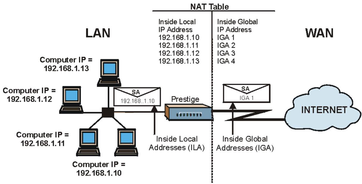
flowchart
graph TD
    subgraph LAN
        A["Computer IP = 192.168.1.13"] --> B["SA"]
        C["Computer IP = 192.168.1.12"] --> B
        D["Computer IP = 192.168.1.11"] --> E["Computer IP = 192.168.1.10"]
        F["Computer IP = 192.168.1.10"] --> G["SA"]
        H["Computer IP = 192.168.1.10"] --> I["SA"]
        J["Computer IP = 192.168.1.10"] --> K["SA"]
    end
    subgraph WAN
        L["SA"]
        M["IGA 1"] --> N["SA"]
        O["Internet"] --> P["SA"]
        Q["SA"]
        R["SA"]
        S["SA"]
        T["SA"]
        U["SA"]
        V["SA"]
        W["SA"]
        X["SA"]
        Y["SA"]
        Z["SA"]
        AA["SA"]
        AB["SA"]
        AC["SA"]
        AD["SA"]
    end
    style LAN fill:#f9f,stroke:#333
    style WAN fill:#ccf,stroke:#333
    note right of LAN
        Inside Local IP Address
        Inside IP Address
        IGA 1
        IGA 2
        IGA 3
        IGA 4
    end
    note right of LAN
        Inside Local Addresses (ILA)
        Inside Global Addresses (IGA)
    end
Figure 8-1 How NAT Works
8.1.4 NAT Application
The following figure illustrates a possible NAT application, where three inside LANs (logical LANs using IP Alias) behind the Prestige can communicate with three distinct WAN networks. More examples follow at the end of this chapter.
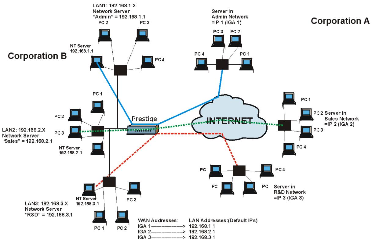
flowchart
```mermaid
graph TD
    subgraph Corporation A
        A1["NT Server 192.168.1.1"] --> A2["PC 1"]
        A2 --> A3["PC 2"]
        A3 --> A4["PC 3"]
        A4 --> A5["PC 4"]
        A5 --> A6["PC 1"]
        A6 --> A7["PC 2"]
        A7 --> A8["PC 3"]
        A8 --> A9["PC 4"]
        A9 --> A10["PC 1"]
        A10 --> A11["PC 2"]
        A11 --> A12["PC 3"]
        A12 --> A13["PC 4"]
        A13 --> A14["PC 1"]
        A4 --> A5
        A5 --> A6
        A6 --> A7
        A7 --> A8
        A8 --> A9
        A9 --> A10
        A10 --> A11
        A11 --> A12
        A12 --> A13
        A13 --> A14
        A14 --> A15["PC 1"]
        A15 --> A16["PC 2"]
        A16 --> A17["PC 3"]
        A17 --> A18["PC 4"]
        A18 --> A19["PC 1"]
        A19 --> A20["PC 2"]
        A20 --> A21["PC 3"]
        A21 --> A22["PC 4"]
        A22 --> A23["PC 1"]
        A23 --> A24["PC 2"]
        A24 --> A25["PC 3"]
        A25 --> A26["PC 4"]
        A26 --> A27["PC 1"]
        A27 --> A28["PC 2"]
        A28 --> A29["PC 3"]
        A29 --> A30["PC 4"]
        A30 --> A31["PC 1"]
        A31 --> A32["PC 2"]
        A32 --> A33["PC 3"]
        A33 --> A34["PC 4"]
        A34 --> A35["PC 1"]
        A35 --> A36["PC 2"]
        A36 --> A37["PC 3"]
        A37 --> A38["PC 4"]
        A38 --> A39["PC 1"]
        A39 --> A40["PC 2"]
        A40 --> A41["PC 3"]
        A41 --> A42["PC 4"]
        A42 --> A43["PC 1"]
        A43 --> A44["PC 2"]
        A44 --> A45["PC 3"]
        A45 --> A46["PC 4"]
        A46 --> A47["PC 1"]
        A47 --> A48["PC 2"]
        A48 --> A49["PC 3"]
        A49 --> A50["PC 4"]
    end

    subgraph Enterprise
        Enterprise((INTERNET))
            Enterprise
            Enterprise
            Enterprise
            Enterprise
            Enterprise
            Enterprise
            Enterprise
            Enterprise
            Enterprise
            Enterprise
            Enterprise
            Enterprise
            Enterprise
            Enterprise
            Enterprise
            Enterprise
            Enterprise
            Enterprise
            Enterprise
            Enterprise
            Enterprise
            Enterprise
            Enterprise
            Enterprise
            Enterprise
            Enterprise
            Enterprise
            Enterprise
            Enterprise
            Enterprise
            Enterprise
            Enterprise
            Enterprise
            Enterprise
    end

    style Enterprise fill:#f9f,stroke:#333,stroke-width:2px
    note right of Enterprise:
        LAN1::LAN1:LAN1.X, "Admin" = LAN1.1.
        LAN2::LAN2:LAN2.X, "Sales" = LAN2.1.
        LAN3::LAN3:LAN3.X, "R&D" = LAN3.1.
    end

    Note: WAN Addresses: IGA 1→LAN Addresses: Default IPs; IGA 2→LAN Addresses: Default IPs; IGA 3→LAN Addresses: Default IPs.

    %% Legend:
    PC1["PC 1"] to_PC4["PC 4"] and_PC5["PC 5"] are part of the diagram; all values in the table represent the same IP address and IGA value for each client.
Figure 8-2 NAT Application With IP Alias
8.1.5 NAT Mapping Types
NAT supports five types of IP/port mapping. They are:
- One to One: In One-to-One mode, the Prestige maps one local IP address to one global IP address.
- Many to One: In Many-to-One mode, the Prestige maps multiple local IP addresses to one global IP address. This is equivalent to SUA (for instance, PAT, port address translation), ZyXEL's Single User Account feature that previous ZyXEL routers supported (the SUA Only option in today's routers).
- Many to Many Overload: In Many-to-Many Overload mode, the Prestige maps the multiple local IP addresses to shared global IP addresses.
-
Many-to-Many No Overload: In Many-to-Many No Overload mode, the Prestige maps each local IP address to a unique global IP address.
-
Server: This type allows you to specify inside servers of different services behind the NAT to be accessible to the outside world although, it is highly recommended that you use the DMZ port for these servers instead.
Port numbers do not change for One-to-One and Many-to-Many No Overload NAT mapping types.
The following table summarizes these types.
Table 8-2 NAT Mapping Types
| TYPE | IP MAPPING | SMT ABBREVIATION |
| One-to-One | ILA1←→ IGA1 | 1:1 |
| Many-to-One (SUA/PAT) | ILA1←→ IGA1ILA2←→ IGA1... | M:1 |
| Many-to-Many Overload | ILA1←→ IGA1ILA2←→ IGA2ILA3←→ IGA1ILA4←→ IGA2... | M:M Ov |
| Many-to-Many No Overload | ILA1←→ IGA1ILA2←→ IGA2ILA3←→ IGA3... | M:M No OV |
| Server | Server 1 IP←→ IGA1Server 2 IP←→ IGA1Server 3 IP←→ IGA1 | Server |
8.2 SUA (Single User Account) Versus NAT
SUA (Single User Account) is a ZyNOS implementation of a subset of NAT that supports two types of mapping, Many-to-One and Server. The Prestige also supports Full Feature NAT to map multiple global IP addresses to multiple private LAN IP addresses of clients or servers using mapping types as outlined in Table 8-2.
- Choose SUA Only if you have just one public WAN IP address for your Prestige.
- Choose Full Feature if you have multiple public WAN IP addresses for your Prestige.
8.3 SUA Server
A SUA server set is a list of inside (behind NAT on the LAN) servers, for example, web or FTP, that you can make visible to the outside world even though SUA makes your whole inside network appear as a single computer to the outside world.
You may enter a single port number or a range of port numbers to be forwarded, and the local IP address of the desired server. The port number identifies a service; for example, web service is on port 80 and FTP on port 21. In some cases, such as for unknown services or where one server can support more than one service (for example both FTP and web service), it might be better to specify a range of port numbers. You can allocate a server IP address that corresponds to a port or a range of ports.
Many residential broadband ISP accounts do not allow you to run any server processes (such as a Web or FTP server) from your location. Your ISP may periodically check for servers and may suspend your account if it discovers any active services at your location. If you are unsure, refer to your ISP.
Default Server IP Address
In addition to the servers for specified services, NAT supports a default server IP address. A default server receives packets from ports that are not specified in this screen.
If you do not assign a Default Server IP Address, then all packets received for ports not specified in this screen will be discarded.
8.3.1 Port Forwarding: Services and Port Numbers
A NAT server set is a list of inside (behind NAT on the LAN) servers, for example, web or FTP, that you can make accessible to the outside world even though NAT makes your whole inside network appear as a single machine to the outside world. The Prestige 100 provides the additional safety of a DMZ port for connecting your publicly accessible servers. This makes the LAN more secure by physically separating it from your public servers.
Use the SUA Server page to forward incoming service requests to the server(s) on your local network. You may enter a single port number or a range of port numbers to be forwarded, and the local IP address of the desired server. The port number identifies a service; for example, web service is on port 80 and FTP on port 21. In some cases, such as for unknown services or where one server can support more than one service (for example both FTP and web service), it might be better to specify a range of port numbers.
In addition to the servers for specified services, NAT supports a default server. A service request that does not have a server explicitly designated for it is forwarded to the default server. If the default is not defined, the service request is simply discarded.
Many residential broadband ISP accounts do not allow you to run any server processes (such as a Web or FTP server) from your location. Your ISP may periodically check for servers and may suspend your account if it discovers any active services at your location. If you are unsure, refer to your ISP.
The most often used port numbers are shown in the following table. Please refer to RFC 1700 for further information about port numbers.
Table 8-3 Services and Port Numbers
| SERVICES | PORT NUMBER |
| ECHO | 7 |
| FTP (File Transfer Protocol) | 21 |
| SMTP (Simple Mail Transfer Protocol) | 25 |
| DNS (Domain Name System) | 53 |
| Finger | 79 |
| HTTP (Hyper Text Transfer protocol or WWW, Web) | 80 |
| POP3 (Post Office Protocol) | 110 |
| NNTP (Network News Transport Protocol) | 119 |
| SNMP (Simple Network Management Protocol) | 161 |
| SNMP trap | 162 |
| PPTP (Point-to-Point Tunneling Protocol) | 1723 |
8.3.2 Configuring Servers Behind SUA (Example)
Let's say you want to assign ports 22-25 to one server, port 80 to another and assign a default server IP address of 192.168.1.35 as shown in the next figure.
The NAT network appears as a single host on the Internet
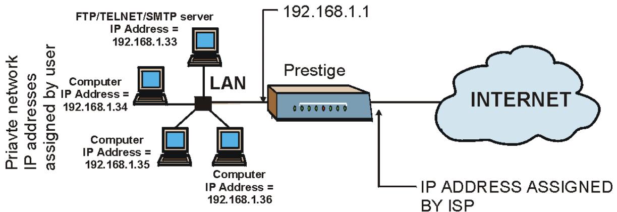
flowchart
graph TD
    A["Internet"] -->|IP ADDRESS ASSIGNED BY ISP| B["Prestige"]
    B --> C["LAN"]
    C --> D["Computer IP Address = 192.168.1.34"]
    C --> E["Computer IP Address = 192.168.1.35"]
    C --> F["Computer IP Address = 192.168.1.36"]
    G["FTP/TELNET/SMTP server"] --> H["IP Address = 192.168.1.33"]
    G --> I["192.168.1.1"]
    style A fill:#cce5ff,stroke:#333
    style B fill:#d4edda,stroke:#333
    style C fill:#fff,stroke:#333
    style D fill:#e6f7ff,stroke:#333
    style E fill:#e6f7ff,stroke:#333
    style F fill:#e6f7ff,stroke:#333
    style G fill:#cce5ff,stroke:#333
Figure 8-3 Multiple Servers Behind NAT Example
8.4 Selecting the NAT Mode
You must create a firewall rule in addition to setting up SUA/NAT, to allow traffic from the WAN to be forwarded through the Prestige.
Click NAT to open the following screen.
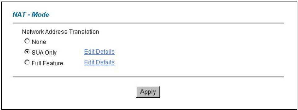
Figure 8-4 NAT Mode
Table 8-4 NAT Mode
| LABEL | DESCRIPTION |
| None | Select this radio button to disable NAT. |
| SUA Only | Select this radio button if you have just one public WAN IP address for your Prestige. The Prestige uses Address Mapping Set 1 in the NAT - Edit SUA NAT Server Set screen. |
| Edit Details | Click this link to go to the NAT - Edit SUA NAT Server Set screen. |
| Full Feature | Select this radio button if you have multiple public WAN IP addresses for your Prestige. |
| Edit Details | Click this link to go to the NAT - Address Mapping Rules screen. |
| Apply | Click Apply to save your configuration. |
8.5 Configuring SUA Server
If you do not assign a Default Server IP Address, then all packets received for ports not specified in this screen will be discarded.
Click NAT, Select SUA Only and click Edit Details to open the following screen. Refer to the firewall chapters for port numbers commonly used for particular services.
NAT · Edit SUA/NAT Server Set
| Start Port No. | End Port No. | IP Address | |
| 1 | All ports | All ports | 0.0.0.0 |
| 2 | 0 | 0 | 0.0.0.0 |
| 3 | 0 | 0 | 0.0.0.0 |
| 4 | 0 | 0 | 0.0.0.0 |
| 5 | 0 | 0 | 0.0.0.0 |
| 6 | 0 | 0 | 0.0.0.0 |
| 7 | 0 | 0 | 0.0.0.0 |
| 8 | 0 | 0 | 0.0.0.0 |
| 9 | 0 | 0 | 0.0.0.0 |
| 10 | 0 | 0 | 0.0.0.0 |
| 11 | 0 | 0 | 0.0.0.0 |
| 12 | 0 | 0 | 0.0.0.0 |

Figure 8-5 Edit SUA/NAT Server Set
The following table describes the fields in this screen.
Table 8-5 Edit SUA/NAT Server Set
| LABEL | DESCRIPTION |
| Start Port No. | Enter a port number in this field.To forward only one port, enter the port number again in the End Port No. field.To forward a series of ports, enter the start port number here and the end port number in the End Port No. field. |
| End Port No. | Enter a port number in this field.To forward only one port, enter the port number again in the Start Port No. field above and then enter it again in this field.To forward a series of ports, enter the last port number in a series that begins with the port number in the Start Port No. field above. |
Table 8-5 Edit SUA/NAT Server Set
| LABEL | DESCRIPTION |
| Server IP Address | Enter your server IP address in this field. |
| Save | Click Save to save your changes back to the Prestige. |
| Cancel | Click Cancel to return to the previous configuration. |
8.6 Configuring Address Mapping
Ordering your rules is important because the Prestige applies the rules in the order that you specify. When a rule matches the current packet, the Prestige takes the corresponding action and the remaining rules are ignored. If there are any empty rules before your new configured rule, your configured rule will be pushed up by that number of empty rules. For example, if you have already configured rules 1 to 6 in your current set and now you configure rule number 9. In the set summary screen, the new rule will be rule 7, not 9. Now if you delete rule 4, rules 5 to 7 will be pushed up by 1 rule, so old rules 5, 6 and 7 become new rules 4, 5 and 6.
To change your Prestige's address mapping settings, click NAT, Select Full Feature and click Edit Details to open the following screen.
| Local Start IP | Local End IP | Global Start IP | Global End IP | Type | |
| Rule 1 | ... | ... | ... | ... | - |
| Rule 2 | ... | ... | ... | ... | - |
| Rule 3 | ... | ... | ... | ... | - |
| Rule 4 | ... | ... | ... | ... | - |
| Rule 5 | ... | ... | ... | ... | - |
| Rule 6 | ... | ... | ... | ... | - |
| Rule 7 | ... | ... | ... | ... | - |
| Rule 8 | ... | ... | ... | ... | - |
| Rule 9 | ... | ... | ... | ... | - |
| Rule 10 | ... | ... | ... | ... | - |
Figure 8-6 Address Mapping Rules
The following table describes the fields in this screen.
Table 8-6 Address Mapping Rules
| LABEL | DESCRIPTION |
| Local Start IP | This is the starting Inside Local IP Address (ILA). Local IP addresses are N/A for Server port mapping. |
| Local End IP | This is the end Inside Local IP Address (ILA). If your rule is for all local IP addresses, then enter 0.0.0.0 as the Local Start IP address and 255.255.255.255 as the Local End IP address. This field is N/A for One-to-one and Server mapping types. |
| Global Start IP | This is the starting Inside Global IP Address (IGA). Enter 0.0.0.0 here if you have a dynamic IP address from your ISP. You can only do this for Many-to-One and Server mapping types. |
| Global End IP | This is the ending Inside Global IP Address (IGA). This field is N/A for One-to-one, Many-to-One and Server mapping types. |
| Type | 1-1: One-to-one mode maps one local IP address to one global IP address. Note that port numbers do not change for the One-to-one NAT mapping type.M-1: Many-to-One mode maps multiple local IP addresses to one global IP address. This is equivalent to SUA (i.e., PAT, port address translation), ZyXEL's Single User Account feature that previous ZyXEL routers supported only.M-M Ov (Overload): Many-to-Many Overload mode maps multiple local IP addresses to shared global IP addresses.MM No (No Overload): Many-to-Many No Overload mode maps each local IP address to unique global IP addresses.Server: This type allows you to specify inside servers of different services behind the NAT to be accessible to the outside world. |
| Back | Click Back to return to the NAT Mode screen. |
8.7 Editing an Address Mapping Rule
To edit an address mapping rule, click the rule's link in the NAT Address Mapping Rules screen to display the screen shown next.
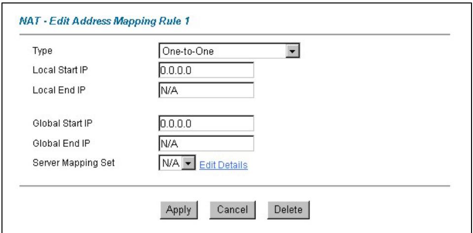
Figure 8-7 Address Mapping Rule Edit
The following table describes the fields in this screen.
Table 8-7 Address Mapping Rule Edit
| LABEL | DESCRIPTION |
| Type | Choose the port mapping type from one of the following.1.One-to-One: One-to-One mode maps one local IP address to one global IP address. Note that port numbers do not change for One-to-one NAT mapping type.2.Many-to-One: Many-to-One mode maps multiple local IP addresses to one global IP address. This is equivalent to SUA (i.e., PAT, port address translation), ZyXEL's Single User Account feature that previous ZyXEL routers supported only.3.Many-to-Many Overload: Many-to-Many Overload mode maps multiple local IP addresses to shared global IP addresses.4.Many-to-Many No Overload: Many-to-Many No Overload mode maps each local IP address to unique global IP addresses.5.Server: This type allows you to specify inside servers of different services behind the NAT to be accessible to the outside world. |
| Local Start IP | This is the starting local IP address (ILA). Local IP addresses areN/AforServerport mapping. |
| Local End IP | This is the end local IP address (ILA). If your rule is for all local IP addresses, then enter 0.0.0.0 as theLocal Start IPaddress and 255.255.255.255 as theLocal End IPaddress.This field isN/AforOne-to-OneandServermapping types. |
| Global Start IP | This is the starting global IP address (IGA). Enter 0.0.0.0 here if you have a dynamic IP address from your ISP. |
| Global End IP | This is the ending global IP address (IGA). This field is N/A for One-to-One, Many-to-One and Server mapping types. |
| Server Mapping Set | Only available when Type is set to Server.Select a number from 1 to 10 from the drop-down menu to choose a server set from the NAT - Address Mapping Rules screen. |
| Apply | Click Apply to save your changes back to the Prestige. |
| Cancel | Click Cancel to return to the previously saved settings. |
| Delete | Click Delete to exit this screen without saving |
Chapter 9
Dynamic DNS Setup
This chapter discusses how to configure your Prestige to use Dynamic DNS.
9.1 Dynamic DNS
Dynamic DNS allows you to update your current dynamic IP address with one or many dynamic DNS services so that anyone can contact you (in NetMeeting, CU-SeeMe, etc.). You can also access your FTP server or Web site on your own computer using a DNS-like address (for instance myhost.dhs.org, where myhost is a name of your choice) that will never change instead of using an IP address that changes each time you reconnect. Your friends or relatives will always be able to call you even if they don't know your IP address.
First of all, you need to have registered a dynamic DNS account with www.dyndns.org. This is for people with a dynamic IP from their ISP or DHCP server that would still like to have a DNS name. The Dynamic DNS service provider will give you a password or key.
9.1.1 DYNDNS Wildcard
Enabling the wildcard feature for your host causes *.yourhost.dyndns.org to be aliased to the same IP address as yourhost.dyndns.org. This feature is useful if you want to be able to use, for example, www.yourhost.dyndns.org and still reach your hostname.
If you have a private WAN IP address, then you cannot use Dynamic DNS.
9.2 Configuring Dynamic DNS
To change your Prestige's DDNS, click Dynamic DNS. The screen appears as shown.
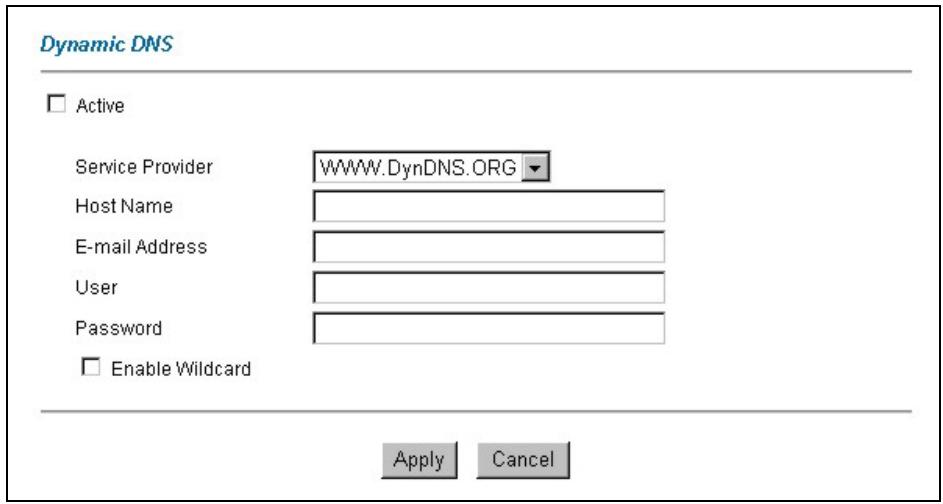
Figure 9-1 DDNS
The following table describes the fields in this screen.
Table 9-1 DDNS
| LABEL | DESCRIPTION |
| Active | Select this check box to use dynamic DNS. |
| Service Provider | Select the name of your Dynamic DNS service provider. |
| Host Names | Type the domain name assigned to your Prestige by your Dynamic DNS provider. |
| E-mail Address | Type your e-mail address. |
| User | Type your user name. |
| Password | Type the password assigned to you. |
| Enable Wildcard | Select the check box to enable DYNDNS Wildcard. |
| Apply | Click Apply to save your changes back to the Prestige. |
| Cancel | Click Cancel to return to the previously saved settings. |
Chapter 10 Time Zone
This screen is not available on all models. Use this screen to configure the Prestige's time and date settings.
10.1 Configuring Time Zone
To change your Prestige's time and date, click Time Zone. The screen appears as shown. Use this screen to configure the Prestige's time based on your local time zone.
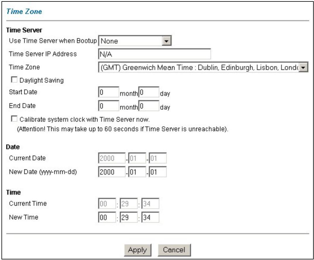
Figure 10-1 Time/Date
The following table describes the fields in this screen.
Table 10-1 Time/Date
| LABEL | DESCRIPTION |
| Time Server | |
| Use Time Server when Bootup | Select the time service protocol that your time server sends when you turn on the Prestige. Not all time servers support all protocols, so you may have to check with your ISP/network administrator or use trial and error to find a protocol that works.The main difference between them is the format.Daytime (RFC 867) format is day/month/year/time zone of the server.Time (RFC 868) format displays a 4-byte integer giving the total number of seconds since 1970/1/1 at 0:0:0.The default, NTP (RFC 1305), is similar to Time (RFC 868).Select None to enter the time and date manually. |
| Time Server IP Address | Enter the IP address of your time server. Check with your ISP/network administrator if you are unsure of this information (the default is tick.stdtime.gov.tw). |
| Time Zone | Choose the time zone of your location. This will set the time difference between your time zone and Greenwich Mean Time (GMT). |
| Daylight Savings | Select this option if you use daylight savings time. Daylight saving is a period from late spring to early fall when many countries set their clocks ahead of normal local time by one hour to give more daytime light in the evening. |
| Start Date | Enter the month and day that your daylight-savings time starts on if you selected Daylight Savings. |
| End Date | Enter the month and day that your daylight-savings time ends on if you selected Daylight Savings. |
| Calibrate system clock with Time Server now | Click this button to have your Prestige use the time server (that you configured above) to set its internal system clock. |
| Date | |
| Current Date | This field displays the date of your Prestige.Each time you reload this page, the Prestige synchronizes the time with the time server. |
| New Date | This field displays the last updated date from the time server.When you select None in the Use Time Server when Bootup field, enter the new date in this field and then click Apply. |
| Time |
Table 10-1 Time/Date
| LABEL | DESCRIPTION |
| Current Time | This field displays the time of your Prestige.Each time you reload this page, the Prestige synchronizes the time with the time server. |
| New Time | This field displays the last updated time from the time server.When you select None in the Use Time Server when Bootup field, enter the new time in this field and then click Apply. |
| Apply | Click Apply to save your changes back to the Prestige. |
| Cancel | Click Cancel to return to the previously saved settings. |
Part IV:
Firewall and Content Filters
This part introduces firewalls in general and the Prestige firewall. It also explains customized services and logs and gives example firewall rules and an overview of content filtering.
Chapter 11 Firewalls
This chapter gives some background information on firewalls and introduces the Prestige firewall.
11.1 Firewall Overview
Originally, the term firewall referred to a construction technique designed to prevent the spread of fire from one room to another. The networking term “firewall” is a system or group of systems that enforces an access-control policy between two networks. It may also be defined as a mechanism used to protect a trusted network from an untrusted network. Of course, firewalls cannot solve every security problem. A firewall is one of the mechanisms used to establish a network security perimeter in support of a network security policy. It should never be the only mechanism or method employed. For a firewall to guard effectively, you must design and deploy it appropriately. This requires integrating the firewall into a broad information-security policy. In addition, specific policies must be implemented within the firewall itself.
11.2 Types of Firewalls
There are three main types of firewalls:
- Packet Filtering Firewalls
- Application-level Firewalls
- Stateful Inspection Firewalls
11.2.1 Packet Filtering Firewalls
Packet filtering firewalls restrict access based on the source/destination computer network address of a packet and the type of application.
11.2.2 Application-level Firewalls
Application-level firewalls restrict access by serving as proxies for external servers. Since they use programs written for specific Internet services, such as HTTP, FTP and telnet, they can evaluate network packets for valid application-specific data. Application-level gateways have a number of general advantages over the default mode of permitting application traffic directly to internal hosts:
i. Information hiding prevents the names of internal systems from being made known via DNS to outside systems, since the application gateway is the only host whose name must be made known to outside systems.
ii. Robust authentication and logging pre-authenticates application traffic before it reaches internal hosts and causes it to be logged more effectively than if it were logged with standard host logging. Filtering rules at the packet filtering router can be less complex than they would be if the router needed to filter application traffic and direct it to a number of specific systems. The router need only allow application traffic destined for the application gateway and reject the rest.
11.2.3 Stateful Inspection Firewalls
Stateful inspection firewalls restrict access by screening data packets against defined access rules. They make access control decisions based on IP address and protocol. They also "inspect" the session data to assure the integrity of the connection and to adapt to dynamic protocols. These firewalls generally provide the best speed and transparency, however, they may lack the granular application level access control or caching that some proxies support. See section 11.5 for more information on Stateful Inspection.
Firewalls, of one type or another, have become an integral part of standard security solutions for enterprises.
11.3 Introduction to ZyXEL's Firewall
The Prestige firewall is a stateful inspection firewall and is designed to protect against Denial of Service attacks when activated (in SMT menu 21.2 or in the web configurator). The Prestige's purpose is to allow a private Local Area Network (LAN) to be securely connected to the Internet. The Prestige can be used to prevent theft, destruction and modification of data, as well as log events, which may be important to the security of your network. The Prestige also has packet filtering capabilities.
The Prestige is installed between the LAN and the Internet. This allows it to act as a secure gateway for all data passing between the Internet and the LAN.
The Prestige has one ISDN port and one Ethernet LAN port, which physically separate the network into two areas.
☐ The ISDN port connects to the Internet.
☐ The LAN (Local Area Network) port attaches to a network of computers, which needs security from the outside world. These computers will have access to Internet services such as e-mail, FTP, and the World Wide Web. However, “inbound access” will not be allowed unless you configure remote management or create a firewall rule to allow a remote host to use a specific service.
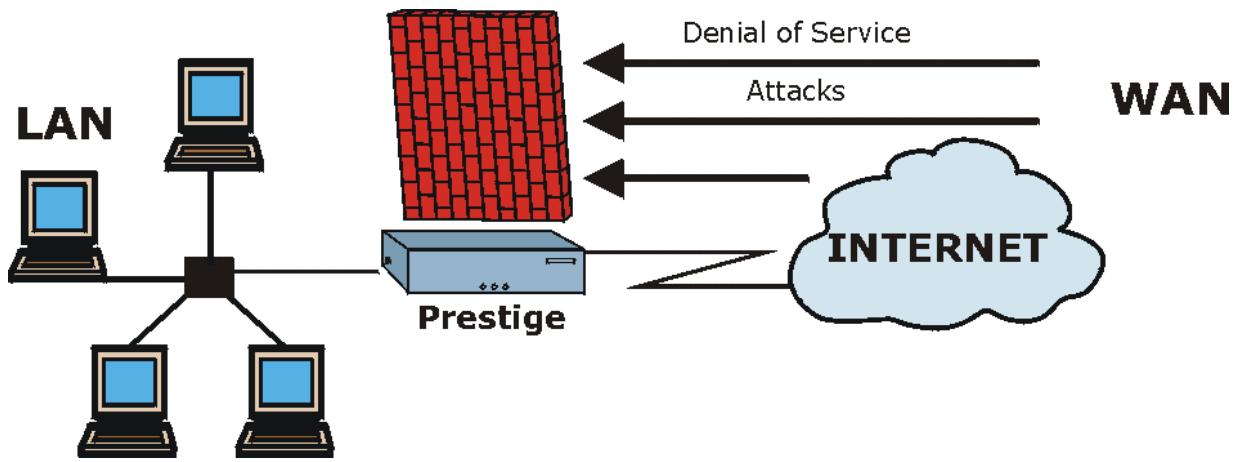
flowchart
graph TD
    A["LAN"] --> B["Central Node"]
    C["Computer"] --> B
    D["Computer"] --> B
    E["Computer"] --> B
    F["Prestige"] --> B
    B --> G["Internet"]
    H["Denial of Service"] --> I["WAN"]
    J["Attacks"] --> I
    K["-->"] --> I
Figure 11-1 Prestige Firewall Application
11.4 Denial of Service
Denials of Service (DoS) attacks are aimed at devices and networks with a connection to the Internet. Their goal is not to steal information, but to disable a device or network so users no longer have access to network resources. The Prestige is pre-configured to automatically detect and thwart all known DoS attacks.
11.4.1 Basics
Computers share information over the Internet using a common language called TCP/IP. TCP/IP, in turn, is a set of application protocols that perform specific functions. An “extension number”, called the "TCP port" or "UDP port" identifies these protocols, such as HTTP (Web), FTP (File Transfer Protocol), POP3 (E-mail), etc. For example, Web traffic by default uses TCP port 80.
When computers communicate on the Internet, they are using the client/server model, where the server "listens" on a specific TCP/UDP port for information requests from remote client computers on the network. For example, a Web server typically listens on port 80. Please note that while a computer may be intended for use over a single port, such as Web on port 80, other ports are also active. If the person configuring or managing the computer is not careful, a hacker could attack it over an unprotected port.
Some of the most common IP ports are:
Table 11-1 Common IP Ports
| 21 | FTP | 53 | DNS |
| 23 | Telnet | 80 | HTTP |
| 25 | SMTP | 110 | POP3 |
11.4.2 Types of DoS Attacks
There are four types of DoS attacks:
- Those that exploit bugs in a TCP/IP implementation.
- Those that exploit weaknesses in the TCP/IP specification.
- Brute-force attacks that flood a network with useless data.
-
IP Spoofing.
-
"Ping of Death" and "Teardrop" attacks exploit bugs in the TCP/IP implementations of various computer and host systems.
1-a Ping of Death uses a "ping" utility to create an IP packet that exceeds the maximum 65,536 bytes of data allowed by the IP specification. The oversize packet is then sent to an unsuspecting system. Systems may crash, hang or reboot.
1-b Teardrop attack exploits weaknesses in the re-assembly of IP packet fragments. As data is transmitted through a network, IP packets are often broken up into smaller chunks. Each fragment looks like the original IP packet except that it contains an offset field that says, for instance, "This fragment is carrying bytes 200 through 400 of the original (non fragmented) IP packet." The Teardrop program creates a series of IP fragments with overlapping offset fields. When these fragments are reassembled at the destination, some systems will crash, hang, or reboot.
- Weaknesses in the TCP/IP specification leave it open to "SYN Flood" and "LAND" attacks. These attacks are executed during the handshake that initiates a communication session between two applications.
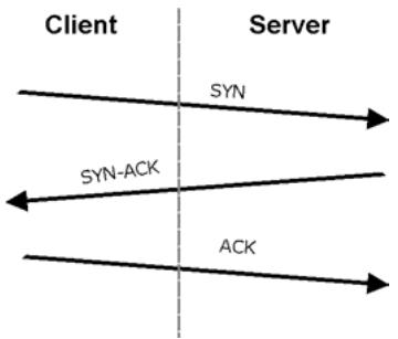
flowchart
graph LR
    A["Client"] --> B["Server"]
    B --> C["SYN"]
    B --> D["SYN-ACK"]
    B --> E["ACK"]
Figure 11-2 Three-Way Handshake
Under normal circumstances, the application that initiates a session sends a SYN (synchronize) packet to the receiving server. The receiver sends back an ACK (acknowledgment) packet and its own SYN, and then the initiator responds with an ACK (acknowledgment). After this handshake, a connection is established.
2-a SYN Attack floods a targeted system with a series of SYN packets. Each packet causes the targeted system to issue a SYN-ACK response. While the targeted system waits for the ACK that follows the SYN-ACK, it queues up all outstanding SYN-ACK responses on what is known as a backlog queue. SYN-ACKs are moved off the queue only when an ACK comes back or when an internal timer (which is set at relatively long intervals) terminates the three-way handshake. Once the queue is full, the system will ignore all incoming SYN requests, making the system unavailable for legitimate users.

flowchart
graph TD
    A["Client"] --> B["SYN"]
    A --> C["SYN"]
    A --> D["SYN"]
    A --> E["SYN"]
    F["Server"] --> G["SYN-ACK"]
    F --> H["SYN-ACK"]
    F --> I["SYN-ACK"]
    F --> J["SYN-ACK"]
Figure 11-3 SYN Flood
2-b In a LAND Attack, hackers flood SYN packets into the network with a spoofed source IP address of the targeted system. This makes it appear as if the host computer sent the packets to itself, making the system unavailable while the target system tries to respond to itself.
- A brute-force attack, such as a "Smurf" attack, targets a feature in the IP specification known as directed or subnet broadcasting, to quickly flood the target network with useless data. A Smurf hacker floods a router with Internet Control Message Protocol (ICMP) echo request packets (pings). Since the destination IP address of each packet is the broadcast address of the network, the router will broadcast the ICMP echo request packet to all hosts on the network. If there are numerous hosts, this will create a large amount of ICMP echo request and response traffic. If a hacker chooses to spoof the source IP address of the ICMP echo request packet, the resulting ICMP traffic will not only clog up the "intermediary" network, but will also congest the network of the spoofed source IP address, known as the "victim" network. This flood of broadcast traffic consumes all available bandwidth, making communications impossible.
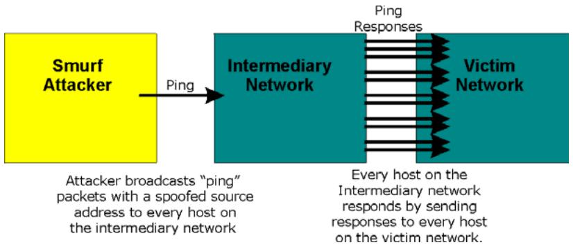
flowchart
graph LR
    A["Smurf Attacker"] -->|Ping| B["Intermediary Network"]
    B --> C["Victim Network"]
    D["Attacker broadcasts "ping" packets with a spoofed source address to every host on the intermediary network"] --> B
    E["Every host on the Intermediary network responds by sending responses to every host on the victim network."] --> C
Figure 11-4 Smurf Attack
☐ ICMP Vulnerability
ICMP is an error-reporting protocol that works in concert with IP. The following ICMP types trigger an alert:
Table 11-2 ICMP Commands That Trigger Alerts
| 5 | REDIRECT |
| 13 | TIMESTAMP_REQUEST |
| 14 | TIMESTAMP_REPLY |
| 17 | ADDRESS_MASK_REQUEST |
| 18 | ADDRESS_MASK_REPLY |
☐ Illegal Commands (NetBIOS and SMTP)
The only legal NetBIOS commands are the following - all others are illegal.
Table 11-3 Legal NetBIOS Commands
| MESSAGE: |
| REQUEST: |
| POSITIVE: |
| NEGATIVE: |
| RETARGET: |
| KEEPALIVE: |
All SMTP commands are illegal except for those displayed in the following tables.
Table 11-4 Legal SMTP Commands
| AUTH | DATA | EHLO | ETRN | EXPN | HELO | HELP | NOOP | |
| QUIT | RCPT | RSET | SAML | SEND | SOML | TURN | VRFY |
Traceroute
Traceroute is a utility used to determine the path a packet takes between two endpoints. Sometimes when a packet filter firewall is configured incorrectly an attacker can traceroute the firewall gaining knowledge of the network topology inside the firewall.
- Often, many DoS attacks also employ a technique known as "IP Spoofing" as part of their attack. IP Spoofing may be used to break into systems, to hide the hacker's identity, or to magnify the effect of the DoS attack. IP Spoofing is a technique used to gain unauthorized access to computers by tricking a router or firewall into thinking that the communications are coming from within the trusted network. To engage in IP spoofing, a hacker must modify the packet headers so that it appears that the packets originate from a trusted host and should be allowed through the router or firewall. The Prestige blocks all IP Spoofing attempts.
11.5 Stateful Inspection
With stateful inspection, fields of the packets are compared to packets that are already known to be trusted. For example, if you access some outside service, the proxy server remembers things about your original request, like the port number and source and destination addresses. This “remembering” is called saving the state. When the outside system responds to your request, the firewall compares the received packets with the saved state to determine if they are allowed in. The Prestige uses stateful packet inspection to protect the private LAN from hackers and vandals on the Internet. By default, the Prestige’s stateful inspection allows all communications to the Internet that originate from the LAN, and blocks all traffic to the LAN that originates from the Internet. In summary, stateful inspection:
☐ Allows all sessions originating from the LAN (local network) to the WAN (Internet).
☐ Denies all sessions originating from the WAN to the LAN.
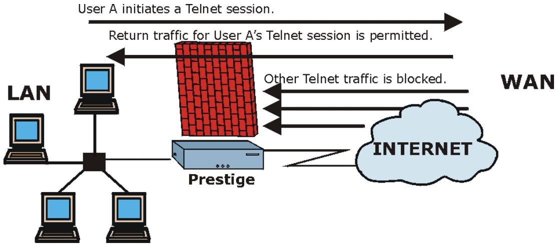
flowchart
graph TD
    A["User A initiates a Telnet session."] --> B["Return traffic for User A's Telnet session is permitted."]
    B --> C["Prestige"]
    C --> D["Other Telnet traffic is blocked."]
    D --> E["INTERNET"]
    F["LAN"] --> G["Computer"]
    G --> H["Computer"]
    H --> I["Computer"]
    I --> J["Computer"]
    J --> K["Computer"]
    K --> L["Computer"]
    L --> M["Computer"]
    M --> N["Computer"]
    N --> O["Computer"]
    O --> P["Computer"]
    P --> Q["Computer"]
    Q --> R["Computer"]
    R --> S["Computer"]
    S --> T["Computer"]
    T --> U["Computer"]
    U --> V["Computer"]
    V --> W["Computer"]
    W --> X["Computer"]
    X --> Y["Computer"]
    Y --> Z["Computer"]
    Z --> AA["Computer"]
    AA --> AB["Computer"]
    AB --> AC["Computer"]
    AC --> AD["Computer"]
    AD --> AE["Computer"]
    AE --> AF["Computer"]
    AF --> AG["Computer"]
    AG --> AH["Computer"]
    AH --> AI["Computer"]
    AI --> AJ["Computer"]
    AJ --> AK["Computer"]
    AK --> AL["Computer"]
    AL --> AM["Computer"]
    AM --> AN["Computer"]
    AN --> AO["Computer"]
    AO --> AP["Computer"]
    AP --> AQ["Computer"]
    AQ --> AR["Computer"]
    AR --> AS["Computer"]
    AS --> AT["Computer"]
    AT --> AU["Computer"]
    AU --> AV["Computer"]
    AV --> AW["Computer"]
    AW --> AX["Computer"]
    AX --> AY["Computer"]
    AY --> AZ["Computer"]
    AZ --> BA["Computer"]
    BA --> BB["Computer"]
    BB --> BC["Computer"]
    BC --> BD["Computer"]
    BD --> BE["Computer"]
    BE --> BF["Computer"]
    BF --> BG["Computer"]
    BG --> BH["Computer"]
    BH --> BI["Computer"]
    BI --> BJ["Computer"]
    BJ --> BK["Computer"]
    BK --> BL["Computer"]
    BL --> BM["Computer"]
    BM --> BN["Computer"]
    BN --> BO["Computer"]
    BO --> BP["Computer"]
    BP --> BQ["Computer"]
    BQ --> BR["Computer"]
    BR --> BS["Computer"]
    BS --> BT["Computer"]
    BT --> BU["Computer"]
    BU --> BV["Computer"]
    BV --> BW["Computer"]
    BW --> BX["Computer"]
    BX --> BY["Computer"]
    BY --> BZ["Computer"]
    BZ --> CA["Computer"]
    CA --> CB["Computer"]
    CB --> CC["Computer"]
    CC --> CD["Computer"]
    CD --> CE["Computer"]
    CE --> CF["Computer"]
    CF --> CG["Computer"]
    CG --> CH["Computer"]
    CH --> CI["Computer"]
    CI --> CJ["Computer"]
    CJ --> CK["Computer"]
    CK --> CR["Computer"]
    CR --> CS["Computer"]
    CS --> CT["Computer"]
    CT --> CU["Computer"]
    CU --> CV["Computer"]
    CV --> CW["Computer"]
    CW --> CX["Computer"]
    CX --> CY["Computer"]
    CY --> CZ["Computer"]
Figure 11-5 Stateful Inspection
The previous figure shows the Prestige's default firewall rules in action as well as demonstrates how stateful inspection works. User A can initiate a Telnet session from within the LAN and responses to this request are allowed. However other Telnet traffic initiated from the WAN is blocked.
11.5.1 Stateful Inspection Process
In this example, the following sequence of events occurs when a TCP packet leaves the LAN network through the firewall's WAN interface. The TCP packet is the first in a session, and the packet's application layer protocol is configured for a firewall rule inspection:
- The packet travels from the firewall's LAN to the WAN.
- The packet is evaluated against the interface's existing outbound access list, and the packet is permitted (a denied packet would simply be dropped at this point).
- The packet is inspected by a firewall rule to determine and record information about the state of the packet's connection. This information is recorded in a new state table entry created for the new connection. If there is not a firewall rule for this packet and it is not an attack, then The default action for packets not matching following rules field (see Figure 13-3) determines the action for this packet.
- Based on the obtained state information, a firewall rule creates a temporary access list entry that is inserted at the beginning of the WAN interface's inbound extended access list. This temporary
access list entry is designed to permit inbound packets of the same connection as the outbound packet just inspected.
- The outbound packet is forwarded out through the interface.
- Later, an inbound packet reaches the interface. This packet is part of the connection previously established with the outbound packet. The inbound packet is evaluated against the inbound access list, and is permitted because of the temporary access list entry previously created.
- The packet is inspected by a firewall rule, and the connection's state table entry is updated as necessary. Based on the updated state information, the inbound extended access list temporary entries might be modified, in order to permit only packets that are valid for the current state of the connection.
- Any additional inbound or outbound packets that belong to the connection are inspected to update the state table entry and to modify the temporary inbound access list entries as required, and are forwarded through the interface.
- When the connection terminates or times out, the connection's state table entry is deleted and the connection's temporary inbound access list entries are deleted.
11.5.2 Stateful Inspection and the Prestige
Additional rules may be defined to extend or override the default rules. For example, a rule may be created which will:
i. Block all traffic of a certain type, such as IRC (Internet Relay Chat), from the LAN to the Internet.
ii. Allow certain types of traffic from the Internet to specific hosts on the LAN.
iii. Allow access to a Web server to everyone but competitors.
iv. Restrict use of certain protocols, such as Telnet, to authorized users on the LAN.
These custom rules work by evaluating the network traffic's Source IP address, Destination IP address, IP protocol type, and comparing these to rules set by the administrator.
The ability to define firewall rules is a very powerful tool. Using custom rules, it is possible to disable all firewall protection or block all access to the Internet. Use extreme caution when creating or deleting firewall rules. Test changes after creating them to make sure they work correctly.
Below is a brief technical description of how these connections are tracked. Connections may either be defined by the upper protocols (for instance, TCP), or by the Prestige itself (as with the "virtual connections" created for UDP and ICMP).
11.5.3 TCP Security
The Prestige uses state information embedded in TCP packets. The first packet of any new connection has its SYN flag set and its ACK flag cleared; these are "initiation" packets. All packets that do not have this flag structure are called "subsequent" packets, since they represent data that occurs later in the TCP stream.
If an initiation packet originates on the WAN, this means that someone is trying to make a connection from the Internet into the LAN. Except in a few special cases (see "Upper Layer Protocols" shown next), these packets are dropped and logged.
If an initiation packet originates on the LAN, this means that someone is trying to make a connection from the LAN to the Internet. Assuming that this is an acceptable part of the security policy (as is the case with the default policy), the connection will be allowed. A cache entry is added which includes connection information such as IP addresses, TCP ports, sequence numbers, etc.
When the Prestige receives any subsequent packet (from the Internet or from the LAN), its connection information is extracted and checked against the cache. A packet is only allowed to pass through if it corresponds to a valid connection (that is, if it is a response to a connection which originated on the LAN).
11.5.4 UDP/ICMP Security
UDP and ICMP do not themselves contain any connection information (such as sequence numbers). However, at the very minimum, they contain an IP address pair (source and destination). UDP also contains port pairs, and ICMP has type and code information. All of this data can be analyzed in order to build "virtual connections" in the cache.
For instance, any UDP packet that originates on the LAN will create a cache entry. Its IP address and port pairs will be stored. For a short period of time, UDP packets from the WAN that have matching IP and UDP information will be allowed back in through the firewall.
A similar situation exists for ICMP, except that the Prestige is even more restrictive. Specifically, only outgoing echoes will allow incoming echo replies, outgoing address mask requests will allow incoming address mask replies, and outgoing timestamp requests will allow incoming timestamp replies. No other ICMP packets are allowed in through the firewall, simply because they are too dangerous and contain too little tracking information. For instance, ICMP redirect packets are never allowed in, since they could be used to reroute traffic through attacking machines.
11.5.5 Upper Layer Protocols
Some higher layer protocols (such as FTP and RealAudio) utilize multiple network connections simultaneously. In general terms, they usually have a "control connection" which is used for sending commands between endpoints, and then "data connections" which are used for transmitting bulk information.
Consider the FTP protocol. A user on the LAN opens a control connection to a server on the Internet and requests a file. At this point, the remote server will open a data connection from the Internet. For FTP to
work properly, this connection must be allowed to pass through even though a connection from the Internet would normally be rejected.
In order to achieve this, the Prestige inspects the application-level FTP data. Specifically, it searches for outgoing "PORT" commands, and when it sees these, it adds a cache entry for the anticipated data connection. This can be done safely, since the PORT command contains address and port information, which can be used to uniquely identify the connection.
Any protocol that operates in this way must be supported on a case-by-case basis. You can use the web configurator's Custom Ports feature to do this.
11.6 Guidelines For Enhancing Security With Your Firewall
- Change the default password via SMT or web configurator.
- Think about access control before you connect a console port to the network in any way, including attaching a modem to the port. Be aware that a break on the console port might give unauthorized individuals total control of the firewall, even with access control configured.
- Limit who can telnet into your router.
- Don't enable any local service (such as SNMP or NTP) that you don't use. Any enabled service could present a potential security risk. A determined hacker might be able to find creative ways to misuse the enabled services to access the firewall or the network.
- For local services that are enabled, protect against misuse. Protect by configuring the services to communicate only with specific peers, and protect by configuring rules to block packets for the services at specific interfaces.
- Protect against IP spoofing by making sure the firewall is active.
- Keep the firewall in a secured (locked) room.
11.6.1 Security In General
You can never be too careful! Factors outside your firewall, filtering or NAT can cause security breaches. Below are some generalizations about what you can do to minimize them.
-
Encourage your company or organization to develop a comprehensive security plan. Good network administration takes into account what hackers can do and prepares against attacks. The best defense against hackers and crackers is information. Educate all employees about the importance of security and how to minimize risk. Produce lists like this one!
-
DSL or cable modem connections are “always-on” connections and are particularly vulnerable because they provide more opportunities for hackers to crack your system. Turn your computer off when not in use.
-
Never give out a password or any sensitive information to an unsolicited telephone call or e-mail.
- Never e-mail sensitive information such as passwords, credit card information, etc., without encrypting the information first.
- Never submit sensitive information via a web page unless the web site uses secure connections. You can identify a secure connection by looking for a small “key” icon on the bottom of your browser (Internet Explorer 3.02 or better or Netscape 3.0 or better). If a web site uses a secure connection, it is safe to submit information. Secure web transactions are quite difficult to crack.
- Never reveal your IP address or other system networking information to people outside your company. Be careful of files e-mailed to you from strangers. One common way of getting BackOrifice on a system is to include it as a Trojan horse with other files.
- Change your passwords regularly. Also, use passwords that are not easy to figure out. The most difficult passwords to crack are those with upper and lower case letters, numbers and a symbol such as % or #.
- Upgrade your software regularly. Many older versions of software, especially web browsers, have well known security deficiencies. When you upgrade to the latest versions, you get the latest patches and fixes.
- If you use “chat rooms” or IRC sessions, be careful with any information you reveal to strangers.
- If your system starts exhibiting odd behavior, contact your ISP. Some hackers will set off hacks that cause your system to slowly become unstable or unusable.
- Always shred confidential information, particularly about your computer, before throwing it away. Some hackers dig through the trash of companies or individuals for information that might help them in an attack.
11.7 Packet Filtering Vs Firewall
Below are some comparisons between the Prestige's filtering and firewall functions.
11.7.1 Packet Filtering:
- The router filters packets as they pass through the router's interface according to the filter rules you designed.
☐ Packet filtering is a powerful tool, yet can be complex to configure and maintain, especially if you need a chain of rules to filter a service.
☐ Packet filtering only checks the header portion of an IP packet.
When To Use Filtering
-
To block/allow LAN packets by their MAC addresses.
-
To block/allow special IP packets which are neither TCP nor UDP, nor ICMP packets.
-
To block/allow both inbound (WAN to LAN) and outbound (LAN to WAN) traffic between the specific inside host/network "A" and outside host/network "B". If the filter blocks the traffic from A to B, it also blocks the traffic from B to A. Filters can not distinguish traffic originating from an inside host or an outside host by IP address.
-
To block/allow IP trace route.
11.7.2 Firewall
☐ The firewall inspects packet contents as well as their source and destination addresses. Firewalls of this type employ an inspection module, applicable to all protocols, that understands data in the packet is intended for other layers, from the network layer (IP headers) up to the application layer.
☐ The firewall performs stateful inspection. It takes into account the state of connections it handles so that, for example, a legitimate incoming packet can be matched with the outbound request for that packet and allowed in. Conversely, an incoming packet masquerading as a response to a nonexistent outbound request can be blocked.
☐ The firewall uses session filtering, i.e., smart rules, that enhance the filtering process and control the network session rather than control individual packets in a session.
☐ The firewall provides e-mail service to notify you of routine reports and when alerts occur.
When To Use The Firewall
- To prevent DoS attacks and prevent hackers cracking your network.
- A range of source and destination IP addresses as well as port numbers can be specified within one firewall rule making the firewall a better choice when complex rules are required.
- To selectively block/allow inbound or outbound traffic between inside host/networks and outside host/networks. Remember that filters can not distinguish traffic originating from an inside host or an outside host by IP address.
- The firewall performs better than filtering if you need to check many rules.
- Use the firewall if you need routine e-mail reports about your system or need to be alerted when attacks occur.
- The firewall can block specific URL traffic that might occur in the future. The URL can be saved in an Access Control List (ACL) database.
Chapter 12
Firewall Configuration
This chapter shows you how to enable and configure the Prestige firewall.
12.1 Remote Management and the Firewall
When remote management is configured to allow management (see the Remote Management chapter) and the firewall is enabled:
- The firewall blocks remote management from the WAN unless you configure a firewall rule to allow it.
- The firewall allows remote management from the LAN.
12.2 Enabling the Firewall
Click Advanced Setup, Firewall, and then Config to display the following screen. Select the Firewall Enabled check box and click Apply to enable (or activate) the firewall.
Firewall · Configuration · Config
□ Firewall Enabled
The firewall protects against Denial of Service (DOS) attacks when it is active. The default Policy sets
- allow all sessions originating from the Local Network to the Internet and
- deny all sessions originating from the Internet to the Local Network
You may define additional Policy rules or modify existing ones but please exercise extreme caution in doing so
- Local Network to Internet Set
- Internet to Local Network Set
CAUTION: If Firewall Enabled is not checked, all the existing firewall security policies and firewall functions will be disabled.
Back
Apply
Cancel
Figure 12-1 Enabling the Firewall
12.3 Attack Alert
Attack alerts are real-time reports of DoS attacks. In the Attack Alert screen, shown later, you may choose to generate an alert whenever an attack is detected. For DoS attacks, the Prestige uses thresholds to determine when to drop sessions that do not become fully established. These thresholds apply globally to all sessions.
You can use the default threshold values, or you can change them to values more suitable to your security requirements.
12.3.1 Alerts
Alerts are reports on events, such as attacks, that you may want to know about right away. You can choose to generate an alert when an attack is detected in the Attack Alert screen (Figure 12-2 - select the Generate alert when attack detected checkbox) or when a rule is matched in the Rule Config screen (see Figure 13-4). When an event generates an alert, a message can be immediately sent to an e-mail account that you specify in the Log Settings screen (see the chapter on logs).
12.3.2 Threshold Values
Tune these parameters when something is not working and after you have checked the firewall counters. These default values should work fine for most small offices. Factors influencing choices for threshold values are:
- The maximum number of opened sessions.
- The minimum capacity of server backlog in your LAN network.
- The CPU power of servers in your LAN network.
- Network bandwidth.
- Type of traffic for certain servers.
If your network is slower than average for any of these factors (especially if you have servers that are slow or handle many tasks and are often busy), then the default values should be reduced.
You should make any changes to the threshold values before you continue configuring firewall rules.
12.3.3 Half-Open Sessions
An unusually high number of half-open sessions (either an absolute number or measured as the arrival rate) could indicate that a Denial of Service attack is occurring. For TCP, "half-open" means that the session has not reached the established state-the TCP three-way handshake has not yet been completed (see Figure 11-2). For UDP, "half-open" means that the firewall has detected no return traffic.
The Prestige measures both the total number of existing half-open sessions and the rate of session establishment attempts. Both TCP and UDP half-open sessions are counted in the total number and rate measurements. Measurements are made once a minute.
When the number of existing half-open sessions rises above a threshold (max-incomplete high), the Prestige starts deleting half-open sessions as required to accommodate new connection requests. The Prestige continues to delete half-open requests as necessary, until the number of existing half-open sessions drops below another threshold (max-incomplete low).
When the rate of new connection attempts rises above a threshold (one-minute high), the Prestige starts deleting half-open sessions as required to accommodate new connection requests. The Prestige continues to delete half-open sessions as necessary, until the rate of new connection attempts drops below another threshold (one-minute low). The rate is the number of new attempts detected in the last one-minute sample period.
TCP Maximum Incomplete and Blocking Time
An unusually high number of half-open sessions with the same destination host address could indicate that a Denial of Service attack is being launched against the host.
Whenever the number of half-open sessions with the same destination host address rises above a threshold (TCP Maximum Incomplete), the Prestige starts deleting half-open sessions according to one of the following methods:
- If the Blocking Time timeout is 0 (the default), then the Prestige deletes the oldest existing half-open session for the host for every new connection request to the host. This ensures that the number of half-open sessions to a given host will never exceed the threshold.
- If the Blocking Time timeout is greater than 0, then the Prestige blocks all new connection requests to the host giving the server time to handle the present connections. The Prestige continues to block all new connection requests until the Blocking Time expires.
The Prestige also sends alerts whenever TCP Maximum Incomplete is exceeded. The global values specified for the threshold and timeout apply to all TCP connections. Click Advanced Setup, Firewall, and Alert to bring up the next screen.
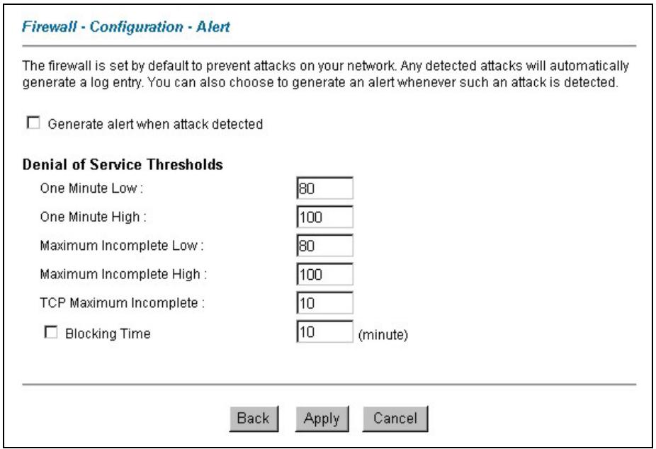
Figure 12-2 Attack Alert
The following table describes the fields in this screen.
Table 12-1 Attack Alert
| LABEL | DESCRIPTION |
| Generate alert when attack detected | Select this check box to generate an alert whenever an attack is detected. |
| Denial of Services Thresholds | |
| One Minute Low | This is the rate of new half-open sessions that causes the firewall to stop deleting half-open sessions.The Prestige continues to delete half-open sessions as necessary, until the rate of new connection attempts drops below this number. "80" is the default. |
| One Minute High | This is the rate of new half-open sessions that causes the firewall to start deleting half-open sessions. The default is "100". When the rate of new connection attempts rises above this number, the Prestige deletes half-open sessions as required to accommodate new connection attempts. The Prestige stops deleting half-open sessions when the number is less than the One Minute Low. |
Table 12-1 Attack Alert
| LABEL | DESCRIPTION |
| Maximum Incomplete Low | This is the number of existing half-open sessions (default "80") that causes the firewall to stop deleting half-open sessions.The Prestige continues to delete half-open requests as necessary, until the number of existing half-open sessions drops below this number. |
| Maximum Incomplete High | This is the number of existing half-open sessions (default "100") that causes the firewall to start deleting half-open sessions. When the number of existing half-open sessions rises above this number, the Prestige deletes half-open sessions as required to accommodate new connection requests. The Prestige stops deleting half-open sessions when the number is less than theMax Incomplete Low.Do not setMaximum Incomplete Highto lower than the current Max Incomplete Lownumber. |
| TCP Maximum Incomplete | This is the number of existing half-open TCP sessions (default "10") with the same destination host IP address that causes the firewall to start dropping half-open sessions to that same destination host IP address. Enter a number between 1 and 256.As a general rule, you should choose a smaller number for a smaller network, a slower system or limited bandwidth. |
| Blocking Time | WhenTCP Maximum Incompleteis reached you can choose if the next session should be allowed or blocked. If you selectBlocking Time, any new sessions will be blocked for the length of time you specify in the next field (min) and all old incomplete sessions will be cleared during this period.If you want strong security, it is better to block the traffic for a short time, as it will give the server some time to digest the loading. |
| (min) | Type the length ofBlocking Timein minutes (1-256). The default is "0". |
| Back | ClickBackto return to the previous screen. |
| Apply | ClickApplyto save your customized settings and exit this screen. |
| Cancel | ClickCancelto return to the previously saved settings. |
Chapter 13
Creating Custom Rules
This chapter contains instructions for defining both Local Network and Internet rules.
13.1 Rules Overview
Firewall rules are subdivided into “Local Network” and “Internet”. By default, the Prestige’s stateful packet inspection allows all communications to the Internet that originate from the local network, and blocks all traffic to the LAN that originates from the Internet. You may define additional rules and sets or modify existing ones but please exercise extreme caution in doing so.
You might inadvertently introduce security risks to the firewall and to the protected network, if you try to configure rules without a good understanding of how rules work. Make sure you test your rules after you configure them.
For example, you may create rules to:
◆ Block certain types of traffic, such as IRC (Internet Relay Chat), from the LAN to the Internet.
Allow certain types of traffic, such as Lotus Notes database synchronization, from specific hosts on the Internet to specific hosts on the LAN.
◆ Allow everyone except your competitors to access a Web server.
◆ Restrict use of certain protocols, such as Telnet, to authorized users on the LAN.
These custom rules work by comparing network traffic's Source IP address, Destination IP address, IP protocol type to rules set by the administrator. Your customized rules take precedence, and may override the Prestige's default rules.
13.2 Rule Logic Overview
Study these points carefully before configuring rules.
13.2.1 Rule Checklist
- State the intent of the rule. For example, “This restricts all IRC access from the LAN to the Internet.” Or, “This allows a remote Lotus Notes server to synchronize over the Internet to an inside Notes server.”
-
Is the intent of the rule to forward or block traffic?
-
What is the direction connection: from the LAN to the Internet, or from the Internet to the LAN?
- What IP services will be affected?
- What computers on the LAN are to be affected (if any)?
- What computers on the Internet will be affected? The more specific, the better. For example, if traffic is being allowed from the Internet to the LAN, it is better to allow only certain machines on the Internet to access the LAN.
13.2.2 Security Ramifications
Once the logic of the rule has been defined, it is critical to consider the security ramifications created by the rule:
- Does this rule stop LAN users from accessing critical resources on the Internet? For example, if IRC is blocked, are there users that require this service?
- Is it possible to modify the rule to be more specific? For example, if IRC is blocked for all users, will a rule that blocks just certain users be more effective?
- Does a rule that allows Internet users access to resources on the LAN create a security vulnerability? For example, if FTP ports (TCP 20, 21) are allowed from the Internet to the LAN, Internet users may be able to connect to computers with running FTP servers.
- Does this rule conflict with any existing rules?
Once these questions have been answered, adding rules is simply a matter of plugging the information into the correct fields in the Rules screen in the web configurator.
13.2.3 Key Fields For Configuring Rules
Action
Should the action be to Block or Forward?
"Block" means the firewall silently discards the packet.
Service
Select the service from the Service scrolling list box. If the service is not listed, it is necessary to first define it. See section 13.6 for more information on predefined services.
Source Address
What is the connection's source address; is it on the LAN or WAN? Is it a single IP, a range of IPs or a subnet?
Destination Address
What is the connection's destination address; is it on the LAN or WAN? Is it a single IP, a range of IPs or a subnet?
13.3 Connection Direction
This section talks about configuring firewall rules for connections going from LAN to WAN and WAN to LAN in your firewall.
13.3.1 LAN to WAN Rules
The default rule for LAN to WAN traffic is that all users on the LAN are allowed non-restricted access to the WAN. When you configure Policy -> LAN to WAN -> Rules, you in essence want to limit some or all users from accessing certain services on the WAN. See the following figure.
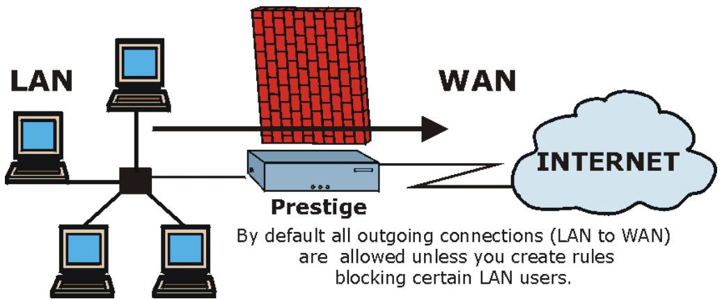
flowchart
graph TD
    A["LAN"] --> B["Prestige"]
    C["Computer"] --> B
    D["Computer"] --> B
    E["Computer"] --> B
    B --> F["WAN"]
    F --> G["INTERNET"]
    style B fill:#f9f9f9,stroke:#333
    note bottom
        By default all outgoing connections (LAN to WAN)
        are allowed unless you create rules blocking certain LAN users.
    end
Figure 13-1 LAN to WAN Traffic
13.3.2 WAN to LAN Rules
The default rule for WAN to LAN traffic blocks all incoming connections (WAN to LAN). If you wish to allow certain WAN users to have access to your LAN, you will need to create custom rules to allow it.
See the following figure.
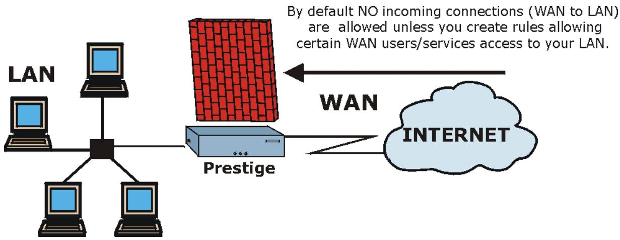
flowchart
graph TD
    A["LAN"] --> B["Central Node"]
    B --> C["Prestige"]
    C --> D["INTERNET"]
    D -->|WAN| E["Internet"]
    style A fill:#f9f,stroke:#333
    style B fill:#ccf,stroke:#333
    style C fill:#cfc,stroke:#333
    style D fill:#fcc,stroke:#333
    note1["By default NO incoming connections (WAN to LAN) are allowed unless you create rules allowing certain WAN users/services access to your LAN."] --> C
Figure 13-2 WAN to LAN Traffic
13.4 Logs
A log is a detailed record that you create for packets that either match a rule, don't match a rule or both when you are creating/editing a firewall rule (see Figure 13-4). You can also choose not to create a log for a rule in this screen. An attack automatically generates a log. Logs can be sent to an e-mail account or syslog server that you specify in the Log Settings screen (see the chapter on logs).
13.5 Rule Summary
The fields in the Rule Summary screens are the same for Local Network and Internet, so the discussion below refers to both.
Click on Firewall, then Rule Summary to bring up the following screen. This screen is a summary of the existing rules. Note the order in which the rules are listed.
The ordering of your rules is very important as rules are applied in turn.
Firewall · LAN to WAN · Rule Summary
The default action for packets not matching following rules: Forward
Default Permit Log
| No. | Source IP | Destination IP | Service | Action | Log |
| 1 | |||||
| 2 | |||||
| 3 | |||||
| 4 | |||||
| 5 | |||||
| 6 | |||||
| 7 | |||||
| 8 | |||||
| 9 | |||||
| 10 |


Figure 13-3 Firewall Rules Summary: First Screen
The following table describes the fields in this screen.
Table 13-1 Firewall Rules Summary: First Screen
| LABEL | DESCRIPTION |
| The default action for packets not matching following rules | Use the drop-down list box to select whether to Block (silently discard) or Forward (allow the passage of) packets that do not match the following rules. |
| Default Permit Log | Select this check box to log all matched rules in the default set. |
| The following fields summarize the rules you have created. Note that these fields are read only. Click the tab at the top of the box to order the rules according to that tab. | |
Table 13-1 Firewall Rules Summary: First Screen
| LABEL | DESCRIPTION |
| No. | This is your firewall rule number. The ordering of your rules is important as rules are applied in turn. TheMovefield below allows you to reorder your rules. Click a rule's number to edit the rule. |
| Source IP | This is the source address of the packet. Please note that a blank source or destination address is equivalent toAny. |
| Destination IP | This is the destination address of the packet. Please note that a blank source or destination address is equivalent toAny. |
| Service | This is the service to which the rule applies. SeeTable 13-2 for more information. |
| Action | This is the specified action for that rule, whether toBlock (discard) orForward (allow the passage of) packets. |
| Log | This field shows you if a log is created for packets that match the rule (Match), don't match the rule (Not Match), both (Both) or no log is created (None). |
| Rules Reorder | You may reorder your rules using this function. Use the drop-sown list box to select the number of the rule you want to move. The ordering of your rules is important as rules are applied in turn. |
| To Rule Number | Use the drop-sown list box to select to where you want to move the rule. |
| Move | ClickMoveto move the rule. |
| Back | ClickBackto return to the previous screen. |
| Apply | ClickApplyto save your changes back to the Prestige. |
| Cancel | ClickCancelto return to the previously saved settings. |
13.6 Predefined Services
The Available Services list box in the Edit Rule screen (see Figure 13-4) displays all predefined services that the Prestige already supports. Next to the name of the service, two fields appear in brackets. The first field indicates the IP protocol type (TCP, UDP, or ICMP). The second field indicates the IP port number that defines the service. (Note that there may be more than one IP protocol type. For example, look at the default configuration labeled “(DNS)”. (UDP/TCP:53) means UDP port 53 and TCP port 53. Up to 128 entries are supported. Custom services may also be configured using the Custom Ports function discussed later.
Table 13-2 Predefined Services
| SERVICE | DESCRIPTION |
| AIM(TCP:5190) | AOL's Internet Messenger service, used as a listening port by ICQ. |
| BGP(TCP:179) | Border Gateway Protocol. |
| BOOTP_CLIENT(UDP:68) | DHCP Client. |
| BOOTP_SERVER(UDP:67) | DHCP Server. |
| CU-SEEME(TCP/UDP:7648, 24032) | A popular videoconferencing solution from White Pines Software. |
| DNS(UDP/TCP:53) | Domain Name Server, a service that matches web names (e.g. www.zyxel.com) to IP numbers. |
| FINGER(TCP:79) | Finger is a UNIX or Internet related command that can be used to find out if a user is logged on. |
| FTP(TCP:20.21) | File Transfer Program, a program to enable fast transfer of files, including large files that may not be possible by e-mail. |
| H.323(TCP:1720) | Net Meeting uses this protocol. |
| HTTP(TCP:80) | Hyper Text Transfer Protocol - a client/server protocol for the world wide web. |
| HTTPS | HTTPS is a secured http session often used in e-commerce. |
| ICQ(UDP:4000) | This is a popular Internet chat program. |
| IKE(UDP:500) | The Internet Key Exchange algorithm is used for key distribution and management. |
| IPSEC_TUNNEL(ESP:0) | The IPSEC ESP (Encapsulation Security Protocol) tunneling protocol uses this service. |
| IRC(TCP/UDP:6667) | This is another popular Internet chat program. |
| MSN Messenger(TCP:1863) | Microsoft Networks' messenger service uses this protocol. |
| MULTICAST(IGMP:0) | Internet Group Multicast Protocol is used when sending packets to a specific group of hosts. |
| NEWS(TCP:144) | A protocol for news groups. |
| NFS(UDP:2049) | Network File System - NFS is a client/server distributed file service that provides transparent file-sharing for network environments. |
Table 13-2 Predefined Services
| SERVICE | DESCRIPTION |
| NNTP(TCP:119) | Network News Transport Protocol is the delivery mechanism for the USENET newsgroup service. |
| PING(ICMP:0) | Packet INternet Groper is a protocol that sends out ICMP echo requests to test whether or not a remote host is reachable. |
| POP3(TCP:110) | Post Office Protocol version 3 lets a client computer get e-mail from a POP3 server through a temporary connection (TCP/IP or other). |
| PPTP(TCP:1723) | Point-to-Point Tunneling Protocol enables secure transfer of data over public networks. This is the control channel. |
| PPTP_TUNNEL(GRE:0) | Point-to-Point Tunneling Protocol enables secure transfer of data over public networks. This is the data channel. |
| RCMD(TCP:512) | Remote Command Service. |
| REAL_AUDIO(TCP:7070) | A streaming audio service that enables real time sound over the web. |
| REXEC(TCP:514) | Remote Execution Daemon. |
| RLOGIN(TCP:513) | Remote Login. |
| RTLNET(TCP:107) | Remote Telnet. |
| RTSP(TCP/UDP:554) | The Real Time Streaming (media control) Protocol (RTSP) is a remote control for multimedia on the Internet. |
| SFTP(TCP:115) | Simple File Transfer Protocol. |
| SMTP(TCP:25) | Simple Mail Transfer Protocol is the message-exchange standard for the Internet. SMTP enables you to move messages from one e-mail server to another. |
| SNMP(TCP/UDP:161) | Simple Network Management Program. |
| SNMP-TRAPS(TCP/UDP:162) | Traps for use with the SNMP (RFC:1215). |
| SQL-NET(TCP:1521) | Structured Query Language is an interface to access data on many different types of database systems, including mainframes, midrange systems, UNIX systems and network servers. |
| SSH(TCP/UDP:22) | Secure Shell Remote Login Program. |
| STRM WORKS(UDP:1558) | Stream Works Protocol. |
Table 13-2 Predefined Services
| SERVICE | DESCRIPTION |
| TACACS(UDP:49) | Login Host Protocol used for (Terminal Access Controller Access Control System). |
| TELNET(TCP:23) | Telnet is the login and terminal emulation protocol common on the Internet and in UNIX environments. It operates over TCP/IP networks. Its primary function is to allow users to log into remote host systems. |
| TFTP(UDP:69) | Trivial File Transfer Protocol is an Internet file transfer protocol similar to FTP, but uses the UDP (User Datagram Protocol) rather than TCP (Transmission Control Protocol). |
| VDOLIVE(TCP:7000) | Another videoconferencing solution. |
13.7 Creating/Editing Firewall Rules
To create a new rule, click a number (No.) in the last screen shown to display the following screen.
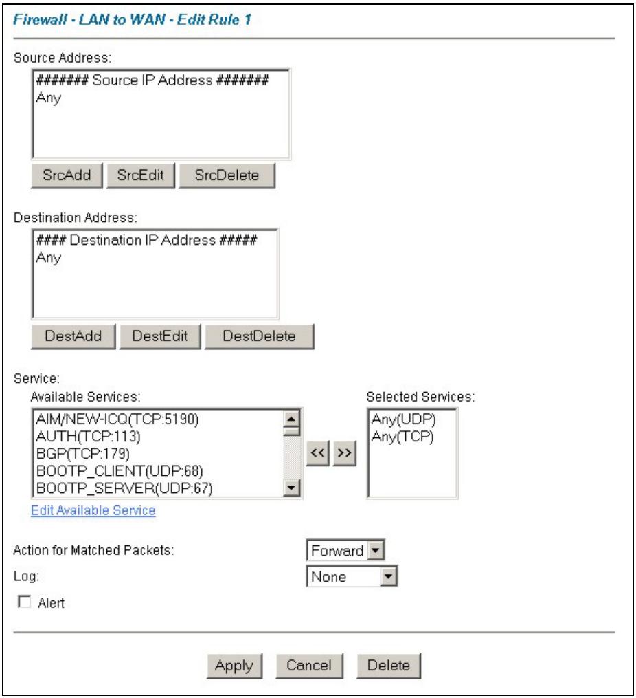
Figure 13-4 Creating/Editing A Firewall Rule
The following table describes the fields in this screen.
Table 13-3 Creating/Editing A Firewall Rule
| LABEL | DESCRIPTION |
| Source Address | Click SrcAdd to add a new address, SrcEdit to edit an existing one or SrcDelete to delete one. |
Table 13-3 Creating/Editing A Firewall Rule
| LABEL | DESCRIPTION |
| Destination Address | Click DestAdd to add a new address, DestEdit to edit an existing one or DestDelete to delete one. |
| Services | Select a service in the Available Services box on the left, then click >> to select. The selected service shows up on the Selected Services box on the right. To remove a service, click on it in the Selected Services box on the right, then click <<. |
| Edit Available Service | Click this button to go to the Customized Services screen.Refer to the Chapter 14 for more information. |
| Action for Matched Packets | Use the drop down list box to select whether to Block (silently discard) or Forward (allow the passage of) packets that match this rule. |
| Log | This field determines if a log is created for packets that match the rule (Match), don't match the rule (Not Match), match either rule (Both) or no log is created (None). |
| Alert | Select the Alert check box to determine that this rule generates an alert when the rule is matched. |
| Apply | Click Apply to save your changes back to the Prestige. |
| Cancel | Click Cancel to exit this screen without saving. |
| Delete | Click Delete to remove the current rule. |
13.7.1 Source and Destination Addresses
To add a new source or destination address, click SrcAdd or DestAdd from the previous screen. To edit an existing source or destination address, select it from the box and click SrcEdit or DestEdit from the previous screen. Either action displays the following screen.
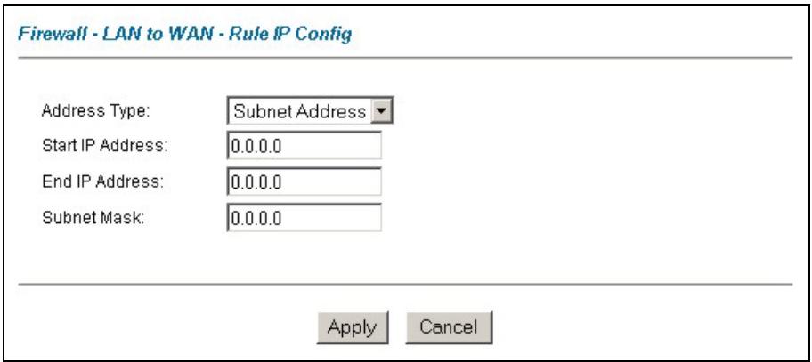
Figure 13-5 Adding/Editing Source and Destination Addresses
The following table describes the fields in this screen.
Table 13-4 Adding/Editing Source and Destination Addresses
| LABEL | DESCRIPTION |
| Address Type | Do you want your rule to apply to packets with a particular (single) IP address, a range of IP addresses (e.g., 192.168.1.10 to 192.169.1.50), a subnet or any IP address? Select an option from the drop-down list box that includes: Single Address, Range Address, Subnet Address and Any Address. |
| Start IP Address | Type the single IP address or the starting IP address in a range here. |
| End IP Address | Type the ending IP address in a range here. |
| Subnet Mask | Type the Subnet Mask here, if applicable. |
| Apply | Click Apply to save your changes back to the Prestige. |
| Cancel | Click Cancel to return to the previously saved settings. |
13.8 Timeout
The fields in the Timeout screens are the same for Local and Internet networks, so the discussion below refers to both.
13.8.1 Factors Influencing Choices for Timeout Values
The factors influencing choices for timeout values are the same as the factors influencing choices for threshold values – see section 12.3.2. Click Timeout for either Local Network or Internet.
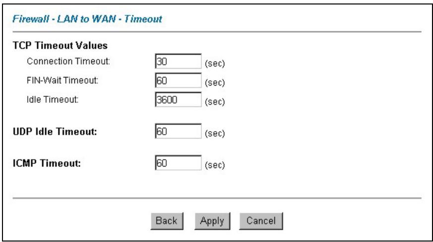
Figure 13-6 Timeout
The following table describes the fields in this screen.
Table 13-5 Timeout
| LABEL | DESCRIPTION |
| TCP Timeout Values | |
| Connection Timeout | Type the number of seconds (default 30) for the Prestige to wait for a TCP session to reach the established state before dropping the session. |
| FIN-Wait Timeout | Type the number of seconds (default 60) for a TCP session to remain open after the firewall detects a FIN-exchange (indicating the end of the TCP session). |
| Idle Timeout | Type the number of seconds (default 3600) for an inactive TCP connection to remain open before the Prestige considers the connection closed. |
| UDP Idle Timeout | Type the number of seconds (default 60) for an inactive UDP connection to remain open before the Prestige considers the connection closed. |
| ICMP Timeout | Type the number of seconds (default 60) for an ICMP session to wait for the ICMP response. |
Table 13-5 Timeout
| LABEL | DESCRIPTION |
| Back | Click Back to return to the previous screen. |
| Apply | Click Apply to save your customized settings and exit this screen. |
| Cancel | Click Cancel to return to the previous configuration. |
Chapter 14
Customized Services
This chapter covers creating, viewing and editing custom services.
14.1 Introduction to Customized Services
Configure customized services and port numbers not predefined by the Prestige (see Figure 13-4). For a comprehensive list of port numbers and services, visit the IANA (Internet Assigned Number Authority) website. For further information on these services, please read section 13.6. To configure a custom service, click Edit Available Service in an edit rule screen to bring up the following screen.
Firewall - Customized Services
| No. | Name | Protocol | Port |
| 1 | |||
| 2 | |||
| 3 | |||
| 4 | |||
| 5 | |||
| 6 | |||
| 7 | |||
| 8 | |||
| 9 | |||
| 10 |
Back
Figure 14-1 Customized Services
The next table describes the fields in this screen.
Table 14-1 Customized Services
| LABEL | DESCRIPTION |
| Customized Services | |
| No. | This is the number of your customized port. Click a rule's number of a service to go to the Firewall Customized Services Config screen to configure or edit a customized service. |
| Name | This is the name of your customized service. |
| Protocol | This shows the IP protocol (TCP, UDP or Both) that defines your customized service. |
| Port | This is the port number or range that defines your customized service. |
| Back | Click Back to return the Firewall Edit Rule screen. |
14.2 Creating/Editing A Customized Service
Click a rule number in the previous screen to create a new custom port or edit an existing one. This action displays the following screen.
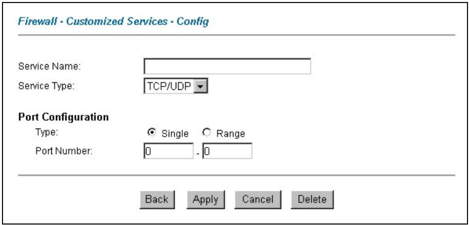
Figure 14-2 Creating/Editing A Customized Service
The next table describes the fields in this screen.
Table 14-2 Creating/Editing A Customized Service
| LABEL | DESCRIPTION |
| Service Name | Type a unique name for your custom port. |
| Service Type | Choose the IP port (TCP, UDP or TCP/UDP) that defines your customized port from the drop down list box. |
| Port Configuration | |
| Type | Click Single to specify one port only or Range to specify a span of ports that define your customized service. |
| Port Number | Type a single port number or the range of port numbers that define your customized service. |
| Back | Click Back to return to the Firewall Customized Services screen. |
| Apply | Click Apply to save your customized settings and exit this screen. |
| Cancel | Click Cancel to return to the previously saved settings. |
| Delete | Click Delete to delete the current rule. |
14.3 Example Custom Service Firewall Rule
The following Internet firewall rule example allows a hypothetical “My Service” connection from the Internet.
Step 1. Click Rule Summary under Internet to Local Network Set.
Step 2. Click a rule number to open the edit rule screen.
Step 3. Click Any in the Source Address box and then click ScrDelete.
Step 4. Click ScrAdd to open the Rule IP Config screen. Configure it as follows and click Apply.
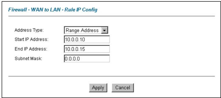
Figure 14-3 Configure Source IP Example
Step 5. Click Edit Available Service in the Edit rule screen and then click a rule number to bring up the Firewall Customized Services Config screen. Configure as follows.
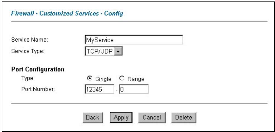
Figure 14-4 Customized Service for MyService Example
Customized services show up with an “*” before their names in the Services list box and the Rule Summary list box. Click Apply after you’ve created your customized service.
Step 6. Follow the procedures outlined earlier in this chapter to configure all your rules. Configure the rule configuration screen like the one below and apply it.
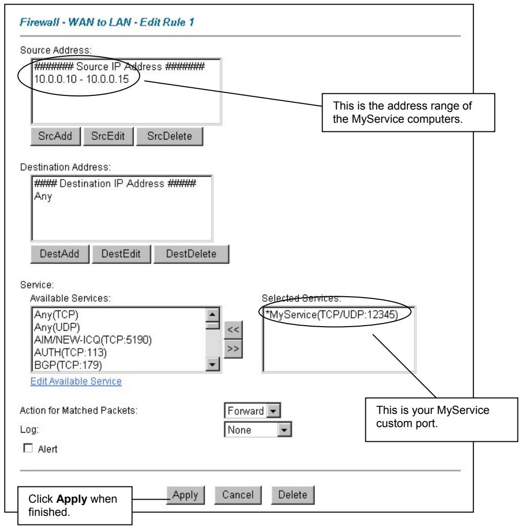
Figure 14-5 Syslog Rule Configuration Example
Step 7. On completing the configuration procedure for these Internet firewall rules, the Rule Summary screen should look like the following. Don't forget to click Apply when you have finished configuring your rule(s) to save your settings back to the Prestige.
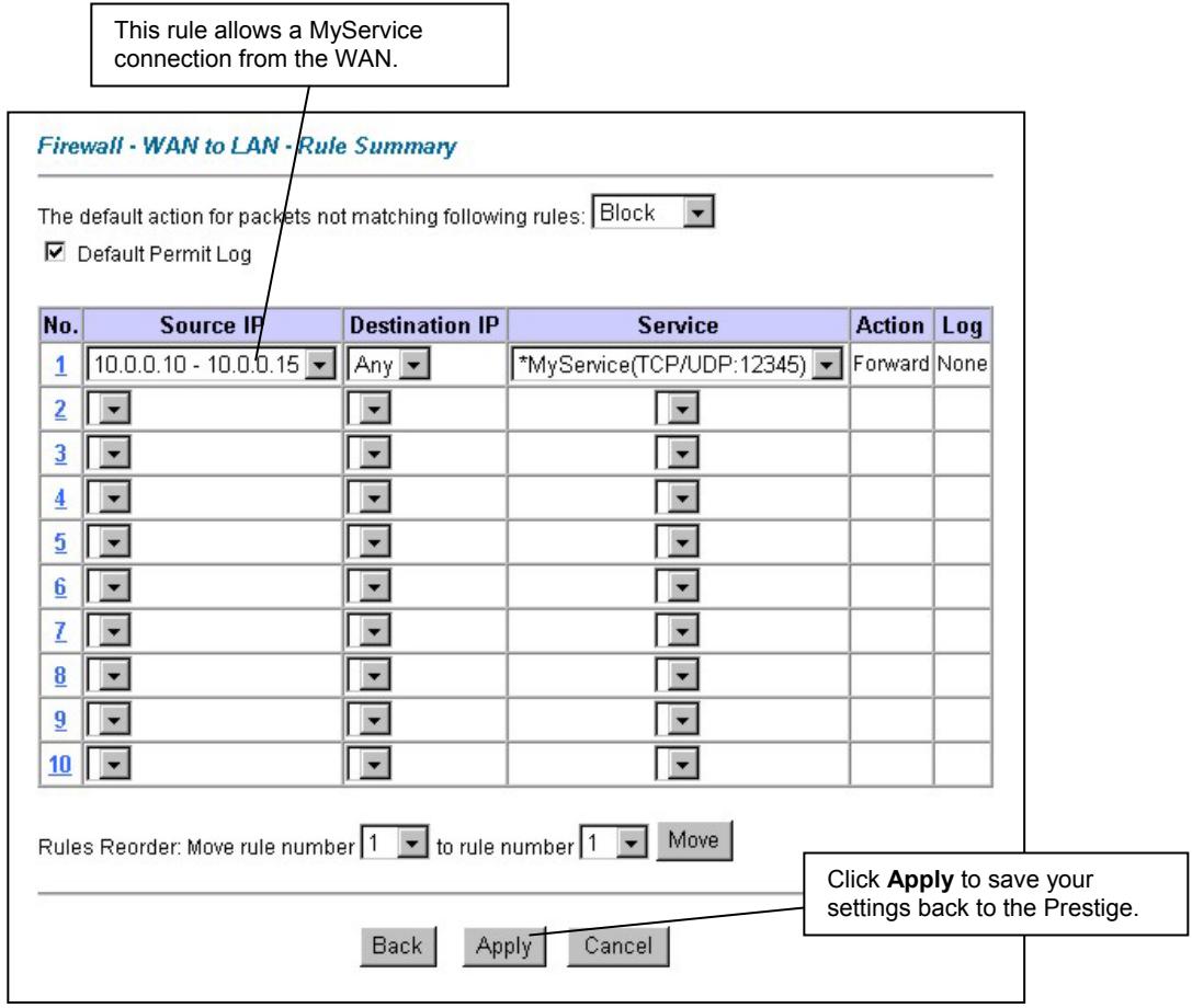
Figure 14-6 Rule Summary Example
Chapter 15
Content Filtering Screens
This chapter covers how to configure content filtering.
15.1 Content Filtering Overview
Internet content filtering allows you to create and enforce Internet access policies tailored to your needs. Content filtering gives you the ability to block web sites that contain key words (that you specify) in the URL. You can set a schedule for when the Prestige performs content filtering. You can also specify trusted IP addresses on the LAN for which the Prestige will not perform content filtering.
15.2 Configuring Keyword Blocking
Use this screen to block sites containing certain keywords in the URL. For example, if you enable the keyword "bad", the Prestige blocks all sites containing this keyword including the URL http://www.website.com/bad.html, even if it is not included in the Filter List.
To have your Prestige block Web sites containing keywords in their URLs, click Content Filter and Keyword. The screen appears as shown.

Figure 15-1 Content Filter: Keyword
The following table describes the fields in this screen.
Table 15-1 Content Filter: Keyword
| LABEL | DESCRIPTION |
| Enable Keyword Blocking | Select this check box to enable this feature. |
| Block Websites that contain these keywords in the URL: | This box contains the list of all the keywords that you have configured the Prestige to block. |
| Delete | Highlight a keyword in the box and click Delete to remove it. |
| Clear All | Click Clear All to remove all of the keywords from the list. |
| Keyword | Type a keyword in this field. You may use any character (up to 64 characters). Wildcards are not allowed. |
Table 15-1 Content Filter: Keyword
| LABEL | DESCRIPTION |
| Add Keyword | Click Add Keyword after you have typed a keyword.Repeat this procedure to add other keywords. Up to 64 keywords are allowed.When you try to access a web page containing a keyword, you will get a message telling you that the content filter is blocking this request. |
| Back | Click Back to return to the previous screen. |
| Apply | Click Apply to save your changes back to the Prestige. |
| Cancel | Click Cancel to return to the previously saved settings. |
15.3 Configuring the Schedule
To set the days and times for the Prestige to perform content filtering, click Content Filter and Schedule. The screen appears as shown.
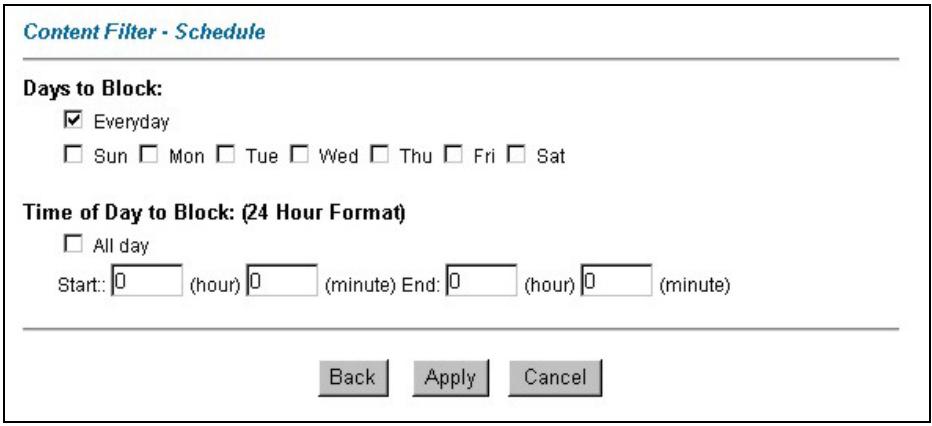
Figure 15-2 Content Filter: Schedule
The following table describes the fields in this screen.
Table 15-2 Content Filter: Schedule
| LABEL | DESCRIPTION |
| Days to Block: | Select a check box to configure which days of the week (or everyday) you want the content filtering to be active. |
| Time of Day to Block: | Use the 24 hour format to configure which time of the day (or select the All day check box) you want the content filtering to be active. |
| Back | Click Back to return to the previous screen. |
| Apply | Click Apply to save your changes. |
| Cancel | Click Cancel to return to the previously saved settings. |
15.4 Configuring Trusted Computers
To exclude a range of users on the LAN from content filtering on your Prestige, click CONTENT FILTER and Trusted. The screen appears as shown.
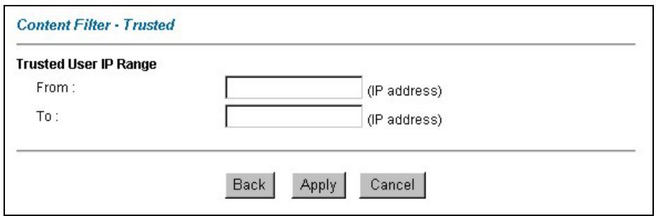
Figure 15-3 Content Filter: Trusted
The following table describes the fields in this screen.
Table 15-3 Content Filter: Trusted
| LABEL | DESCRIPTION |
| Trusted User IP Range | |
| From | Type the IP address of a computer (or the beginning IP address of a specific range of computers) on the LAN that you want to exclude from content filtering. |
Table 15-3 Content Filter: Trusted
| LABEL | DESCRIPTION |
| To | Type the ending IP address of a specific range of users on your LAN that you want to exclude from content filtering. Leave this field blank if you want to exclude an individual computer. |
| Back | Click Back to return to the previous screen. |
| Apply | Click Apply to save your changes back to the Prestige. |
| Cancel | Click Cancel to return to the previously saved settings. |
Part V:
VPN/IPSec
This part provides information about configuring VPN/IPSec for secure communications.
Chapter 16
Introduction to IPSec
This chapter introduces the basics of IPSec VPNs.
16.1 VPN Overview
A VPN (Virtual Private Network) provides secure communications between sites without the expense of leased site-to-site lines. A secure VPN is a combination of tunneling, encryption, authentication, access control and auditing technologies/services used to transport traffic over the Internet or any insecure network that uses the TCP/IP protocol suite for communication.
16.1.1 IPSec
Internet Protocol Security (IPSec) is a standards-based VPN that offers flexible solutions for secure data communications across a public network like the Internet. IPSec is built around a number of standardized cryptographic techniques to provide confidentiality, data integrity and authentication at the IP layer.
16.1.2 Security Association
A Security Association (SA) is a contract between two parties indicating what security parameters, such as keys and algorithms they will use.
16.1.3 Other Terminology
Encryption
Encryption is a mathematical operation that transforms data from "plaintext" (readable) to "ciphertext" (scrambled text) using a "key". The key and clear text are processed by the encryption operation, which leads to the data scrambling that makes encryption secure. Decryption is the opposite of encryption: it is a mathematical operation that transforms "ciphertext" to plaintext. Decryption also requires a key.
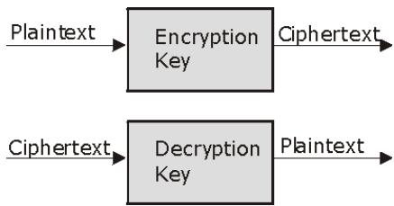
flowchart
graph LR
    A["Plaintext"] --> B["Encryption Key"]
    B --> C["Ciphertext"]
    D["Ciphertext"] --> E["Decryption Key"]
    E --> F["Plaintext"]
Figure 16-1 Encryption and Decryption
Data Confidentiality
The IPSec sender can encrypt packets before transmitting them across a network.
Data Integrity
The IPSec receiver can validate packets sent by the IPSec sender to ensure that the data has not been altered during transmission.
Data Origin Authentication
The IPSec receiver can verify the source of IPSec packets. This service depends on the data integrity service.
16.1.4 VPN Applications
The Prestige supports the following VPN applications.
- Linking Two or More Private Networks Together
Connect branch offices and business partners over the Internet with significant cost savings and improved performance when compared to leased lines between sites.
- Accessing Network Resources When NAT Is Enabled
When NAT is enabled, remote users are not able to access hosts on the LAN unless the host is designated a public LAN server for that specific protocol. Since the VPN tunnel terminates inside the LAN, remote users will be able to access all computers that use private IP addresses on the LAN.
▶ Unsupported IP Applications
A VPN tunnel may be created to add support for unsupported emerging IP applications.
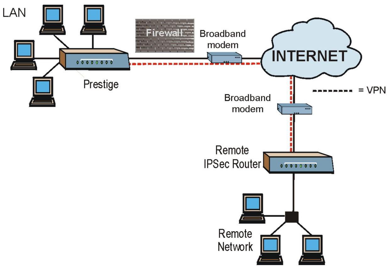
flowchart
graph TD
    A["LAN"] --> B["Prestige"]
    C["Computer"] --> B
    D["Computer"] --> B
    B --> E["Broadband modem"]
    E --> F["INTERNET"]
    G["Remote Network"] --> H["Remote IPSec Router"]
    H --> I["Internet"]
    J["Broadband modem"] -.-> K["= VPN"]
    style A fill:#f9f,stroke:#333
    style C fill:#f9f,stroke:#333
    style D fill:#f9f,stroke:#333
    style B fill:#ccf,stroke:#333
    style E fill:#ccf,stroke:#333
    style F fill:#cfc,stroke:#333
    style H fill:#cfc,stroke:#333
    style I fill:#cfc,stroke:#333
Figure 16-2 VPN Application
16.2 IPSec Architecture
The overall IPSec architecture is shown as follows.
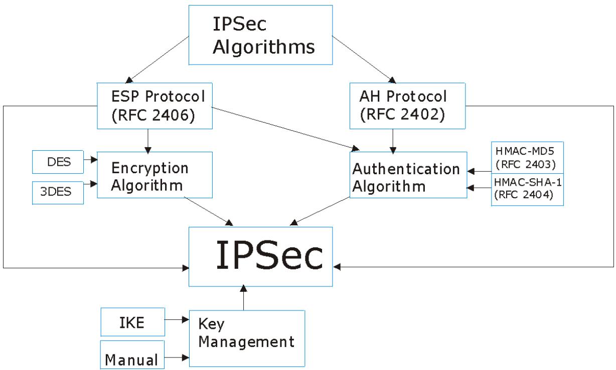
flowchart
graph TD
    A["IPSec Algorithms"] --> B["ESP Protocol (RFC 2406)"]
    A --> C["AH Protocol (RFC 2402)"]
    B --> D["Encryption Algorithm"]
    C --> E["Authentication Algorithm"]
    D --> F["IPSec"]
    E --> F
    G["DES"] --> D
    H["3DES"] --> D
    I["IKE"] --> F
    J["Manual"] --> F
    K["HMAC-MD5 (RFC 2403)"] <--> E
    L["HMAC-SHA-1 (RFC 2404)"] <--> E
    F --> M["Key Management"]
Figure 16-3 IPSec Architecture
16.2.1 IPSec Algorithms
The ESP (Encapsulating Security Payload) Protocol (RFC 2406) and AH (Authentication Header) protocol (RFC 2402) describe the packet formats and the default standards for packet structure (including implementation algorithms).
The Encryption Algorithm describes the use of encryption techniques such as DES (Data Encryption Standard) and Triple DES algorithms.
The Authentication Algorithms, HMAC-MD5 (RFC 2403) and HMAC-SHA-1 (RFC 2404, provide an authentication mechanism for the AH and ESP protocols. Please see section 17.2 for more information.
16.2.2 Key Management
Key management allows you to determine whether to use IKE (ISAKMP) or manual key configuration in order to set up a VPN.
16.3 Encapsulation
The two modes of operation for IPSec VPNs are Transport mode and Tunnel mode.
| OriginalIP Packet | IPHeader | TCPHeader | Data |
| Transport ModeProtected Packet | IPHeader | IPSecHeader | TCPHeader | Data |
| Tunnel ModeProtected Packet | IPHeader | IPSecHeader | IPHeader | TCPHeader | Data |
Figure 16-4 Transport and Tunnel Mode IPSec Encapsulation
16.3.1 Transport Mode
Transport mode is used to protect upper layer protocols and only affects the data in the IP packet. In Transport mode, the IP packet contains the security protocol (AH or ESP) located after the original IP header and options, but before any upper layer protocols contained in the packet (such as TCP and UDP). With ESP, protection is applied only to the upper layer protocols contained in the packet. The IP header information and options are not used in the authentication process. Therefore, the originating IP address cannot be verified for integrity against the data.
With the use of AH as the security protocol, protection is extended forward into the IP header to verify the integrity of the entire packet by use of portions of the original IP header in the hashing process.
16.3.2 Tunnel Mode
Tunnel mode encapsulates the entire IP packet to transmit it securely. A Tunnel mode is required for gateway services to provide access to internal systems. Tunnel mode is fundamentally an IP tunnel with authentication and encryption. This is the most common mode of operation. Tunnel mode is required for gateway to gateway and host to gateway communications. Tunnel mode communications have two sets of IP headers:
Outside header: The outside IP header contains the destination IP address of the VPN gateway.
Inside header: The inside IP header contains the destination IP address of the final system behind the VPN gateway. The security protocol appears after the outer IP header and before the inside IP header.
16.4 IPSec and NAT
Read this section if you are running IPSec on a host computer behind the Prestige.
NAT is incompatible with the AH protocol in both Transport and Tunnel mode. An IPSec VPN using the AH protocol digitally signs the outbound packet, both data payload and headers, with a hash value appended to the packet. When using AH protocol, packet contents (the data payload) are not encrypted.
A NAT device in between the IPSec endpoints will rewrite either the source or destination address with one of its own choosing. The VPN device at the receiving end will verify the integrity of the incoming packet by computing its own hash value, and complain that the hash value appended to the received packet doesn't match. The VPN device at the receiving end doesn't know about the NAT in the middle, so it assumes that the data has been maliciously altered.
IPSec using ESP in Tunnel mode encapsulates the entire original packet (including headers) in a new IP packet. The new IP packet's source address is the outbound address of the sending VPN gateway, and its destination address is the inbound address of the VPN device at the receiving end. When using ESP protocol with authentication, the packet contents (in this case, the entire original packet) are encrypted. The encrypted contents, but not the new headers, are signed with a hash value appended to the packet.
Tunnel mode ESP with authentication is compatible with NAT because integrity checks are performed over the combination of the "original header plus original payload," which is unchanged by a NAT device.
Transport mode ESP with authentication is not compatible with NAT.
Table 16-1 VPN and NAT
| SECURITY PROTOCOL | MODE | NAT |
| AH | Transport | N |
| AH | Tunnel | N |
| ESP | Transport | N |
| ESP | Tunnel | Y |
Chapter 17
VPN Screens
This chapter introduces the VPN screens. See the Logs chapter for information on viewing logs and the Reference Guide for IPSec log descriptions.
17.1 VPN/IPSec Overview
Use the screens documented in this chapter to configure rules for VPN connections and manage VPN connections.
17.2 IPSec Algorithms
The ESP and AH protocols are necessary to create a Security Association (SA), the foundation of an IPSec VPN. An SA is built from the authentication provided by the AH and ESP protocols. The primary function of key management is to establish and maintain the SA between systems. Once the SA is established, the transport of data may commence.
17.2.1 AH (Authentication Header) Protocol
AH protocol (RFC 2402) was designed for integrity, authentication, sequence integrity (replay resistance), and non-repudiation but not for confidentiality, for which the ESP was designed.
In applications where confidentiality is not required or not sanctioned by government encryption restrictions, an AH can be employed to ensure integrity. This type of implementation does not protect the information from dissemination but will allow for verification of the integrity of the information and authentication of the originator.
17.2.2 ESP (Encapsulating Security Payload) Protocol
The ESP protocol (RFC 2406) provides encryption as well as some of the services offered by AH. ESP authenticating properties are limited compared to the AH due to the non-inclusion of the IP header information during the authentication process. However, ESP is sufficient if only the upper layer protocols need to be authenticated.
An added feature of the ESP is payload padding, which further protects communications by concealing the size of the packet being transmitted.
Table 17-1 AH and ESP
| ESP | AH |
| Select DES for minimal security and 3DES for maximum. Select NULL to set up a tunnel without encryption. | Select MD5 for minimal security and SHA-1 for maximum security. |
| DES (default)Data Encryption Standard (DES) is a widely used method of data encryption using a private (secret) key. DES applies a 56-bit key to each 64-bit block of data. | MD5 (default)MD5 (Message Digest 5) produces a 128-bit digest to authenticate packet data. |
| 3DESTriple DES (3DES) is a variant of DES, which iterates three times with three separate keys (3 x 56 = 168 bits), effectively doubling the strength of DES. | SHA1SHA1 (Secure Hash Algorithm) produces a 160-bit digest to authenticate packet data. |
| Select DES for minimal security and 3DES for maximum. Select NULL to set up a tunnel without encryption. | Select MD5 for minimal security and SHA-1 for maximum security. |
17.3 My IP Address
My IP Address is the WAN IP address of the Prestige. If this field is configured as 0.0.0.0, then the Prestige will use the current Prestige WAN IP address (static or dynamic) to set up the VPN tunnel. The Prestige has to rebuild the VPN tunnel if the My IP Address changes after setup.
17.4 Secure Gateway Address
Secure Gateway Address is the WAN IP address or domain name of the remote IPSec router (secure gateway).
If the remote secure gateway has a static WAN IP address, enter it in the Secure Gateway Address field. You may alternatively enter the remote secure gateway's domain name (if it has one) in the Secure Gateway Address field.
You can also enter a remote secure gateway's domain name in the Secure Gateway Address field if the remote secure gateway has a dynamic WAN IP address and is using DDNS. The Prestige has to rebuild the VPN tunnel each time the remote secure gateway's WAN IP address changes (there may be a delay until the DDNS servers are updated with the remote gateway's new WAN IP address).
17.4.1 Dynamic Secure Gateway Address
If the remote secure gateway has a dynamic WAN IP address and does not use DDNS, enter 0.0.0.0 as the secure gateway's address. In this case only the remote secure gateway can initiate SAs. This may be useful
for telecommuters initiating a VPN tunnel to the company network. See section 17.16 for configuration examples.
The Secure Gateway IP Address may be configured as 0.0.0.0 only when using IKE key management and not Manual key management.
17.5 VPN Summary Screen
The following figure helps explain the main fields in the web configurator.
Local Network
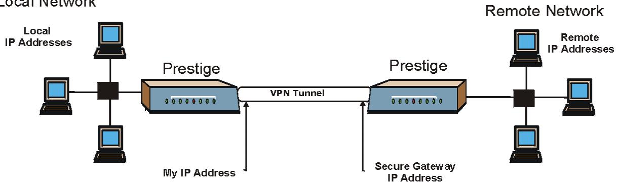
flowchart
graph LR
    A["Local IP Addresses"] --> B["Prestige"]
    C["Local IP Addresses"] --> B
    D["Local IP Addresses"] --> B
    B --> E["VPN Tunnel"]
    E --> F["Prestige"]
    G["Remote IP Addresses"] --> H["Prestige"]
    I["Remote IP Addresses"] --> H
    H --> J["Secure Gateway IP Address"]
    J --> K["My IP Address"]
Figure 17-1 IPSec Summary Fields
Local and remote IP addresses must be static.
Click VPN and Setup to open the VPN Summary screen. This is a read-only menu of your IPSec rules (tunnels). The IPSec summary menu is read-only. Edit a VPN by selecting an index number and then configuring its associated submenus.
VPN - Summary
| No. | Name | Active | Local Address | Remote Address | Encap. | IPSec Algorithm | Secure Gateway IP |
| 1 | |||||||
| 2 | |||||||
| 3 | |||||||
| 4 | |||||||
| 5 | |||||||
| 6 | |||||||
| 7 | |||||||
| 8 | |||||||
| 9 | |||||||
| 10 |
Back
Figure 17-2 VPN Summary
The following table describes the fields in this screen.
Table 17-2 VPN Summary
| LABEL | DESCRIPTION |
| No. | This is the VPN policy index number. Click a number to edit VPN policies. |
| Name | This field displays the identification name for this VPN policy. |
| Active | This field displays whether the VPN policy is active or not. A "Y" signifies that this VPN policy is active. |
| Local Address | This is the IP address(es) of computers on your local network behind your Prestige. |
| Remote Address | This is the IP address(Es) of computers on the remote network behind the remote IPSec router. |
| Encap. | This field displaysTunnel or Transport mode. |
| IPSec Algorithm | This field displays the security protocols used for an SA.Both AH and ESP increase Prestige processing requirements and communications latency (delay). |
Table 17-2 VPN Summary
| LABEL | DESCRIPTION |
| Secure Gateway IP | This is the IP address of the remote IPSec router. This must be a fixed, public IP address for traffic going through the Internet. |
| Back | Click Back to return to the previous screen. |
17.6 Keep Alive
When you initiate an IPSec tunnel with keep alive enabled, the Prestige automatically renegotiates the tunnel when the IPSec SA lifetime period expires (see section 17.10 for more on the IPSec SA lifetime). In effect, the IPSec tunnel becomes an “always on” connection after you initiate it. Both IPSec routers must have a Prestige-compatible keep alive feature enabled in order for this feature to work.
If the Prestige has its maximum number of simultaneous IPSec tunnels connected to it and they all have keep alive enabled, then no other tunnels can take a turn connecting to the Prestige because the Prestige never drops the tunnels that are already connected. Check Table 1-1 Model Specific Features in chapter 1 to see how many simultaneous IPSec SAs your Prestige model can support.
When there is outbound traffic with no inbound traffic, the Prestige automatically drops the tunnel after two minutes.
17.7 ID Type and Content
With aggressive negotiation mode (see section 17.10.1), the Prestige identifies incoming SAs by ID type and content since this identifying information is not encrypted. This enables the Prestige to distinguish between multiple rules for SAs that connect from remote IPSec routers that have dynamic WAN IP addresses. Telecommuters can use separate passwords to simultaneously connect to the Prestige from IPSec routers with dynamic IP addresses (see section 17.16.2 for a telecommuter configuration example).
With main mode (see section 17.10.1), the ID type and content are encrypted to provide identity protection. In this case the Prestige can only distinguish between up to eight different incoming SAs that connect from remote IPSec routers that have dynamic WAN IP addresses. The Prestige can distinguish up to eight incoming SAs because you can select between two encryption algorithms (DES and 3DES), two authentication algorithms (MD5 and SHA1) and two key groups (DH1 and DH2) when you configure a VPN rule (see section 17.11). The ID type and content act as an extra level of identification for incoming SAs.
The type of ID can be a domain name, an IP address or an e-mail address. The content is the IP address, domain name, or e-mail address.
Table 17-3 Local ID Type and Content Fields
| LOCAL ID TYPE= | CONTENT= |
| IP | Type the IP address of your computer or leave the field blank to have the Prestige automatically use its own IP address. |
| DNS | Type a domain name (up to 31 characters) by which to identify this Prestige. |
| Type an e-mail address (up to 31 characters) by which to identify this Prestige. | |
| The domain name or e-mail address that you use in theContentfield is used for identification purposes only and does not need to be a real domain name or e-mail address. | |
Table 17-4 Peer ID Type and Content Fields
| PEER ID TYPE= | CONTENT= |
| IP | Type the IP address of the computer with which you will make the VPN connection or leave the field blank to have the Prestige automatically use the address in theSecure Gatewayfield. |
| DNS | Type a domain name (up to 31 characters) by which to identify the remote IPSec router. |
| Type an e-mail address (up to 31 characters) by which to identify the remote IPSec router. | |
| The domain name or e-mail address that you use in theContentfield is used for identification purposes only and does not need to be a real domain name or e-mail address. The domain name also does not have to match the remote router’s IP address or what you configure in theSecure Gateway Addrfield below. | |
17.7.1 ID Type and Content Examples
Two IPSec routers must have matching ID type and content configuration in order to set up a VPN tunnel. The two Prestiges in this example can complete negotiation and establish a VPN tunnel.
Table 17-5 Matching ID Type and Content Configuration Example
| PRESTIGE A | PRESTIGE B |
| Local ID type: E-mail | Local ID type: IP |
| Local ID content: tom@yourcompany.com | Local ID content: 1.1.1.2 |
| Peer ID type: IP | Peer ID type: E-mail |
| Peer ID content: 1.1.1.2 | Peer ID content: tom@yourcompany.com |
The two Prestiges in this example cannot complete their negotiation because Prestige B's Local ID type is IP, but Prestige A's Peer ID type is set to E-mail. An “ID mismatched” message displays in the IPSEC LOG.
Table 17-6 Mismatching ID Type and Content Configuration Example
| PRESTIGE A | PRESTIGE B |
| Local ID type: IP | Local ID type: IP |
| Local ID content: 1.1.1.10 | Local ID content: 1.1.1.10 |
| Peer ID type: E-mail | Peer ID type: IP |
| Peer ID content: aa@yahoo.com | Peer ID content: N/A |
17.8 Pre-Shared Key
A pre-shared key identifies a communicating party during a phase 1 IKE negotiation (see section 17.10 for more on IKE phases). It is called “pre-shared” because you have to share it with another party before you can communicate with them over a secure connection.
17.9 Editing VPN Policies
Click a number (No.) on the Summary screen to edit VPN policies.
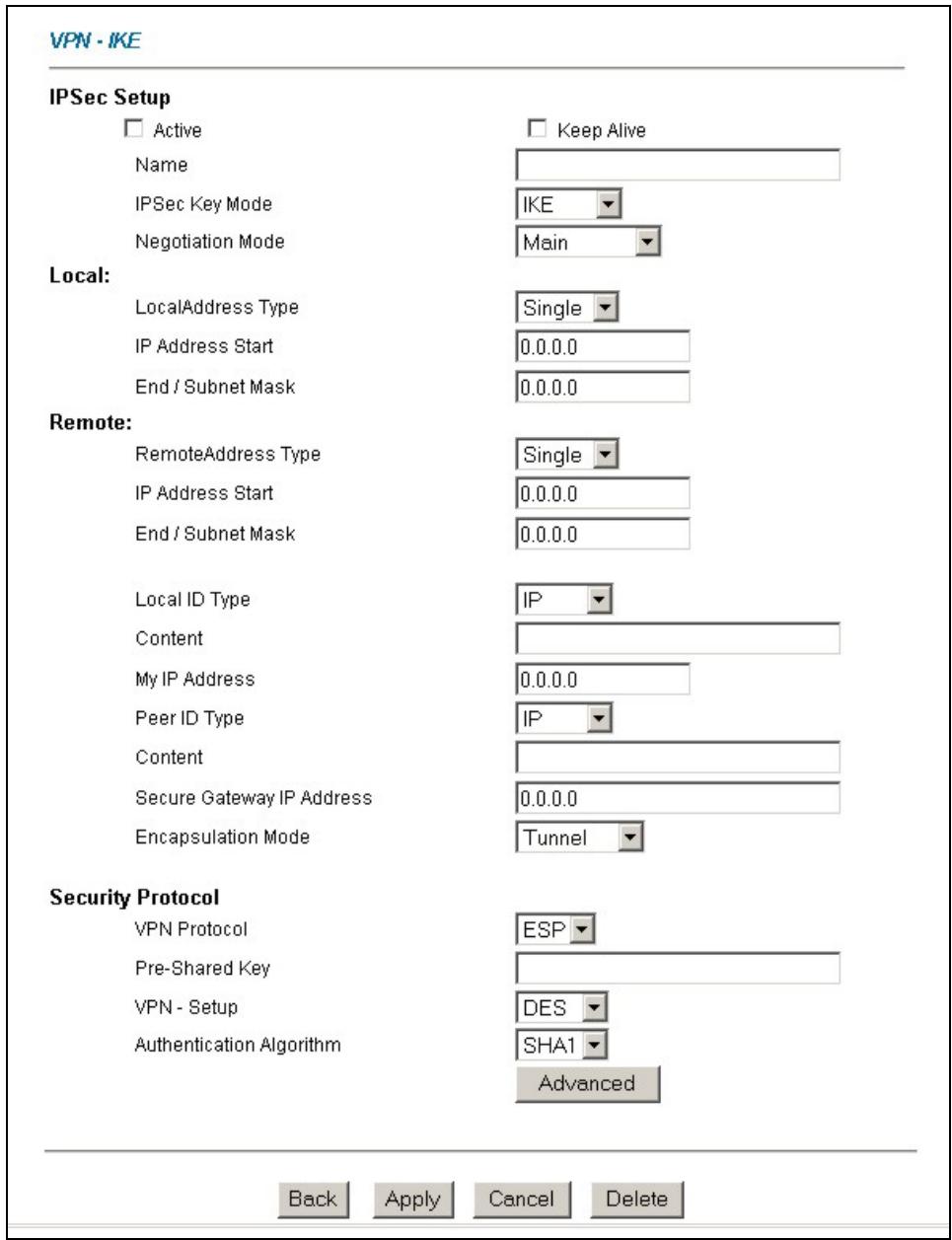
Figure 17-3 VPN IKE
The following table describes the fields in this screen.
Table 17-7 VPN IKE
| LABEL | DESCRIPTION |
| IPSec Setup | |
| Active | Select this check box to activate this VPN policy. |
| Keep Alive | Select either Yes or No from the drop-down list box.Select Yes to have the Prestige automatically reinitiate the SA after the SA lifetime times out, even if there is no traffic. The remote IPSec router must also have keep alive enabled in order for this feature to work. |
| Name | Type up to 32 characters to identify this VPN policy. You may use any character, including spaces, but the Prestige drops trailing spaces. |
| IPSec Key Mode | Select IKE or Manual from the drop-down list box.Manual is a useful option for troubleshooting if you have problems using IKE key management. |
| Negotiation Mode | Select Main or Aggressive from the drop-down list box. Multiple SAs connecting through a secure gateway must have the same negotiation mode. |
| Local | Local IP addresses must be static and correspond to the remote IPSec router's configured remote IP addresses.Two active SAs cannot have the local and remote IP address(es) both the same. Two active SAs can have the same local or remote IP address, but not both. You can configure multiple SAs between the same local and remote IP addresses, as long as only one is active at any time. |
| Local Address Type | Use the drop-down menu to choose Single, Range, or Subnet. Select Single for a single IP address. Select Range for a specific range of IP addresses. Select Subnet to specify IP addresses on a network by their subnet mask. |
| IP Address Start | When the Local Address Type field is configured to Single, enter a (static) IP address on the LAN behind your Prestige. When the Local Address Type field is configured to Range, enter the beginning (static) IP address, in a range of computers on your LAN behind your Prestige. When the Local Address Type field is configured to Subnet, this is a (static) IP address on the LAN behind your Prestige. |
Table 17-7 VPN IKE
| LABEL | DESCRIPTION |
| End / Subnet Mask | When the Local Address Type field is configured to Single, enter the IP address in the IP Address Start field again here. When the Local Address Type field is configured to Range, enter the end (static) IP address, in a range of computers on the LAN behind your Prestige. When the Local Address Type field is configured to Subnet, this is a subnet mask on the LAN behind your Prestige. |
| Remote | Remote IP addresses must be static and correspond to the remote IPSec router's configured local IP addresses. The remote fields do not apply when the Secure Gateway IP Address field is configured to 0.0.0.0. In this case only the remote IPSec router can initiate the VPN.Two active SAs cannot have the local and remote IP address(Es) both the same. Two active SAs can have the same local or remote IP address, but not both. You can configure multiple SAs between the same local and remote IP addresses, as long as only one is active at any time. |
| Remote Address Type | Use the drop-down menu to choose Single, Range, or Subnet. Select Single with a single IP address. Select Range for a specific range of IP addresses. Select Subnet to specify IP addresses on a network by their subnet mask. |
| IP Address Start | When the Remote Address Type field is configured to Single, enter a (static) IP address on the network behind the remote IPSec router. When the Remote Address Type field is configured to Range, enter the beginning (static) IP address, in a range of computers on the network behind the remote IPSec router. When the Remote Address Type field is configured to Subnet, enter a (static) IP address on the network behind the remote IPSec router. |
| End / Subnet Mask | When the Remote Address Type field is configured to Single, enter the IP address in the IP Address Start field again here. When the Remote Address Type field is configured to Range, enter the end (static) IP address, in a range of computers on the network behind the remote IPSec router. When the Remote Address Type field is configured to Subnet, enter a subnet mask on the network behind the remote IPSec router. |
| Local ID Type | Select IP to identify this Prestige by its IP address.Select DNS to identify this Prestige by a domain name.Select E-mail to identify this Prestige by an e-mail address. |
Table 17-7 VPN IKE
| LABEL | DESCRIPTION |
| Content | When you select IP in the Local ID Type field, type the IP address of your computer or leave the field blank to have the Prestige automatically use its own IP address.When you select DNS in the Local ID Type field, type a domain name (up to 31 characters) by which to identify this Prestige.When you select E-mail in the Local ID Type field, type an e-mail address (up to 31 characters) by which to identify this Prestige.The domain name or e-mail address that you use in the Content field is used for identification purposes only and does not need to be a real domain name or e-mail address. |
| My IP Address | Enter the WAN IP address of your Prestige. The Prestige uses its current WAN IP address (static or dynamic) in setting up the VPN tunnel if you leave this field as 0.0.0.0. The VPN tunnel has to be rebuilt if this IP address changes. |
| Peer ID Type | Select IP to identify the remote IPSec router by its IP address.Select DNS to identify the remote IPSec router by a domain name.Select E-mail to identify the remote IPSec router by an e-mail address. |
| Content | When you select IP in the Peer ID Type field, type the IP address of the computer with which you will make the VPN connection or leave the field blank to have the Prestige automatically use the address in the Secure Gateway IP Address field.When you select DNS in the Peer ID Type field, type a domain name (up to 31 characters) by which to identify the remote IPSec router.When you select E-mail in the Peer ID Type field, type an e-mail address (up to 31 characters) by which to identify the remote IPSec router.The domain name or e-mail address that you use in the Content field is used for identification purposes only and does not need to be a real domain name or e-mail address. The domain name also does not have to match the remote router's IP address or what you configure in the Secure Gateway IP Address field. |
| Secure Gateway IP Address | Type the WAN IP address or the URL (up to 31 characters) of the IPSec router with which you're making the VPN connection. Set this field to 0.0.0.0 if the remote IPSec router has a dynamic WAN IP address (the IPSec Key Mode field must be set to IKE). |
| Encapsulation Mode | Select Tunnel mode or Transport mode from the drop-down list box. |
Table 17-7 VPN IKE
| LABEL | DESCRIPTION |
| Security Protocol | |
| VPN Protocol | Select ESP if you want to use ESP (Encapsulation Security Payload). The ESP protocol (RFC 2406) provides encryption as well as some of the services offered by AH. If you select ESP here, you must select options from the VPN Setup and Authentication Algorithm fields (described next). |
| Pre-Shared Key | Type your pre-shared key in this field. A pre-shared key identifies a communicating party during a phase 1 IKE negotiation. It is called "pre-shared" because you have to share it with another party before you can communicate with them over a secure connection. Multiple SAs connecting through a secure gateway must have the same pre-shared key. |
| VPN - Setup | Select DES, 3DES or NULL from the drop-down list box.When DES is used for data communications, both sender and receiver must know the same secret key, which can be used to encrypt and decrypt the message or to generate and verify a message authentication code. The DES encryption algorithm uses a 56-bit key. Triple DES (3DES) is a variation on DES that uses a 168-bit key. As a result, 3DES is more secure than DES. It also requires more processing power, resulting in increased latency and decreased throughput. Select NULL to set up a tunnel without encryption. When you select NULL, you do not enter an encryption key. |
| Authentication Algorithm | Select SHA1 or MD5 from the drop-down list box. MD5 (Message Digest 5) and SHA1 (Secure Hash Algorithm) are hash algorithms used to authenticate packet data. The SHA1 algorithm is generally considered stronger than MD5, but is slower. Select MD5 for minimal security and SHA-1 for maximum security. |
| Advanced | Click Advanced to configure more detailed settings of your IKE key management. |
| Back | Click Back to return to the previous screen. |
| Apply | Click Apply to save your changes back to the Prestige. |
| Cancel | Click Cancel to begin configuring this screen afresh. |
| Delete | Click Delete to delete the current rule. |
17.10 IKE Phases
There are two phases to every IKE (Internet Key Exchange) negotiation – phase 1 (Authentication) and phase 2 (Key Exchange). A phase 1 exchange establishes an IKE SA and the second one uses that SA to negotiate SAs for IPSec.
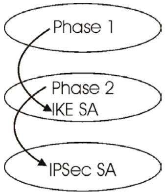
flowchart
graph TD
    A["Phase 1"] --> B["Phase 2 IKE SA"]
    B --> C["IPSec SA"]
Figure 17-4 Two Phases to Set Up the IPSec SA
In phase 1 you must:
Choose a negotiation mode.
➢ Authenticate the connection by entering a pre-shared key.
Choose an encryption algorithm.
Choose an authentication algorithm.
Choose a Diffie-Hellman public-key cryptography key group (DH1 or DH2).
➢ Set the IKE SA lifetime. This field allows you to determine how long an IKE SA should stay up before it times out. An IKE SA times out when the IKE SA lifetime period expires. If an IKE SA times out when an IPSec SA is already established, the IPSec SA stays connected.
In phase 2 you must:
Choose which protocol to use (ESP or AH) for the IKE key exchange.
Choose an encryption algorithm.
Choose an authentication algorithm
➢ Choose whether to enable Perfect Forward Secrecy (PFS) using Diffie-Hellman public-key cryptography – see section 17.10.3. Select None (the default) to disable PFS.
Choose Tunnel mode or Transport mode.
Set the IPSec SA lifetime. This field allows you to determine how long the IPSec SA should stay up before it times out. The Prestige automatically renegotiates the IPSec SA if there is traffic when the IPSec SA lifetime period expires. The Prestige also automatically renegotiates the IPSec SA if both IPSec routers have keep alive enabled, even if there is no traffic. If an IPSec SA times out, then the IPSec router must renegotiate the SA the next time someone attempts to send traffic.
17.10.1 Negotiation Mode
The phase 1 Negotiation Mode you select determines how the Security Association (SA) will be established for each connection through IKE negotiations.
➢ Main Mode ensures the highest level of security when the communicating parties are negotiating authentication (phase 1). It uses 6 messages in three round trips: SA negotiation, Diffie-Hellman exchange and an exchange of nonces (a nonce is a random number). This mode features identity protection (your identity is not revealed in the negotiation).
Aggressive Mode is quicker than Main Mode because it eliminates several steps when the communicating parties are negotiating authentication (phase 1). However the trade-off is that faster speed limits its negotiating power and it also does not provide identity protection. It is useful in remote access situations where the address of the initiator is not known by the responder and both parties want to use pre-shared key authentication.
17.10.2 Diffie-Hellman (DH) Key Groups
Diffie-Hellman (DH) is a public-key cryptography protocol that allows two parties to establish a shared secret over an unsecured communications channel. Diffie-Hellman is used within IKE SA setup to establish session keys. 768-bit (Group 1 - DH1) and 1024-bit (Group 2 - DH2) Diffie-Hellman groups are supported. Upon completion of the Diffie-Hellman exchange, the two peers have a shared secret, but the IKE SA is not authenticated. For authentication, use pre-shared keys.
17.10.3 Perfect Forward Secrecy (PFS)
Enabling PFS means that the key is transient. The key is thrown away and replaced by a brand new key using a new Diffie-Hellman exchange for each new IPSec SA setup. With PFS enabled, if one key is compromised, previous and subsequent keys are not compromised, because subsequent keys are not derived from previous keys. The (time-consuming) Diffie-Hellman exchange is the trade-off for this extra security.
This may be unnecessary for data that does not require such security, so PFS is disabled (None) by default in the Prestige. Disabling PFS means new authentication and encryption keys are derived from the same root secret (which may have security implications in the long run) but allows faster SA setup (by bypassing the Diffie-Hellman key exchange).
17.11 Configuring Advanced IKE Settings
Click Advanced in the VPN IKE screen. This is the VPN IKE- Advanced screen as shown next.
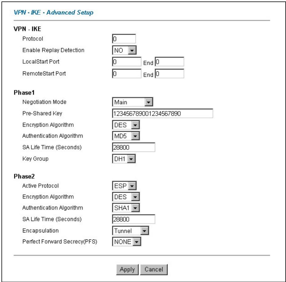
Figure 17-5 VPN IKE: Advanced
The following table describes the fields in this screen.
Table 17-8 VPN IKE: Advanced
| LABEL | DESCRIPTION |
| VPN - IKE | |
| Protocol | Enter 1 for ICMP, 6 for TCP, 17 for UDP, etc. 0 is the default and signifies any protocol. |
Table 17-8 VPN IKE: Advanced
| LABEL | DESCRIPTION |
| Enable Replay Protection | As a VPN setup is processing intensive, the system is vulnerable to Denial of Service (DoS) attacks The IPSec receiver can detect and reject old or duplicate packets to protect against replay attacks. Select YES from the drop-down menu to enable replay detection, or select NO to disable it. |
| Local Start Port | 0 is the default and signifies any port. Type a port number from 0 to 65535. Some of the most common IP ports are: 21, FTP; 53, DNS; 23, Telnet; 80, HTTP; 25, SMTP; 110, POP3. |
| End | Enter a port number in this field to define a port range. This port number must be greater than that specified in the previous field. If Local Start Port is left at 0, End will also remain at 0. |
| Remote Start Port | 0 is the default and signifies any port. Type a port number from 0 to 65535. Some of the most common IP ports are: 21, FTP; 53, DNS; 23, Telnet; 80, HTTP; 25, SMTP; 110, POP3. |
| End | Enter a port number in this field to define a port range. This port number must be greater then that specified in the previous field. If Remote Start Port is left at 0, End will also remain at 0. |
| Phase 1 | |
| Negotiation Mode | Select Main or Aggressive from the drop-down list box. Multiple SAs connecting through a secure gateway must have the same negotiation mode. |
| Pre-Shared Key | Type your pre-shared key in this field. A pre-shared key identifies a communicating party during a phase 1 IKE negotiation. It is called "pre-shared" because you have to share it with another party before you can communicate with them over a secure connection.Type from 8 to 31 case-sensitive ASCII characters or from 16 to 62 hexadecimal ("0-9", "A-F") characters. You must precede a hexadecimal key with a "0x" (zero x), which is not counted as part of the 16 to 62 character range for the key. For example, in "0x0123456789ABCDEF", "0x" denotes that the key is hexadecimal and "0123456789ABCDEF" is the key itself.Both ends of the VPN tunnel must use the same pre-shared key. You will receive a "PYLD_MALFORMED" (payload malformed) packet if the same pre-shared key is not used on both ends. |
Table 17-8 VPN IKE: Advanced
| LABEL | DESCRIPTION |
| Encryption Algorithm | Select DES or 3DES from the drop-down list box.When DES is used for data communications, both sender and receiver must know the same secret key, which can be used to encrypt and decrypt the message or to generate and verify a message authentication code. The DES encryption algorithm uses a 56-bit key. Triple DES (3DES) is a variation on DES that uses a 168-bit key. As a result, 3DES is more secure than DES. It also requires more processing power, resulting in increased latency and decreased throughput. |
| Authentication Algorithm | Select SHA1 or MD5 from the drop-down list box. MD5 (Message Digest 5) and SHA1 (Secure Hash Algorithm) are hash algorithms used to authenticate packet data. The SHA1 algorithm is generally considered stronger than MD5, but is slower. Select MD5 for minimal security and SHA-1 for maximum security. |
| SA Life Time (Seconds) | Define the length of time before an IKE SA automatically renegotiates in this field. It may range from 60 to 3,000,000 seconds (almost 35 days).A short SA Life Time increases security by forcing the two VPN gateways to update the encryption and authentication keys. However, every time the VPN tunnel renegotiates, all users accessing remote resources are temporarily disconnected. |
| Key Group | You must choose a key group for phase 1 IKE setup. DH1 (default) refers to Diffie-Hellman Group 1 a 768 bit random number. DH2 refers to Diffie-Hellman Group 2 a 1024 bit (1Kb) random number. |
| Phase 2 | |
| Active Protocol | Use the drop-down list box to choose from ESP or AH. |
| Encryption Algorithm | Select DES, 3DES or NULL from the drop-down list box.When DES is used for data communications, both sender and receiver must know the same secret key, which can be used to encrypt and decrypt the message or to generate and verify a message authentication code. The DES encryption algorithm uses a 56-bit key. Triple DES (3DES) is a variation on DES that uses a 168-bit key. As a result, 3DES is more secure than DES. It also requires more processing power, resulting into increased latency and decreased throughput. Select NULL to set up a tunnel without encryption. When you select NULL, you do not enter an encryption key. |
Table 17-8 VPN IKE: Advanced
| LABEL | DESCRIPTION |
| Authentication Algorithm | Select SHA1 or MD5 from the drop-down list box. MD5 (Message Digest 5) and SHA1 (Secure Hash Algorithm) are hash algorithms used to authenticate packet data. The SHA1 algorithm is generally considered stronger than MD5, but is slower. Select MD5 for minimal security and SHA-1 for maximum security. |
| SA Life Time (Seconds) | Define the length of time before an IKE SA automatically renegotiates in this field. It may range from 60 to 3,000,000 seconds (almost 35 days).A short SA Life Time increases security by forcing the two VPN gateways to update the encryption and authentication keys. However, every time the VPN tunnel renegotiates, all users accessing remote resources are temporarily disconnected. |
| Encapsulation | Select Tunnel mode or Transport mode from the drop-down list box. |
| Perfect Forward Secrecy (PFS) | Perfect Forward Secrecy (PFS) is disabled (NONE) by default in phase 2 IPSec SA setup. This allows faster IPSec setup, but is not so secure. Choose DH1 or DH2 from the drop-down list box to enable PFS. DH1 refers to Diffie-Hellman Group 1 a 768 bit random number. DH2 refers to Diffie-Hellman Group 2 a 1024 bit (1Kb) random number (more secure, yet slower). |
| Apply | Click Apply to save your changes back to the Prestige and return to the VPN IKE screen. |
| Cancel | Click Cancel to return to the VPN IKE screen without saving your changes. |
17.12 Manual Key Setup
Manual key management is useful if you have problems with IKE key management.
17.12.1 Security Parameter Index (SPI)
An SPI is used to distinguish different SAs terminating at the same destination and using the same IPSec protocol. This data allows for the multiplexing of SAs to a single gateway. The SPI (Security Parameter Index) along with a destination IP address uniquely identify a particular Security Association (SA). The SPI is transmitted from the remote VPN gateway to the local VPN gateway. The local VPN gateway then uses the network, encryption and key values that the administrator associated with the SPI to establish the tunnel.
Current ZyXEL implementation assumes identical outgoing and incoming SPIs.
17.13Configuring Manual Key
You only configure VPN Manual Key when you select Manual in the Key Management field on the VPN IKE screen. This is the VPN Manual Key screen as shown next.
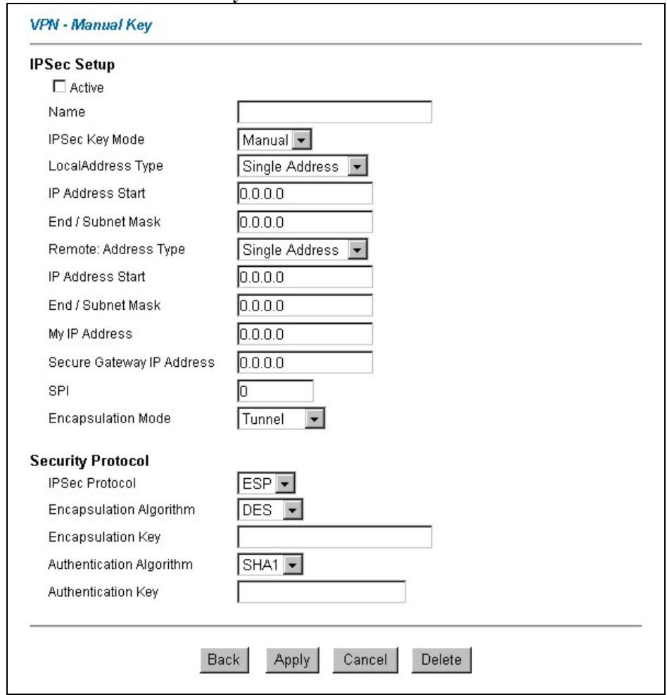
Figure 17-6 Manual Setup
The following table describes the fields in this screen.
Table 17-9 VPN Manual Setup
| LABEL | DESCRIPTION |
| Active | Select this check box to activate this VPN policy. |
| Name | Type up to 32 characters to identify this VPN policy. You may use any character, including spaces, but the Prestige drops trailing spaces. |
| IPSec Key Mode | Select IKE or Manual from the drop-down list box.Manualis a useful option for troubleshooting if you have problems using IKEkey management. |
| Local | Local IP addresses must be static and correspond to the remote IPSec router's configured remote IP addresses.Two active SAs cannot have the local and remote IP address(es) both the same. Two active SAs can have the same local or remote IP address, but not both. You can configure multiple SAs between the same local and remote IP addresses, as long as only one is active at any time. |
| Local Address Type | Use the drop-down menu to choose Single, Range, or Subnet. Select Singlefor a single IP address. Select Rangefor a specific range of IP addresses. Select Subnetto specify IP addresses on a network by their subnet mask. |
| IP Address Start | When the Local Address Typefield is configured to Single, enter a (static) IP address on the LAN behind your Prestige. When the Local Address Typefield is configured to Range, enter the beginning (static) IP address, in a range of computers on your LAN behind your Prestige. When the Local Address Typefield is configured to Subnet, this is a (static) IP address on the LAN behind your Prestige. |
| End / Subnet Mask | When the Local Address Typefield is configured to Single, enter the IP address in the IP Address Startfield again here. When the Local Address Typefield is configured to Range, enter the end (static) IP address, in a range of computers on the LAN behind your Prestige. When the Local Address Typefield is configured to Subnet, this is a subnet mask on the LAN behind your Prestige. |
| Remote | Remote IP addresses must be static and correspond to the remote IPSec router's configured local IP addresses. The remote fields do not apply when the Secure Gateway IP Addressfield is configured to 0.0.0.0. In this case only the remote IPSec router can initiate the VPN.Two active SAs cannot have the local and remote IP address(es) both the same. Two active SAs can have the same local or remote IP address, but not both. You can configure multiple SAs between the same local and remote IP addresses, as long as only one is active at any time. |
Table 17-9 VPN Manual Setup
| LABEL | DESCRIPTION |
| Remote Address Type | Use the drop-down menu to choose Single, Range, or Subnet. Select Single with a single IP address. Select Range for a specific range of IP addresses. Select Subnet to specify IP addresses on a network by their subnet mask. |
| IP Address Start | When the Remote Address Type field is configured to Single, enter a (static) IP address on the network behind the remote IPSec router. When the Remote Address Type field is configured to Range, enter the beginning (static) IP address, in a range of computers on the network behind the remote IPSec router. When the Remote Address Type field is configured to Subnet, enter a (static) IP address on the network behind the remote IPSec router. |
| End / Subnet Mask | When the Remote Address Type field is configured to Single, enter the IP address in the IP Address Start field again here. When the Remote Address Type field is configured to Range, enter the end (static) IP address, in a range of computers on the network behind the remote IPSec router. When the Remote Address Type field is configured to Subnet, enter a subnet mask on the network behind the remote IPSec router. |
| My IP Address | Enter the WAN IP address of your Prestige. The Prestige uses its current WAN IP address (static or dynamic) in setting up the VPN tunnel if you leave this field as 0.0.0.0. The VPN tunnel has to be rebuilt if this IP address changes. |
| Secure Gateway IP Address | Type the WAN IP address or the URL (up to 31 characters) of the IPSec router with which you're making the VPN connection. Set this field to 0.0.0.0 if the remote IPSec router has a dynamic WAN IP address (the IPSec Key Mode field must be set to IKE). |
| SPI | Type a unique SPI from one to four characters long. Valid Characters are "0, 1, 2, 3, 4, 5, 6, 7, 8, and 9". |
| Encapsulation Mode | Select Tunnel mode or Transport mode from the drop-down list box. |
| IPSec Protocol | Select ESP if you want to use ESP (Encapsulation Security Payload). The ESP protocol (RFC 2406) provides encryption as well as some of the services offered by AH. If you select ESP here, you must select options from the Authentication Algorithm field (described later). |
Table 17-9 VPN Manual Setup
| LABEL | DESCRIPTION |
| Encapsulation Algorithm | Select DES, 3DES or NULL from the drop-down list box.When DES is used for data communications, both sender and receiver must know the same secret key, which can be used to encrypt and decrypt the message or to generate and verify a message authentication code. The DES encryption algorithm uses a 56-bit key. Triple DES (3DES) is a variation on DES that uses a 168-bit key. As a result, 3DES is more secure than DES. It also requires more processing power, resulting in increased latency and decreased throughput. Select NULL to set up a tunnel without encryption. When you select NULL, you do not enter an encryption key. |
| Encapsulation Key (only with ESP) | With DES, type a unique key 8 characters long. With 3DES, type a unique key 24 characters long. Any characters may be used, including spaces, but trailing spaces are truncated. |
| Authentication Algorithm | Select SHA1 or MD5 from the drop-down list box. MD5 (Message Digest 5) and SHA1 (Secure Hash Algorithm) are hash algorithms used to authenticate packet data. The SHA1 algorithm is generally considered stronger than MD5, but is slower. Select MD5 for minimal security and SHA-1 for maximum security. |
| Authentication Key | Type a unique authentication key to be used by IPSec if applicable. Enter 16 characters for MD5 authentication or 20 characters for SHA-1 authentication. Any characters may be used, including spaces, but trailing spaces are truncated. |
| Back | Click Back to return to the previous screen. |
| Apply | Click Apply to save your changes back to the Prestige. |
| Cancel | Click Cancel to begin configuring this screen afresh. |
| Delete | Click Delete to remove the current rule. |
17.14Viewing SA Monitor
Click VPN and Monitor to open the SA Monitor screen as shown. Use this screen to display and manage active VPN connections.
A Security Association (SA) is the group of security settings related to a specific VPN tunnel. This screen displays active VPN connections. Use Refresh to display active VPN connections. This screen is read-only. The following table describes the fields in this tab.
When there is outbound traffic but no inbound traffic, the SA times out automatically after two minutes. A tunnel with no outbound or inbound traffic is "idle" and does not timeout until the SA lifetime period expires. See section 17.6 on keep alive to have the Prestige renegotiate an IPSec SA when the SA lifetime expires, even if there is no traffic.
VPN - SA Monitor
| No. | Name | Encapsulation | IP Sec Algorithm | Disconnect |
| 1 | - | - | - | ○ |
| 2 | - | - | - | ○ |
| 3 | - | - | - | ○ |
| 4 | - | - | - | ○ |
| 5 | - | - | - | ○ |

Figure 17-7 SA Monitor
The following table describes the fields in this screen.
Table 17-10 SA Monitor
| LABEL | DESCRIPTION |
| No | This is the security association index number. |
| Name | This field displays the identification name for this VPN policy. |
| Encapsulation | This field displays Tunnel or Transport mode. |
| IPSec Algorithm | This field displays the security protocols used for an SA.Both AH and ESP increase Prestige processing requirements and communications latency (delay). |
| Disconnect | Select Disconnect next to a security association and then click Apply to stop that security association. |
| Back | Click Back to return to the previous screen. |
| Apply | Click Apply to save your changes back to the Prestige. |
Table 17-10 SA Monitor
| LABEL | DESCRIPTION |
| Refresh | Click Refresh to display the current active VPN connection(s). |
17.15Configuring Global Setting
To change your Prestige's global settings, click VPN and then Global Setting. The screen appears as shown.
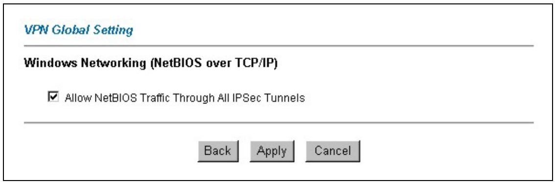
Figure 17-8 Global Setting
The following table describes the fields in this screen.
Table 17-11 Global Setting
| LABEL | DESCRIPTION |
| Windows Networking (NetBIOS over TCP/IP) | NetBIOS (Network Basic Input/Output System) are TCP or UDP broadcast packets that enable a computer to find other computers. It may sometimes be necessary to allow NetBIOS packets to pass through VPN tunnels in order to allow local computers to find computers on the remote network and vice versa. |
| Allow NetBIOS Traffic Through All IP/Sec Tunnels | Select this check box to send NetBIOS packets through the VPN connection. |
| Back | Click Back to return to the previous screen. |
| Apply | Click Apply to save your changes back to the Prestige. |
| Cancel | Click Cancel to begin configuring this screen afresh. |
17.16 Telecommuter VPN/IPSec Examples
The following examples show how multiple telecommuters can make VPN connections to a single Prestige at headquarters from remote IPSec routers that use dynamic WAN IP addresses.
17.16.1 Telecommuters Sharing One VPN Rule Example
Multiple telecommuters can use one VPN rule to simultaneously access a Prestige at headquarters. They must all use the same IPSec parameters (including the pre-shared key) but the local IP addresses (or ranges of addresses) cannot overlap. See the following table and figure for an example.
Having everyone use the same pre-shared key may create a vulnerability. If the pre-shared key is compromised, all of the VPN connections using that VPN rule are at risk. A recommended alternative is to use a different VPN rule for each telecommuter and identify them by unique IDs (see section 17.16.2 for an example)
Table 17-12 Telecommuter and Headquarters Configuration Example
| TELECOMMUTER | HEADQUARTERS | |
| My IP Address: | 0.0.0.0 (dynamic IP address assigned by the ISP) | Public static IP address |
| Secure Gateway IP Address: | Public static IP address or domain name. | 0.0.0.0 With this IP address only the telecommuter can initiate the IPSec tunnel. |
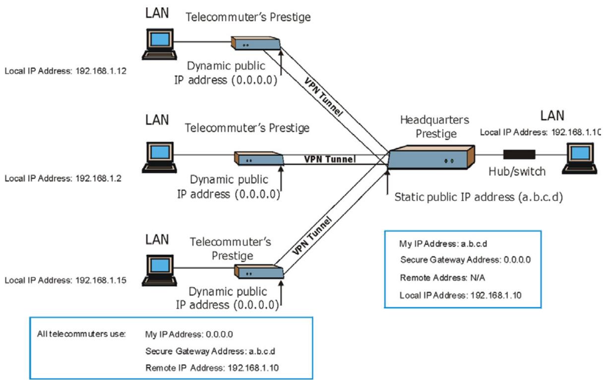
flowchart
graph TD
    subgraph LAN_Portified_Layer
        A1["LAN"] -->|Telecommuter's Prestige| B1["..."]
        B1 -->|VPN Tunnel| C1["Headquarters Prestige"]
        C1 -->|Static public IP address (a.b.c.d)| D1["LAN"]
        A2["LAN"] -->|Telecommuter's Prestige| B2["..."]
        B2 -->|VPN Tunnel| C2["Headquarters Prestige"]
        C2 -->|Static public IP address (a.b.c.d)| D2["LAN"]
        A3["LAN"] -->|Telecommuter's Prestige| B3["..."]
        B3 -->|VPN Tunnel| C3["Headquarters Prestige"]
        C3 -->|Static public IP address (a.b.c.d)| D3["LAN"]
        A4["LAN"] -->|Telecommuter's Prestige| B4["..."]
        B4 -->|VPN Tunnel| C4["Headquarters Prestige"]
        C4 -->|Static public IP address (a.b.c.d)| D4["LAN"]
    end
    style LAN_Portified_Layer fill:#f9f,stroke:#333
    style C1 fill:#ccc,stroke:#333
    style D1 fill:#ccc,stroke:#333
    style D2 fill:#ccc,stroke:#333
    style D3 fill:#ccc,stroke:#333
    style D4 fill:#ccc,stroke:#333
Figure 17-9 Telecommuters Sharing One VPN Rule Example
17.16.2 Telecommuters Using Unique VPN Rules Example
With aggressive negotiation mode (see section 17.10.1), the Prestige can use the ID types and contents to distinguish between VPN rules. Telecommuters can each use a separate VPN rule to simultaneously access a Prestige at headquarters. They can use different IPSec parameters (including the pre-shared key) and the local IP addresses (or ranges of addresses) can overlap.
See the following graphic for an example where three telecommuters each use a different VPN rule to initiate a VPN connection to a Prestige located at headquarters. The Prestige at headquarters identifies each by its ID type and contents and uses the appropriate VPN rule to establish the VPN connection.
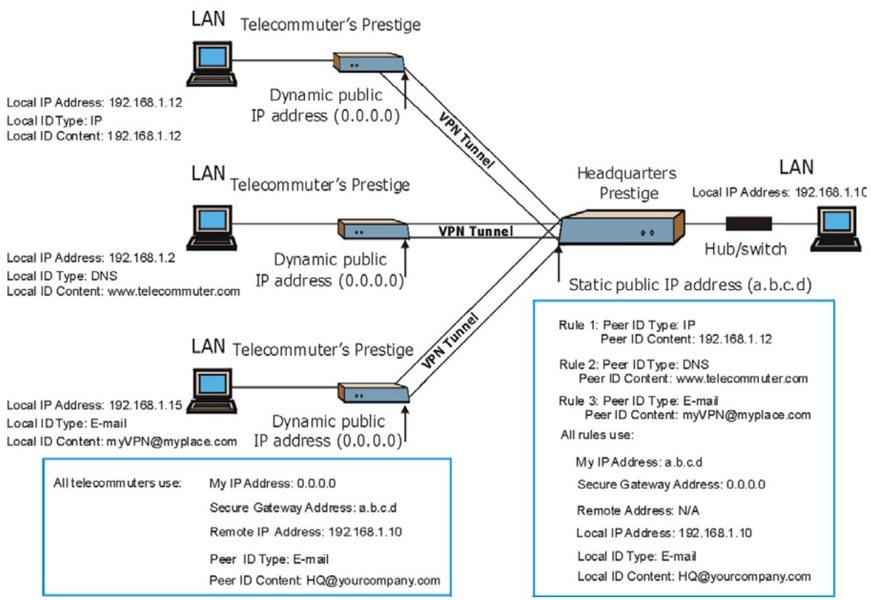
flowchart
graph TD
    A["LAN"] -->|Local IP Address: 192.168.1.12\nLocal ID Type: IP\nLocal ID Content: 192.168.1.12| B["Telecommuter's Prestige"]
    B -->|Dynamic public IP address (0.0.0.0)| C["Headquarters Prestige"]
    C -->|Static public IP address (a.b.c.d)| D["LAN"]
    D -->|Hub/switch| E["Computer"]
    C -->|VPN Tunnel| B
    B -->|VPN Tunnel| C
    style A fill:#f9f,stroke:#333
    style B fill:#bbf,stroke:#333
    style C fill:#dfd,stroke:#333
    style D fill:#dfd,stroke:#333
    style E fill:#dfd,stroke:#333
Figure 17-10 Telecommuters Using Unique VPN Rules Example
17.17VPN and Remote Management
If a VPN tunnel uses a remote management service port (Telnet, FTP, WWW SNMP, DNS or ICMP) and terminates at the Prestige's LAN or WAN port, configure remote management to allow access for that service.
If the VPN tunnel terminates at the Prestige's LAN IP address, configure remote management for LAN or WAN server access (or LAN & WAN or LAN & WAN & DMZ).
If the VPN tunnel terminates at the Prestige's WAN IP address, configure remote management for WAN server access (or LAN & WAN or LAN & WAN & DMZ)
Part VI:
Remote Management, UPnP and Logs
This part contains information on how to configure the Prestige for remote management, setting up Universal Plug and Play (UPnP) and setting up and displaying logs.
Chapter 18
Remote Management Configuration
This chapter provides information on configuring remote management.
18.1 Remote Management Overview
Remote management allows you to determine which services/protocols can access which Prestige interface (if any) from which computers.
When you configure remote management to allow management from the WAN, you still need to configure a firewall rule to allow access. See the firewall chapters for details on configuring firewall rules.
You may manage your Prestige from a remote location via:
▶ Internet (WAN only)
▶ ALL (LAN and WAN)
▶ LAN only,
Neither (Disable).
When you Choose WAN only or ALL (LAN & WAN), you still need to configure a firewall rule to allow access.
To disable remote management of a service, select Disable in the corresponding Server Access field.
18.1.1 Remote Management Limitations
Remote management over LAN or WAN will not work when:
- A filter in SMT menu 3.1 (LAN) or in menu 11.5 (WAN) is applied to block a Telnet, FTP or Web service.
- You have disabled that service in one of the remote management screens.
- The IP address in the Secured Client IP field does not match the client IP address. If it does not match, the Prestige will disconnect the session immediately.
- There is an SMT console session running.
-
There is already another remote management session of the same type (web, FTP or Telnet) running. You may only have one remote management session of the same type running at one time.
-
There is a web remote management session running with a Telnet session. A Telnet session will be disconnected if you begin a web session; it will not begin if there already is a web session.
18.1.2 Remote Management and NAT
When NAT is enabled:
Use the Prestige's WAN IP address when configuring from the WAN.
Use the Prestige's LAN IP address when configuring from the LAN.
18.1.3 System Timeout
There is a system timeout of five minutes (three hundred seconds) for either the console port or telnet/web/FTP connections. Your Prestige automatically logs you out if you do nothing in this timeout period, except when it is continuously updating the status in menu 24.1 or when sys stdio has been changed on the command line.
18.2 Telnet
You can configure your Prestige for remote Telnet access as shown next.
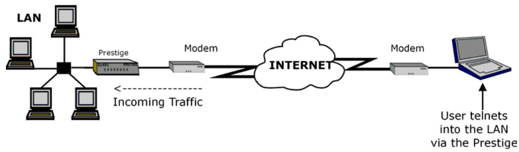
flowchart
graph LR
    A["LAN"] --> B["Prestige"]
    B --> C["Modem"]
    C --> D["INTERNET"]
    D --> E["Modem"]
    E --> F["User telnets into the LAN via the Prestige"]
    style A fill:#f9f,stroke:#333
    style B fill:#ccf,stroke:#333
    style C fill:#cfc,stroke:#333
    style D fill:#fcc,stroke:#333
    style E fill:#cff,stroke:#333
    style F fill:#ffc,stroke:#333
    note1["Incoming Traffic"] -.-> A
Figure 18-1 Telnet Configuration on a TCP/IP Network
18.3 FTP
You can upload and download Prestige firmware and configuration files using FTP. To use this feature, your computer must have an FTP client.
18.4 Web
You can use the Prestige's embedded web configurator for configuration and file management. See the online help for details.
18.5 Configuring Remote Management
Click Remote Management to open the following screen.
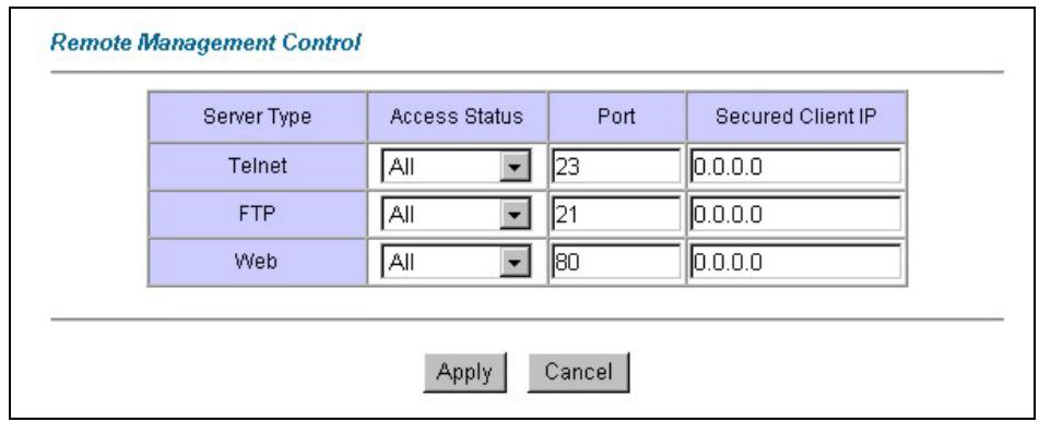
Figure 18-2 Remote Management
The following table describes the fields in this screen.
Table 18-1 Remote Management
| LABEL | DESCRIPTION |
| Server Type | Each of these labels denotes a service that you may use to remotely manage the Prestige. |
| Access Status | Select the access interface. Choices are All, LAN Only, WAN Only and Disable. |
| Port | This field shows the port number for the remote management service. You may change the port number for a service in this field, but you must use the same port number to use that service for remote management. |
| Secured Client IP | The default 0.0.0.0 allows any client to use this service to remotely manage the Prestige. Type an IP address to restrict access to a client with a matching IP address. |
| Apply | Click Apply to save your settings back to the Prestige. |
Table 18-1 Remote Management
| LABEL | DESCRIPTION |
| Cancel | Click Cancel to begin configuring this screen afresh. |
Chapter 19
Universal Plug-and-Play (UPnP)
This chapter introduces the UPnP feature in the web configurator.
19.1 Introducing Universal Plug and Play
Universal Plug and Play (UPnP) is a distributed, open networking standard that uses TCP/IP for simple peer-to-peer network connectivity between devices. A UPnP device can dynamically join a network, obtain an IP address, convey its capabilities and learn about other devices on the network. In turn, a device can leave a network smoothly and automatically when it is no longer in use.
19.1.1 How do I know if I'm using UPnP?
UPnP hardware is identified as an icon in the Network Connections folder (Windows XP). Each UPnP compatible device installed on your network will appear as a separate icon. Selecting the icon of a UPnP device will allow you to access the information and properties of that device.
19.1.2 NAT Traversal
UPnP NAT traversal automates the process of allowing an application to operate through NAT. UPnP network devices can automatically configure network addressing, announce their presence in the network to other UPnP devices and enable exchange of simple product and service descriptions. NAT traversal allows the following:
▶ Dynamic port mapping
▶ Learning public IP addresses
➢ Assigning lease times to mappings
Windows Messenger is an example of an application that supports NAT traversal and UPnP.
See the Network Address Translation (NAT) chapter for further information about NAT.
19.1.3 Cautions with UPnP
The automated nature of NAT traversal applications in establishing their own services and opening firewall ports may present network security issues. Network information and configuration may also be obtained and modified by users in some network environments.
All UPnP-enabled devices may communicate freely with each other without additional configuration. Disable UPnP if this is not your intention.
19.2 UPnP and ZyXEL
ZyXEL has achieved UPnP certification from the Universal Plug and Play Forum Creates UPnPTM Implementers Corp. (UIC). ZyXEL's UPnP implementation supports IGD 1.0 (Internet Gateway Device). At the time of writing ZyXEL's UPnP implementation supports Windows Messenger 4.6 and 4.7 while Windows Messenger 5.0 and Xbox are still being tested.
UPnP broadcasts are only allowed on the LAN.
See later sections for examples of installing UPnP in Windows XP and Windows Me as well as an example of using UPnP in Windows.
19.2.1 Configuring UPnP
From the Site Map in the main menu, click UPnP under Advanced Setup to display the screen shown next.
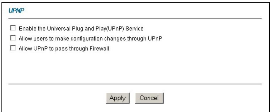
Figure 19-1 Configuring UPnP
The following table describes the fields in this screen.
Table 19-1 Configuring UPnP
| LABEL | DESCRIPTION |
| Enable the Universal Plug and Play (UPnP) Service | Select this checkbox to activate UPnP. Be aware that anyone could use a UPnP application to open the web configurator's login screen without entering the Prestige's IP address (although you must still enter the password to access the web configurator). |
Table 19-1 Configuring UPnP
| LABEL | DESCRIPTION |
| Allow users to make configuration changes through UPnP | Select this check box to allow UPnP-enabled applications to automatically configure the Prestige so that they can communicate through the Prestige, for example by using NAT traversal, UPnP applications automatically reserve a NAT forwarding port in order to communicate with another UPnP enabled device; this eliminates the need to manually configure port forwarding for the UPnP enabled application. |
| Allow UPnP to pass through Firewall | Select this check box to allow traffic from UPnP-enabled applications to bypass the firewall.Clear this check box to have the firewall block all UPnP application packets (for example, MSN packets). |
| Apply | Click Apply to save the setting to the Prestige. |
| Cancel | Click Cancel to return to the previously saved settings. |
19.3 Installing UPnP in Windows Example
This section shows how to install UPnP in Windows Me and Windows XP.
Installing UPnP in Windows Me
Follow the steps below to install the UPnP in Windows Me.
Step 1. Click Start and Control Panel. Double-click Add/Remove Programs.
Step 2. Click on the Windows Setup tab and select Communication in the Components selection box. Click Details.
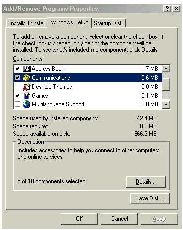
Step 3. In the Communications window, select the Universal Plug and Play check box in the Components selection box.
Step 4. Click OK to go back to the Add/Remove Programs Properties window and click Next.
Step 5. Restart the computer when prompted.
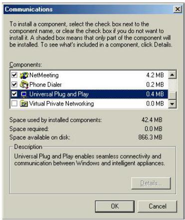
Installing UPnP in Windows XP
Follow the steps below to install the UPnP in Windows XP.
Step 1. Click start and Control Panel.
Step 2. Double-click Network Connections.
Step 3. In the Network Connections window, click Advanced in the main menu and select Optional Networking Components .... The Windows Optional Networking Components Wizard window displays.
Step 4. Select Networking Service in the Components selection box and click Details.
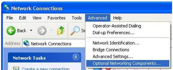
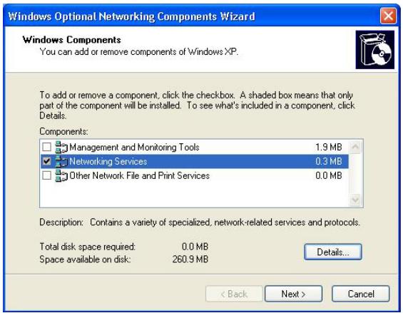
Step 5. In the Networking Services window, select the Universal Plug and Play check box.
Step 6. Click OK to go back to the Windows Optional Networking Component Wizard window and click Next.
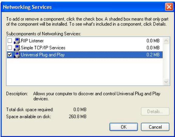
19.4 Using UPnP in Windows XP Example
This section shows you how to use the UPnP feature in Windows XP. You must already have UPnP installed in Windows XP and UPnP activated on the Prestige.
Make sure the computer is connected to a LAN port of the Prestige. Turn on your computer and the Prestige.
Auto-discover Your UPnP-enabled Network Device
Step 1. Click start and Control Panel. Double-click Network Connections. An icon displays under Internet Gateway.
Step 2. Right-click the icon and select Properties.
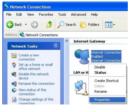
Step 3. In the Internet Connection Properties window, click Settings to see the port mappings there were automatically created.

Step 4. You may edit or delete the port mappings or click Add to manually add port mappings.
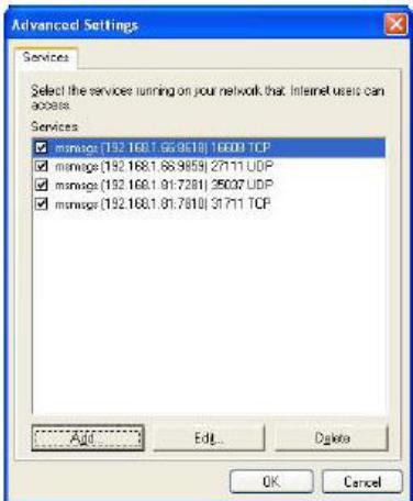
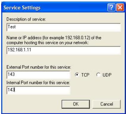
When the UPnP-enabled device is disconnected from your computer, all port mappings will be deleted automatically.
Step 5. Select Show icon in notification area when connected option and click OK. An icon displays in the system tray
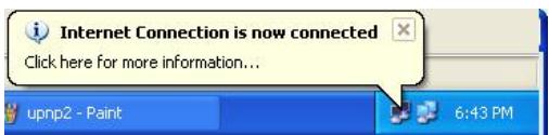
Step 6. Double-click on the icon to display your current Internet connection status.
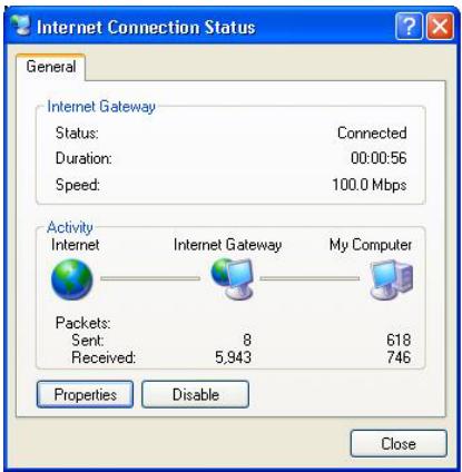
Web Configurator Easy Access
With UPnP, you can access the web-based configurator on the Prestige without finding out the IP address of the Prestige first. This comes helpful if you do not know the IP address of the Prestige.
Follow the steps below to access the web configurator.
Step 1. Click start and then Control Panel.
Step 2. Double-click Network Connections.
Step 3. Select My Network Places under Other Places.
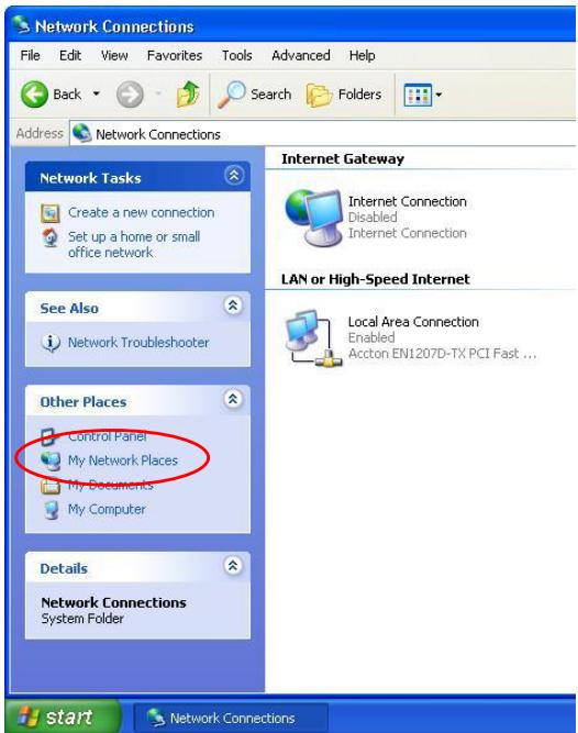
Step 4. An icon with the description for each UPnP-enabled device displays under Local Network.
Step 5. Right-click on the icon for your Prestige and select Invoke. The web configurator login screen displays.
Step 6. Right-click on the icon for your Prestige and select Properties. A properties window displays with basic information about the Prestige.
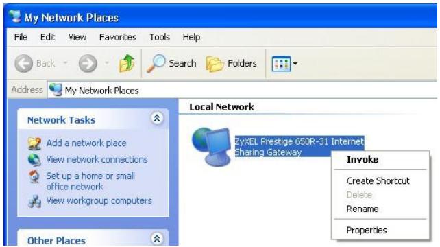
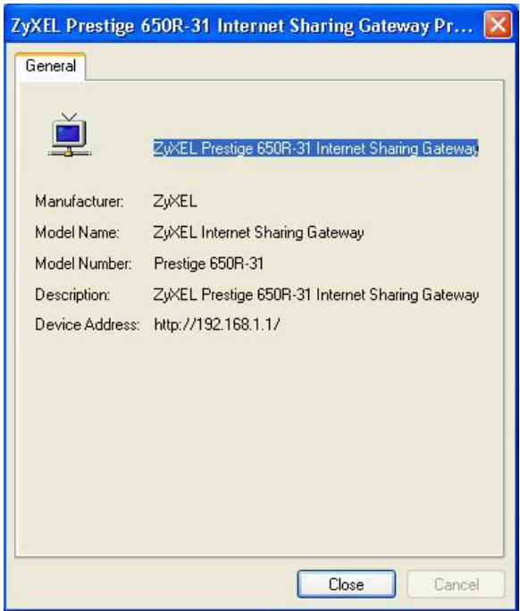
Chapter 20
Logs Screens
This chapter contains information about configuring general log settings and viewing the Prestige's logs. Refer to the appendices for example log message explanations.
20.1 Logs Overview
The web configurator allows you to choose which categories of events and/or alerts to have the Prestige log and then display the logs or have the Prestige send them to an administrator (as e-mail) or to a syslog server.
20.1.1 Alerts and Logs
An alert is a type of log that warrants more serious attention. They include system errors, attacks (access control) and attempted access to blocked web sites. Some categories such as System Errors consist of both logs and alerts. You may differentiate them by their color in the View Log screen. Alerts display in red and logs display in black.
20.2 Configuring Log Settings
Use the Log Settings screen to configure to where the Prestige is to send logs; the schedule for when the Prestige is to send the logs and which logs and/or immediate alerts the Prestige is to record.
To change your Prestige's log settings, click Logs, then the Log Settings. The screen appears as shown.
Logs·Log Settings
Address Info:
Mail Server:
Mail Subject:
Send log to:
Send alerts to:
(Outgoing SMTP Server Name or IP Address)
(E-Mail Address)
(E-Mail Address)
UNIX Syslog:
Active
Syslog IP Address:
Log Facility:
(Server Name or IP Address)
Send Log:
Log Schedule:
Day for Sending Log:
Time for Sending Log:
When Log is Full
Monday
0 (hour): 0 (minute)
Log
□ System Maintenance
□ System Errors
□ Access Control
□ UPnP
Forward Web Sites
□ Blocked Web Sites
□ Attacks
IPSec
□ IKE
Send immediate alert
□ System Errors
□ Blocked Web Sites
□ Attacks

Figure 20-1 Log Settings
The following table describes the fields in this screen.
Table 20-1 Log Settings
| LABEL | DESCRIPTION |
| Address Info | |
| Mail Server | Enter the server name or the IP address of the mail server for the e-mail addresses specified below. If this field is left blank, logs and alert messages will not be sent via e-mail. |
| Mail Subject | Type a title that you want to be in the subject line of the log e-mail message that the Prestige sends. |
| Send log to | Logs are sent to the e-mail address specified in this field. If this field is left blank, logs will not be sent via e-mail. |
| Send alerts to | Alerts are sent to the e-mail address specified in this field. If this field is left blank, alerts will not be sent via e-mail. |
| UNIX Syslog | UNIX syslog sends a log to an external UNIX server used to store logs. |
| Active | Click Active to enable UNIX syslog. |
| Syslog IP Address | Enter the server name or IP address of the syslog server that will log the selected categories of logs. |
| Log Facility | Select a location from the drop down list box. The log facility allows you to log the messages to different files in the syslog server. Refer to your UNIX manual for more information. |
| Send Log | |
| Log Schedule | This drop-down menu is used to configure the frequency of log messages being sent as E-mail:DailyWeeklyHourlyWhen the Log is FullNone.If you select Weekly or Daily, specify a time of day when the E-mail should be sent.If you select Weekly, then also specify which day of the week the E-mail should be sent. If you select When Log is Full, an alert is sent when the log fills up. If you select None, no log messages are sent |
| Day for Sending Log | Use the drop down list box to select which day of the week to send the logs. |
| Time for Sending Log | Enter the time of the day in 24-hour format (for example 23:00 equals 11:00 pm) to send the logs. |
Table 20-1 Log Settings
| LABEL | DESCRIPTION |
| Log | Select the categories of logs that you want to record. Logs include alerts. |
| Send Immediate Alert | Select the categories of alerts for which you want the Prestige to instantly e-mail alerts to the e-mail address specified in theSend Alerts To field. |
| Back | ClickBackto return to the previous screen. |
| Apply | ClickApplyto save your customized settings and exit this screen. |
| Cancel | ClickCancelto return to the previously saved settings. |
20.3 Displaying the Logs
Click Logs and then View Logs to open the View Logs screen. Use the View Logs screen to see the logs for the categories that you selected in the Log Settings screen (see section 20.2).
Log entries in red indicate alerts. The log wraps around and deletes the old entries after it fills. Click a column heading to sort the entries. A triangle indicates ascending or descending sort order.
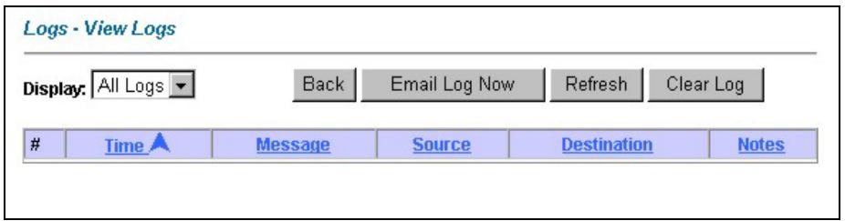
Figure 20-2 View Logs
The following table describes the fields in this screen.
Table 20-2 View Logs
| LABEL | DESCRIPTION |
| Display | The categories that you select in theLog Settingsscreen (see section 20.2) display in the drop-down list box.Select a category of logs to view; selectAll Logsto view logs from all of the log categories that you selected in theLog Settingspage. |
| Time | This field displays the time the log was recorded. See the chapter on system maintenance and information to configure the Prestige’s time and date. |
Table 20-2 View Logs
| LABEL | DESCRIPTION |
| Message | This field states the reason for the log. |
| Source | This field lists the source IP address and the port number of the incoming packet. |
| Destination | This field lists the destination IP address and the port number of the incoming packet. |
| Note | This field displays additional information about the log entry. |
| Back | Click Back to return to the previous screen |
| Email Log Now | Click Email Log Now to send the log screen to the e-mail address specified in the Log Settings page (make sure that you have first filled in the Address Info fields in Log Settings, see section 20.2). |
| Refresh | Click Refresh to renew the log screen. |
| Clear Log | Click Clear Log to delete all the logs. |
20.4 SMTP Error Messages
If there are difficulties in sending e-mail the following error messages appear. Please see the Support Notes on the included disk for information on other types of error messages.
E-mail error messages appear in SMT menu 24.3.1 as "SMTP action request failed. ret=??". The “?” are described in the following table.
Table 20-3 SMTP Error Messages
| -1 means Prestige out of socket |
| -2 means tcp SYN fail |
| -3 means smtp server OK fail |
| -4 means HELO fail |
| -5 means MAIL FROM fail |
| -6 means RCPT TO fail |
| -7 means DATA fail |
| -8 means mail data send fail |
20.4.1 Example E-mail Log
An "End of Log" message displays for each mail in which a complete log has been sent. The following is an example of a log sent by e-mail.
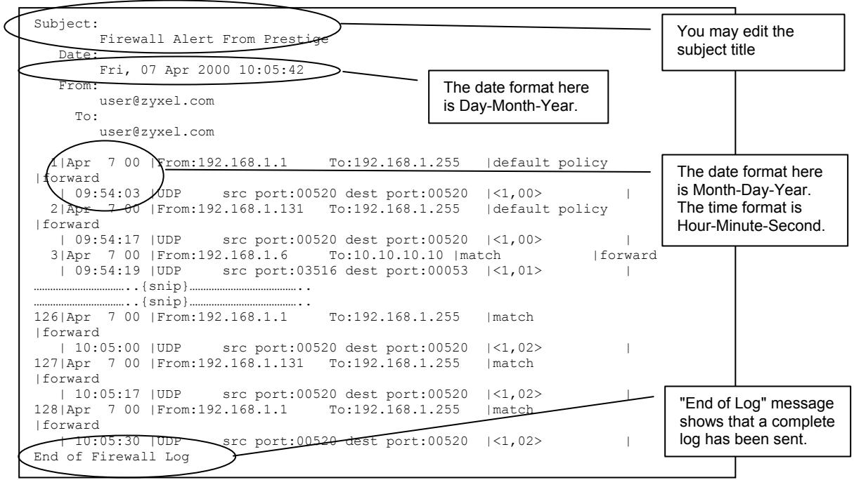
Figure 20-3 E-mail Log Example
Part VII:
Maintenance
This part covers the maintenance screens.
Chapter 21
Maintenance
This chapter displays system information such as ZyNOS firmware, port IP addresses and port traffic statistics.
21.1 Maintenance Overview
The maintenance screens can help you view system information, upload new firmware, manage configuration and restart your Prestige.
21.2 System Status Screen
Click System Status to open the following screen, where you can use to monitor your Prestige. Note that these fields are READ-ONLY and are meant to be used for diagnostic purposes.
System Status
System Status
System Name : ZyNOS FW Version: V3.40(IU.0)b6 | 4/8/2003 DSL FW Version: Alcatel, Version 3.9.122 Standard: Multi-Mode
WAN Information:
IP Address: 0.0.0.0 IP Subnet Mask: 0.0.0.0 Default Gateway: 0.0.0.0 VPI/VCI: 0/35
LAN Information:
MAC Address: 00:a0:c5:46:99:91 IP Address: 192.168.1.1 IP Subnet Mask: 255.255.255.0 DHCP: Server DHCP Start IP: 192.168.1.33 DHCP Pool Size: 32
Show Statistics
Figure 21-1 System Status
The following table describes the fields in this screen.
Table 21-1 System Status
| LABEL | DESCRIPTION |
| System Status | |
Table 21-1 System Status
| LABEL | DESCRIPTION |
| System Name | This is the name of your Prestige. It is for identification purposes. |
| ZyNOS Firmware Version | This is the ZyNOS firmware version and the date created. ZyNOS is ZyXEL's proprietary Network Operating System design. |
| DSL FW Version | This is the DSL firmware version associated with your Prestige. |
| Standard | This is the standard that your Prestige is using. |
| WAN Information | |
| IP Address | This is the WAN port IP address. |
| IP Subnet Mask | This is the WAN port IP subnet mask. |
| Default Gateway | This is the IP address of the default gateway, if applicable. |
| VPI/VCI | This is the Virtual Path Identifier and Virtual Channel Identifier that you entered in the first Wizard screen. |
| LAN Information | |
| MAC Address | This is the MAC (Media Access Control) or Ethernet address unique to your Prestige. |
| IP Address | This is the LAN port IP address. |
| IP Subnet Mask | This is the LAN port IP subnet mask. |
| DHCP | This is the WAN port DHCP role - Server, Relay (not all Prestige models) or None. |
| DHCP Start IP | This is the first of the contiguous addresses in the IP address pool. |
| DHCP Pool Size | This is the number of IP addresses in the IP address pool. |
| Show Statistics | Click Show Statistics to see router performance statistics such as number of packets sent and number of packets received for each port. |
21.2.1 System Statistics
Click Show Statistics in the System Status screen to open the following screen. Read-only information here includes port status and packet specific statistics. Also provided are "system up time" and "poll interval(s)". The Poll Interval(s) field is configurable.
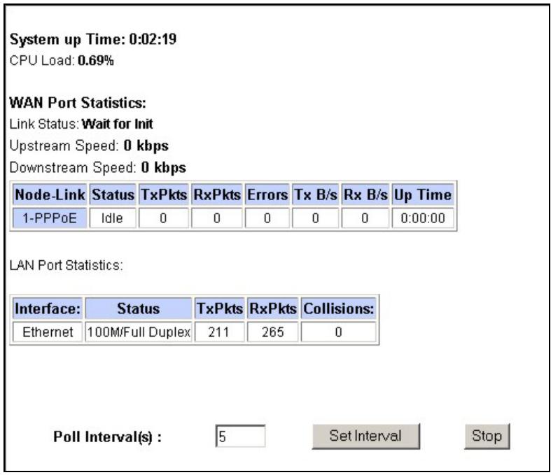
Figure 21-2 System Status: Show Statistics
The following table describes the fields in this screen.
Table 21-2 System Status: Show Statistics
| LABEL | DESCRIPTION |
| System up Time | This is the elapsed time the system has been up. |
| CPU Load | This field specifies the percentage of CPU utilization. |
| LAN or WAN Port Statistics | This is the WAN or LAN port. |
| Link Status | This is the status of your WAN link. |
Table 21-2 System Status: Show Statistics
| LABEL | DESCRIPTION |
| Transfer Rate | This is the transfer rate in kbps. |
| Upstream Speed | This is the upstream speed of your Prestige. |
| Downstream Speed | This is the downstream speed of your Prestige. |
| Node-Link | This field displays the remote node index number and link type. Link types are PPPoA, ENET, RFC 1483 and PPPoE . |
| Interface | This field displays the type of port. |
| Status | For the WAN port, this displays the port speed and duplex setting if you're using Ethernet encapsulation and down (line is down), idle (line (ppp) idle), dial (starting to trigger a call) and drop (dropping a call) if you're using PPPoE encapsulation.For a LAN port, this shows the port speed and duplex setting. |
| TxPkts | This field displays the number of packets transmitted on this port. |
| RxPkts | This field displays the number of packets received on this port. |
| Errors | This field displays the number of error packets on this port. |
| Tx B/s | This field displays the number of bytes transmitted in the last second. |
| Rx B/s | This field displays the number of bytes received in the last second. |
| Up Time | This field displays the elapsed time this port has been up. |
| Collisions | This is the number of collisions on this port. |
| Poll Interval(s) | Type the time interval for the browser to refresh system statistics. |
| Set Interval | Click this button to apply the new poll interval you entered in the Poll Interval field above. |
| Stop | Click this button to halt the refreshing of the system statistics. |
21.3 DHCP Table Screen
DHCP (Dynamic Host Configuration Protocol, RFC 2131 and RFC 2132) allows individual clients to obtain TCP/IP configuration at start-up from a server. You can configure the Prestige as a DHCP server or disable it. When configured as a server, the Prestige provides the TCP/IP configuration for the clients. If set to None, DHCP service will be disabled and you must have another DHCP server on your LAN, or else the computer must be manually configured.
Click MAINTENANCE, and then the DHCP Table tab. Read-only information here relates to your DHCP status. The DHCP table shows current DHCP Client information (including IP Address, Host Name and MAC Address) of all network clients using the DHCP server.
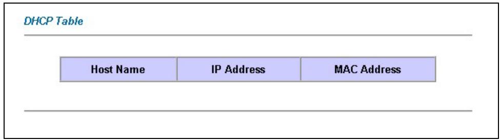
Figure 21-3 DHCP Table
The following table describes the fields in this screen.
Table 21-3 DHCP Table
| LABEL | DESCRIPTION |
| Host Name | This is the name of the host computer. |
| IP Address | This field displays the IP address relative to the Host Name field. |
| MAC Address | This field displays the MAC (Media Access Control) address of the computer with the displayed host name.Every Ethernet device has a unique MAC address. The MAC address is assigned at the factory and consists of six pairs of hexadecimal characters, for example, 00:A0:C5:00:00:02. |
21.4 Wireless Screens
These read-only screens display information about the Prestige's wireless LAN.
21.4.1 Association List
This screen displays the MAC address(es) of the wireless clients that are currently logged in to the network. Click Wireless LAN and then Association List to open the screen shown next.
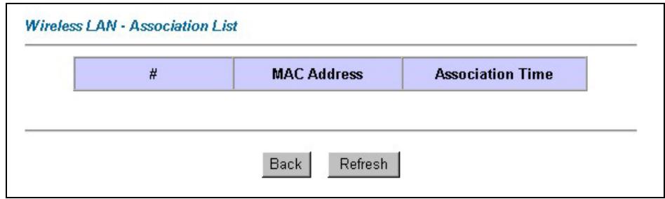
Figure 21-4 Association List
The following table describes the fields in this screen.
Table 21-4 Association List
| LABEL | DESCRIPTION |
| # | This is the index number of an associated wireless client. |
| MAC Address | This field displays the MAC (Media Access Control) address of an associated wireless client. Every Ethernet device has a unique MAC address. The MAC address is assigned at the factory and consists of six pairs of hexadecimal characters, for example, 00:A0:C5:00:00:02. |
| Association Time | This field displays how long a wireless client has been associated to the Prestige. |
| Back | Click Back to return to the previous screen. |
| Refresh | Click Refresh to renew the information in the table. |
21.4.2 Channel Usage Table
This screen displays the state of the channels within the Prestige's transmission range. Click Wireless LAN and then Channel Usage Table to open the screen shown next.
Wireless LAN · Channel Usage Table
| Channel | Activity |
| 1 | Yes |
| 2 | Yes |
| 3 | Yes |
| 4 | Yes |
| 5 | Yes |
| 6 | Yes |
| 7 | Yes |
| 8 | No |
| 9 | No |
| 10 | No |
| 11 | Yes |
Back
Refresh
Figure 21-5 Channel Usage Table
The following table describes the fields in this screen.
Table 21-5 Channel Usage Table
| LABEL | DESCRIPTION |
| Channel | This is the index number of the channel. |
| IP Address | This field displays Yes if another AP or Ad-hoc network is using the channel within the Prestige's transmission range. |
| Back | Click Back to return to the previous screen. |
| Refresh | Click Refresh to renew the information in the table. |
21.5 Diagnostic Screens
These read-only screens display information to help you identify problems with the Prestige.
21.5.1 Diagnostic General Screen
Click Diagnostic and then General to open the screen shown next.
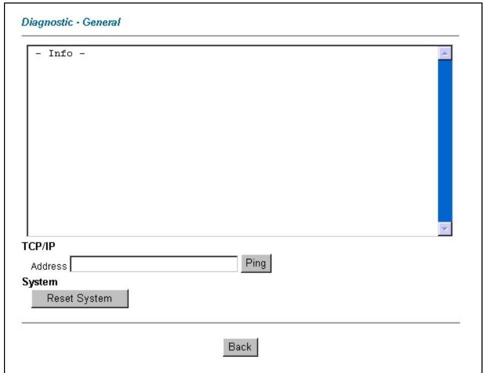
Figure 21-6 Diagnostic General
The following table describes the fields in this screen.
Table 21-6 Diagnostic General
| LABEL | DESCRIPTION |
| TCP/IP Address | Type the IP address of a computer that you want to ping in order to test a connection. |
| Ping | Click this button to ping the IP address that you entered. |
| Reset System | Click this button to reboot the Prestige. A warning dialog box is then displayed asking you if you're sure you want to reboot the system. Click OK to proceed. |
| Back | Click this button to go back to the main Diagnostic screen. |
21.5.2 Diagnostic DSL Line Screen
Click Diagnostic and then DSL Line to open the screen shown next.
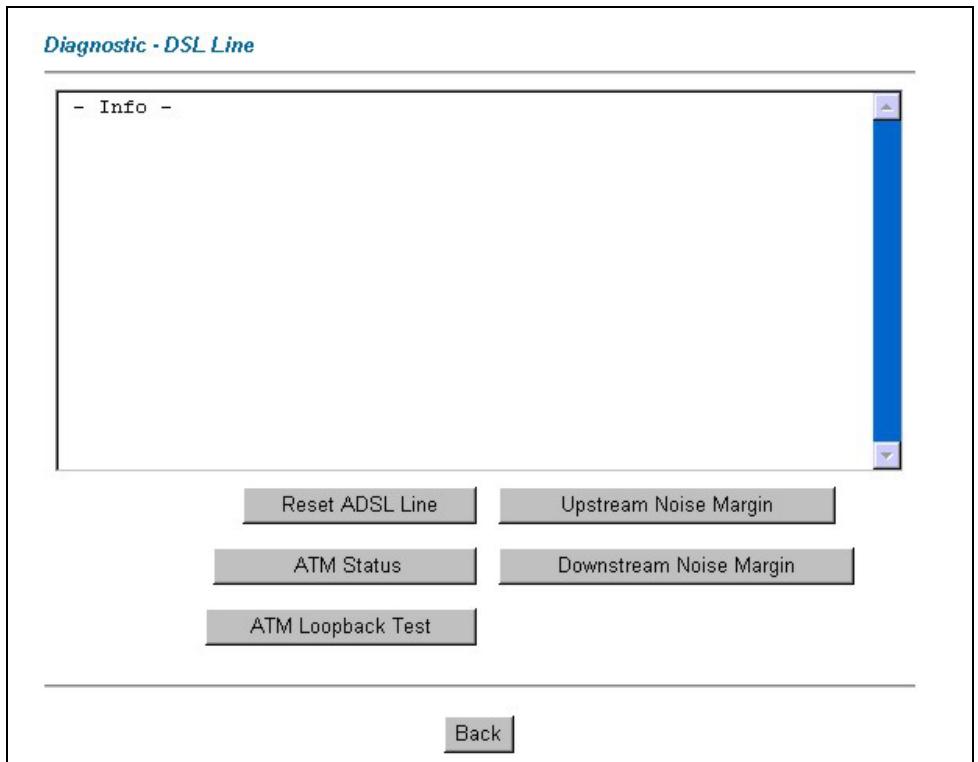
Figure 21-7 Diagnostic DSL Line
The following table describes the fields in this screen.
Table 21-7 Diagnostic DSL Line
| LABEL | DESCRIPTION |
| Reset ADSL Line | Click this button to reinitialize the ADSL line. The large text box above then displays the progress and results of this operation, for example:"Start to reset ADSLLoading ADSL modem F/W...Reset ADSL Line Successfully!" |
| ATM Status | Click this button to view ATM status. |
Table 21-7 Diagnostic DSL Line
| LABEL | DESCRIPTION |
| ATM Loopback Test | Click this button to start the ATM loopback test. Make sure you have configured at least one PVC with proper VPIs/VCIs before you begin this test. The Prestige sends an OAM F5 packet to the DSLAM/ATM switch and then returns it (loops it back) to the Prestige. The ATM loopback test is useful for troubleshooting problems with the DSLAM and ATM network. |
| Upstream Noise Margin | Click this button to display the upstream noise margin. |
| Downstream Noise Margin | Click this button to display the downstream noise margin. |
| Back | Click this button to go back to the main Diagnostic screen. |
21.6 Firmware Screen
Find firmware at www.zyxel.com in a file that (usually) uses the system model name with a "*.bin" extension, e.g., "Prestige.bin". The upload process uses FTP (File Transfer Protocol) and may take up to two minutes. After a successful upload, the system will reboot. See the Firmware and Configuration File Maintenance chapter in the parts that document the SMT for upgrading firmware using FTP/TFTP commands.
Only use firmware for your device's specific model. Refer to the label on the bottom of your device.
Click Firmware to open the following screen. Follow the instructions in this screen to upload firmware to your Prestige.
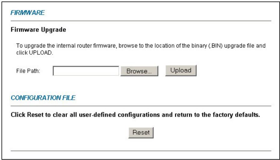
Figure 21-8 Firmware Upgrade
The following table describes the fields in this screen.
Table 21-8 Firmware Upgrade
| LABEL | DESCRIPTION |
| File Path | Type in the location of the file you want to upload in this field or click Browse ... to find it. |
| Browse... | Click Browse... to find the .bin file you want to upload. Remember that you must decompress compressed (.zip) files before you can upload them. |
| Upload | Click Upload to begin the upload process. This process may take up to two minutes. |
| Reset | Click this button to clear all user-entered configuration information and return the Prestige to its factory defaults. |
Do not turn off the device while firmware upload is in progress!
After you see the Firmware Upload in Process screen, wait two minutes before logging into the device again.
The device automatically restarts in this time causing a temporary network disconnect. In some operating systems, you may see the following icon on your desktop.
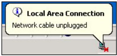
Figure 21-9 Network Temporarily Disconnected
After two minutes, log in again and check your new firmware version in the System Status screen.
If the upload was not successful, the following screen will appear. Click Back to go back to the Firmware screen.
Error Message:
ERROR: FAIL TO UPDATE DUE TO... The uploaded file was not accepted by the router.
Back
Figure 21-10 Error Message
Part VIII:
SMT General Configuration
This part covers System Management Terminal configuration for general setup, WAN backup, LAN setup, wireless LAN setup, Internet access, remote node, static route, NAT and enabling the firewall.
See the web configurator parts of this guide for background information on features configurable by web configurator and SMT.
Chapter 22
Introducing the SMT
This chapter explains how to access and navigate the System Management Terminal and gives an overview of its menus.
22.1 SMT Introduction
The Prestige's SMT (System Management Terminal) is a menu-driven interface that you can access from a terminal emulator through the console port or over a telnet connection. This chapter shows you how to access the SMT (System Management Terminal) menus via console port, how to navigate the SMT and how to configure SMT menus.
22.1.1 Procedure for SMT Configuration via Console Port
Follow the steps below to access your Prestige via the console port.
Configure a terminal emulation communications program as follows: VT100 terminal emulation, no parity, 8 data bits, 1 stop bit, data flow set to none, 9600 bps port speed.
Press [ENTER] to display the SMT password screen. The default password is “1234”.
22.1.2 Procedure for SMT Configuration via Telnet
The following procedure details how to telnet into your Prestige.
Step 1. In Windows, click Start (usually in the bottom left corner), Run and then type “telnet 192.168.1.1” (the default IP address) and click OK.
Step 2. Enter "1234" in the Password field.
Step 3. After entering the password you will see the main menu.
Please note that if there is no activity for longer than five minutes (default timeout period) after you log in, your Prestige will automatically log you out. You will then have to telnet into the Prestige again.
22.1.3 Entering Password
The login screen appears after you press [ENTER], prompting you to enter the password, as shown next.
For your first login, enter the default password “1234”. As you type the password, the screen displays an asterisk “*” for each character you type.
Please note that if there is no activity for longer than five minutes after you log in, your Prestige will automatically log you out.
Enter Password : ****
Figure 22-1 Login Screen
22.1.4 Prestige SMT Menu Overview
We use the Prestige 652HW-31 SMT menus in this guide as an example. The SMT menus vary slightly for different Prestige models.
The following figure gives you an overview of the various SMT menu screens of your Prestige.
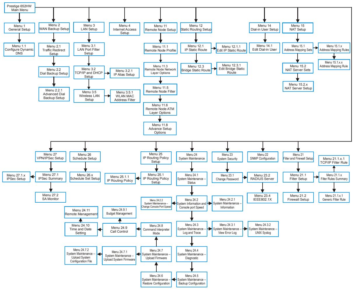
flowchart
graph TD
    A["Prestige 652HW Main Menu"] --> B["Menu 1 General Setup"]
    B --> C["Menu 1.1 Configure Dynamic DNS"]
    C --> D["Menu 2.1 Traffic Redirect Setup"]
    D --> E["Menu 2.2 Dial Backup Setup"]
    E --> F["Menu 2.2.1 Advanced Dial Backup Setup"]
    F --> G["Menu 27.1x IPSec Setup"]
    G --> H["Menu 27.2 SA Monitor"]
    H --> I["Menu 24.11 Remote Management"]
    I --> J["Menu 24.10 Time and Date Setting"]
    J --> K["Menu 24.9 Call Control"]
    K --> L["Menu 24.8 Command Interpreter Mode"]
    L --> M["Menu 24.7 System Maintenance -- Upload System Firmware"]
    M --> N["Menu 24.7.1 System Maintenance -- Upload System Configuration File"]
    N --> O["Menu 24.6 System Maintenance -- Restore Configuration"]
    O --> P["Menu 24.5 System Maintenance -- Backup Configuration"]

    A --> Q["Menu 2 WAN Backup Setup"]
    Q --> R["Menu 3.1 LAN Setup"]
    R --> S["Menu 3.1 LAN Port Filter Setup"]
    S --> T["Menu 3.2 TCP/IP and DHCP Setup"]
    T --> U["Menu 3.2.1 IP Alias Setup"]
    U --> V["Menu 3.5 Wireless LAN Setup"]
    V --> W["Menu 3.5.1 WLAN MAC Address Filter"]

    A --> X["Menu 11 Remote Node Setup"]
    X --> Y["Menu 11.1 Remote Node Profile"]
    Y --> Z["Menu 11.3 Remote Node Network Layer Options"]
    Z --> AA["Menu 11.5 Remote Node Filter"]
    AA --> AB["Menu 11.6 Remote Node ATM Layer Options"]
    AB --> AC["Menu 11.8 Advance Setup Options"]

    A --> AD["Menu 12 Static Routing Setup"]
    AD --> AE["Menu 12.1 IP Static Route"]
    AE --> AF["Menu 12.3 Bridge Static Route"]
    AF --> AG["Menu 12.3.1 Edit Bridge Static Route"]

    A --> AH["Menu 14 Dial-in User Setup"]
    AH --> AI["Menu 14.1 Edit Dial-in User"]
    AI --> AJ["Menu 15.1 Address Mapping Sets"]
    AJ --> AK["Menu 15.2 NAT Server Sets"]
    AK --> AL["Menu 15.2.x NAT Server Setup"]

    A --> AM["Menu 15 NAT Setup"]
    AM --> AN["Menu 15.1.x Address Mapping Rules"]

    B --> AO["Menu 26 Schedule Setup"]
    AO --> AP["Menu 26.x Schedule Set Setup"]
    AP --> AQ["Menu 25.1 IP Routing Policy Setup"]
    AQ --> AR["Menu 25 IP Routing Policy Setup"]
    AR --> AS["Menu 24 System Maintenance"]
    AS --> AT["Menu 24 System Maintenance -- Status"]
    AT --> AU["Menu 24.1 System Maintenance -- Change Console Port Speed"]
    AU --> AV["Menu 24.2 System Information and Console port Speed"]
    AV --> AW["Menu 24.2.1 System Maintenance -- Information"]

    C --> AX["Menu 27 VPN/IPSec Setup"]
    AX --> AY["Menu 27.1 IPSec Summary"]

    D --> AZ["Menu 23 System Security"]
    AZ --> BA["Menu 23.1 Change Password"]
    BA --> BB["Menu 23.2 RADIUS Server"]
    BB --> BC["Menu 23.4 IEEE802.1X"]

    E --> BD["Menu 22 SNMP Configuration"]
    BD --> BE["Menu 21 Filter and Firewall Setup"]

    AF --> BF["Menu 21.1 x TCP/IP Filter Rule"]
    BF --> BG["Menu 21.1 x Filter Rules Summary"]

    G --> BH["Menu 27.1.x IPSec Setup"]
    BH --> BI["Menu 27.2 SA Monitor"]

    I --> BJ["Menu 24.9 Budget Management"]
    BJ --> BK["Menu 24.8 Command Interpreter Mode"]
    BK --> BL["Menu 24.7 System Maintenance -- Log and Trace"]
    BL --> BM["Menu 24.4 System Maintenance -- Diagnostic"]

    AK --> BN["Menu 24.3 System Maintenance -- View Error Log"]
    BN --> BO["Menu 24.3.1 System Maintenance -- UNIX Syslog"]

    AL --> BP["Menu 24.6 System Maintenance -- Restore Configuration"]
    BP --> BQ["Menu 24.5 System Maintenance -- Backup Configuration"]
Figure 22-2 Prestige 652HW-31 SMT Menu Overview
22.2 Navigating the SMT Interface
The SMT (System Management Terminal) is the interface that you use to configure your Prestige.
Several operations that you should be familiar with before you attempt to modify the configuration are listed in the table below.
Table 22-1 Main Menu Commands
| OPERATION | KEYSTROKE | DESCRIPTION |
| Move down to another menu | [ENTER] | To move forward to a submenu, type in the number of the desired submenu and press [ENTER]. |
| Move up to a previous menu | [ESC] | Press [ESC] to move back to the previous menu. |
| Move to a “hidden” menu | Press [SPACE BAR] to change No to Yes then press [ENTER]. | Fields beginning with “Edit” lead to hidden menus and have a default setting of No. Press [SPACE BAR] once to change No to Yes, then press [ENTER] to go to the “hidden” menu. |
| Move the cursor | [ENTER] or [UP]/[DOWN] arrow keys. | Within a menu, press [ENTER] to move to the next field. You can also use the [UP]/[DOWN] arrow keys to move to the previous and the next field, respectively. |
| Entering information | Type in or press [SPACE BAR], then press [ENTER]. | You need to fill in two types of fields. The first requires you to type in the appropriate information. The second allows you to cycle through the available choices by pressing [SPACE BAR]. |
| Required fields | <?> or ChangeMe | All fields with the symbol <?> must be filled in order to be able to save the new configuration.All fields with ChangeMe must not be left blank in order to be able to save the new configuration. |
| N/A fields | Some of the fields in the SMT will show a. This symbol refers to an option that is Not Applicable. | |
| Save your configuration | [ENTER] | Save your configuration by pressing [ENTER] at the message “Press ENTER to confirm or ESC to cancel”. Saving the data on the screen will take you, in most cases to the previous menu. |
| Exit the SMT | Type 99, then press [ENTER]. | Type 99 at the main menu prompt and press [ENTER] to exit the SMT interface. |
After you enter the password, the SMT displays the main menu, as shown next.
| Copyright (c) 1994 - 2003 ZyXEL Communications Corp. | |
| Prestige 652HW-31 Main Menu | |
| Getting Started | Advanced Management |
| 1. General Setup | 21. Filter and Firewall Setup |
| 2, WAN Backup Setup | 22. SNMP Configuration |
| 3. LAN Setup | 23. System Security |
| 4. Internet Access Setup | 24. System Maintenance |
| 25. IP Routing Policy Setup | |
| 26. Schedule Setup | |
| Advanced Applications | 27. VPN/IPSec Setup |
| 11. Remote Node Setup | |
| 12. Static Routing Setup | 99. Exit |
| 14. Dial-in User Setup | |
| 15. NAT Setup | |
| Enter Menu Selection Number:_ | |
Figure 22-3 SMT Main Menu
22.2.1 System Management Terminal Interface Summary
Table 22-2 Main Menu Summary
| # | MENU TITLE | DESCRIPTION |
| 1 | General Setup | Use this menu to set up your general information. |
| 2 | WAN Backup Setup | Use this menu to setup traffic redirect and dial-back up. |
| 3 | LAN Setup | Use this menu to set up your wireless LAN (Prestige 652H/HW only) and LAN connection. |
| 4 | Internet Access Setup | A quick and easy way to set up an Internet connection. |
| 11 | Remote Node Setup | Use this menu to set up the Remote Node for LAN-to-LAN connection, including Internet connection. |
| 12 | Static Routing Setup | Use this menu to set up static routes. |
| 14 | Dial-in User Setup | Use this menu to set up local user profiles on the Prestige 652H/HW. |
| 15 | NAT Setup | Use this menu to specify inside servers when NAT is enabled. |
| 21 | Filter and Firewall Setup | Use this menu to configure filters, activate/deactivate the firewall and view the firewall log. |
| 22 | SNMP Configuration | Use this menu to set up SNMP related parameters. |
Table 22-2 Main Menu Summary
| # | MENU TITLE | DESCRIPTION |
| 23 | System Security | Use this menu to set up wireless security (Prestige 652H/HW only) and change your password. |
| 24 | System Maintenance | This menu provides system status, diagnostics, software upload, etc. |
| 25 | IP Routing Policy Setup | Use this menu to configure your IP routing policy. |
| 26 | Schedule Setup | Use this menu to schedule outgoing calls. |
| 27 | VPN/ IPSec Setup | Use this menu to configure VPN connections. |
| 99 | Exit | Use this to exit from SMT and return to a blank screen. |
22.3 Changing the System Password
Change the Prestige default password by following the steps shown next.
Step 1. Enter 23 in the main menu to display Menu 23 - System Security.
Step 2. Enter 1 to display Menu 23.1 - System Security - Change Password as shown next.
Step 3. Type your existing system password in the Old Password field, for example “1234”, and press [ENTER].
Menu 23.1 - System Security - Change Password
Old Password= ?
New Password= ?
Retype to confirm= ?
Enter here to CONFIRM or ESC to CANCEL:
Figure 22-4 Menu 23 System Password
Step 4. Type your new system password in the New Password field (up to 30 characters), and press [ENTER].
Step 5. Re-type your new system password in the Retype to confirm field for confirmation and press [ENTER].
Note that as you type a password, the screen displays an “*” for each character you type.
Chapter 23
Menu 1 General Setup
Menu 1 - General Setup contains administrative and system-related information.
23.1 General Setup
Menu 1 — General Setup contains administrative and system-related information (shown next). The System Name field is for identification purposes. However, because some ISPs check this name you should enter your computer's "Computer Name".
- In Windows 95/98 click Start, Settings, Control Panel, Network. Click the Identification tab, note the entry for the Computer name field and enter it as the Prestige System Name.
- In Windows 2000 click Start, Settings, Control Panel and then double-click System. Click the Network Identification tab and then the Properties button. Note the entry for the Computer name field and enter it as the Prestige System Name.
- In Windows XP, click start, My Computer, View system information and then click the Computer Name tab. Note the entry in the Full computer name field and enter it as the Prestige System Name.
The Domain Name entry is what is propagated to the DHCP clients on the LAN. If you leave this blank, the domain name obtained by DHCP from the ISP is used. While you must enter the host name (System Name) on each individual computer, the domain name can be assigned from the Prestige via DHCP.
23.2 Procedure To Configure Menu 1
Step 1. Enter 1 in the Main Menu to open Menu 1 — General Setup (shown next).
Menu 1 - General Setup
System Name= ?
Location=
Contact Person's Name=
Domain Name=
Edit Dynamic DNS= No
Route IP= Yes
Bridge= No
Press ENTER to Confirm or ESC to Cancel:
Figure 23-1 Menu 1 General Setup
Step 2. Fill in the required fields. Refer to the table shown next for more information about these fields.
Table 23-1 Menu 1 General Setup
| FIELD | DESCRIPTION | EXAMPLE |
| System Name | Choose a descriptive name for identification purposes. This name can be up to 30 alphanumeric characters long. Spaces are not allowed, but dashes “-” and underscores ”_” are accepted. | P652HW |
| Location (optional) | Enter the geographic location (up to 31 characters) of your Prestige. | MyHouse |
| Contact Person's Name (optional) | Enter the name (up to 30 characters) of the person in charge of this Prestige. | JohnDoe |
| Domain Name | Enter the domain name (if you know it) here. If you leave this field blank, the ISP may assign a domain name via DHCP. You can go to menu 24.8 and type "sys domainname" to see the current domain name used by your gateway.If you want to clear this field just press the [SPACE BAR]. The domain name entered by you is given priority over the ISP assigned domain name. | zyxel.com.tw |
| Edit Dynamic DNS | Press the [SPACE BAR] to select Yes or No (default). Select Yes to configure Menu 1.1 — Configure Dynamic DNS (discussed next). | No |
| Route IP | Set this field to Yes to enable or No to disable IP routing. You must enable IP routing for Internet access. | Yes |
| Bridge | Turn on/off bridging for protocols not supported (for example, SNA) or not turned on in the previous Route IP field. Select Yes to turn bridging on; select No to turn bridging off. | No |
23.2.1 Procedure to Configure Dynamic DNS
If you have a private WAN IP address, then you cannot use Dynamic DNS.
Step 1. To configure Dynamic DNS, go to Menu 1 — General Setup and select Yes in the Edit Dynamic DNS field. Press [ENTER] to display Menu 1.1— Configure Dynamic DNS as shown next.
Menu 1.1 - Configure Dynamic DNS
Service Provider = WWW.DynDNS.ORG
Active= Yes
Host= me.ddns.org
EMAIL= mail@mailserver
USER= username
Password= *****
Enable Wildcard= No
Press ENTER to confirm or ESC to cancel:
Figure 23-2 Menu 1.1 Configure Dynamic DNS
Follow the instructions in the next table to configure Dynamic DNS parameters.
Table 23-2 Menu 1.1 Configure Dynamic DNS
| FIELD | DESCRIPTION | EXAMPLE |
| Service Provider | This is the name of your Dynamic DNS service provider. | WWW.DynDNS.ORG (default) |
| Active | Press [SPACE BAR] to select Yes and then press [ENTER] to make dynamic DNS active. | Yes |
| Host | Enter the domain name assigned to your Prestige by your Dynamic DNS provider. | me.dyndns.org |
| Enter your e-mail address. | mail@mailserver | |
| USER | Enter your user name. | |
| Password | Enter the password assigned to you. | |
| Enable Wildcard | Your Prestige supports DYNDNS Wildcard. Press [SPACE BAR] and then [ENTER] to select Yes or No This field is N/A when you choose DDNS client as your service provider. | No |
| When you have completed this menu, press [ENTER] at the prompt “Press ENTER to Confirm...” to save your configuration, or press [ESC] at any time to cancel. | ||
Chapter 24
Menu 2 WAN Backup Setup
This chapter describes how to configure traffic redirect and dial-backup using menu 2, 2.1, 2.2
and 2.2.1.
24.1 Introduction to WAN Backup Setup
This chapter explains how to configure the Prestige for traffic redirect and dial backup connections.
24.2 Dial Backup
To set up the auxiliary port (DIAL BACKUP on the Prestige 652 or AUX on the Prestige 652H/HW) for use in the event that the regular WAN connection is dropped, first make sure you have set up the port connection (and the CON/AUX switch to AUX on the Prestige 652H/HW) and then configure:
- Menu 2 - WAN Backup Setup
- Menu 2.2 – Dial Backup Setup
- Menu 2.2.1 - Advanced Dial Backup Setup
- Menu 11.1 - Remote Node Profile
Refer also to the traffic redirect section for information on an alternate backup WAN connection.
24.3 Configuring Dial Backup in Menu 2
From the main menu, enter 2 to open menu 2.
| Menu 2 - Wan Backup Setup |
| Check Mechanism = DSL Link Check WAN IP Address1 = 0.0.0.0 Check WAN IP Address2 = 0.0.0.0 Check WAN IP Address3 = 0.0.0.0 KeepAlive Fail Tolerance = 0 Recovery Interval(sec) = 0 ICMP Timeout(sec) = 0 Traffic Redirect = No Dial Backup = No |
| Press ENTER to Confirm or ESC to Cancel: |
| Press Space Bar to Toggle. |
Figure 24-1 Menu 2 WAN Backup Setup
The following table describes the fields in this menu.
Table 24-1 Menu 2 WAN Backup Setup
| FIELD | DESCRIPTION |
| Check Mechanism | Press [SPACE BAR] and then press [ENTER] to select the method that the Prestige uses to check the DSL connection.SelectDSL Linkto have the Prestige check the DSL connection’s physical layer. SelectICMPto have the Prestige periodically ping the IP addresses configured in theCheck WAN IP Addressfields. |
| Check WAN IP Address1-3 | Configure this field to test your Prestige's WAN accessibility. Type the IP address of a reliable nearby computer (for example, your ISP's DNS server address).When using a WAN backup connection, the Prestige periodically pings the addresses configured here and uses the other WAN backup connection (if configured) if there is no response. |
| KeepAlive Fail Tolerance | Type the number of times (2 recommended) that your Prestige may ping the IP addresses configured in theCheck WAN IP Addressfield without getting a response before switching to a WAN backup connection (or a different WAN backup connection). |
Table 24-1 Menu 2 WAN Backup Setup
| FIELD | DESCRIPTION |
| Recovery Interval(sec) | When the Prestige is using a lower priority connection (usually a WAN backup connection), it periodically checks to whether or not it can use a higher priority connection.Type the number of seconds (30 recommended) for the Prestige to wait between checks. Allow more time if your destination IP address handles lots of traffic. |
| Traffic Redirect | Press [SPACE BAR] to select Yes or No.Select Yes and press [ENTER] to configure Menu 2.1 Traffic Redirect Setup.Select No (default) if you do not want to configure this feature. |
| Dial Backup | Press [SPACE BAR] to select Yes or No.Select Yes and press [ENTER] to configure Menu 2.2 Dial Backup Setup.Select No (default) if you do not want to configure this feature. |
| When you have completed this menu, press [ENTER] at the prompt “Press ENTER to Confirm...” to save your configuration, or press [ESC] at any time to cancel. | |
24.3.1 Traffic Redirect Setup
Configure parameters that determine when the Prestige will forward WAN traffic to the backup gateway using Menu 2.1 — Traffic Redirect Setup.
| Menu 2.1 - Traffic Redirect Setup |
| Active= No Configuration: Backup Gateway IP Address= 0.0.0.0 Metric= 15 |
| Press ENTER to Confirm or ESC to Cancel: |
| Press Space Bar to Toggle. |
Figure 24-2 Menu 2.1 Traffic Redirect Setup
The following table describes the fields in this menu.
Table 24-2 Menu 2.1 Traffic Redirect Setup
| FIELD | DESCRIPTION |
| Active | Press [SPACE BAR] and select Yes (to enable) or No (to disable) traffic redirect setup. The default is No.When the Active field is Yes, you must configure every field in this screen unless you are using PPPoE encapsulation (except Check WAN IP Address and Timeout).If you don't configure these fields and are using PPPoE encapsulation, then the Prestige checks the PPPoE channel to determine if the WAN connection is down. |
| Configuration: | |
| Backup Gateway IP Address | Enter the IP address of your backup gateway in dotted decimal notation.The Prestige automatically forwards traffic to this IP address if the Prestige's Internet connection terminates. |
| Metric | This field sets this route's priority among the routes the Prestige uses.The metric represents the "cost of transmission". A router determines the best route for transmission by choosing a path with the lowest "cost". RIP routing uses hop count as the measurement of cost, with a minimum of "1" for directly connected networks. The number must be between "1" and "15"; a number greater than "15" means the link is down. The smaller the number, the lower the "cost". |
| When you have completed this menu, press [ENTER] at the prompt “Press [ENTER] to confirm or [ESC] to cancel” to save your configuration or press [ESC] to cancel and go back to the previous screen. | |
24.4 Configuring Dial Backup Setup
From the main menu, enter 2 to open menu 2. Then move the cursor to the Dial Backup field in Menu 2 - WAN Backup Setup, press the [SPACE BAR] to select Yes and then press [ENTER].
| Menu 2.2 - Dial Backup Setup |
| Dial-Backup: Active= No Port Speed= 115200 |
| AT Command String: Init= at&fs0=0 |
| Edit Advanced Setup= No |
| Press ENTER to Confirm or ESC to Cancel: |
| Press Space Bar to Toggle. |
Figure 24-3 Menu 2.2 Dial Backup Setup
The following table describes the fields in this menu.
Table 24-3 Menu 2.2 Dial Backup Setup
| FIELD | DESCRIPTION | EXAMPLE |
| Dial-Backup: | ||
| Active | Use this field to turn the dial-backup feature on (Yes) or off (No). | No |
| Port Speed | Press [SPACE BAR] and then press [ENTER] to select the speed of the connection between the Dial Backup port and the external device.Available speeds are:9600, 19200, 38400, 57600, 115200 or 230400 bps. | 115200 |
| AT Command String: | ||
| Init | Enter the AT command string to initialize the WAN device. Consult the manual of your WAN device connected to your Dial Backup port for specific AT commands. | at&fs0=0 |
| Edit Advanced Setup | To edit the advanced setup for the Dial Backup port, move the cursor to this field; press the [SPACE BAR] to select Yes and then press [ENTER] to go to Menu 2.2.1 Advanced Dial Backup Setup. | Yes |
| When you have completed this menu, press [ENTER] at the prompt “Press ENTER to Confirm...” to save your configuration, or press [ESC] at any time to cancel. | ||
24.5 Advanced Dial Backup Setup
Consult the manual of your WAN device connected to your Dial Backup port for specific AT commands.
To edit the advanced setup for the dial backup port, move the cursor to the Edit Advanced Setup field in Menu 2.2 Dial Backup Setup, press the [SPACE BAR] to select Yes and then press [ENTER].
Menu 2.2.1 - Advanced Dial Backup Setup
AT Command Strings: Call Control:
Dial= atdt Dial Timeout(sec)= 60
Drop= ~++~ath Retry Count= 0
Answer= ata Retry Interval(sec)= N/A
Drop DTR When Hang Up= Yes Drop Timeout(sec)= 20
Call Back Delay(sec)= 15
AT Response Strings:
CLID= NMBR =
Called Id=
Speed= CONNECT
Press ENTER to Confirm or ESC to Cancel:
Figure 24-4 Menu 2.2.1 Advanced Dial Backup Setup
The following table describes fields in this menu.
Table 24-4 Menu 2.2.1 Advanced Dial Backup Setup: AT Commands Fields
| FIELD | DESCRIPTION | EXAMPLE |
| AT Command Strings: | ||
| Dial | Enter the AT Command string to make a call. | atdt |
| Drop | Enter the AT Command string to drop a call. “~” represents a one second wait, e.g., “~~++~~ath” can be used if your modem has a slow response time. | +++ath |
| Answer | Enter the AT Command string to answer a call. | ata |
Table 24-4 Menu 2.2.1 Advanced Dial Backup Setup: AT Commands Fields
| FIELD | DESCRIPTION | EXAMPLE |
| Drop DTR When Hang Up | Press the [SPACE BAR] to choose either Yes or No. When Yes is selected (the default), the DTR (Data Terminal Ready) signal is dropped after the “AT Command String: Drop” is sent out. | Yes |
| AT Response String: | ||
| CLID (Calling Line Identification) | Enter the keyword that precedes the CLID (Calling Line Identification) in the AT response string. This lets the Prestige capture the CLID in the AT response string that comes from the WAN device. CLID is required for CLID authentication. | NMBR = |
| Called Id | Enter the keyword preceding the dialed number. | TO |
| Speed | Enter the keyword preceding the connection speed. | CONNECT |
Table 24-5 Menu 2.2.1 Advanced Dial Backup Setup: Call Control Parameters
| FIELD | DESCRIPTION | EXAMPLE |
| Call Control | ||
| Dial Timeout (sec) | Enter a number of seconds for the Prestige to keep trying to set up an outgoing call before timing out (stopping). The Prestige times out and stops if it cannot set up an outgoing call within the timeout value. | 60 seconds |
| Retry Count | Enter a number of times for the Prestige to retry a busy or no-answer phone number before blacklisting the number. | 0 to disable the blacklist control |
| Retry Interval (sec) | Enter a number of seconds for the Prestige to wait before trying another call after a call has failed. This applies before a phone number is blacklisted. | |
| Drop Timeout (sec) | Enter a number of seconds for the Prestige to wait before dropping the DTR signal if it does not receive a positive disconnect confirmation. | 20 seconds |
| Call Back Delay (sec) | Enter a number of seconds for the Prestige to wait between dropping a callback request call and dialing the co-responding callback call. | 15 seconds |
24.6 Remote Node Profile (Backup ISP)
Enter 8 in Menu 11 Remote Node Setup to open Menu 11.1 Remote Node Profile (Backup ISP) (shown below) and configure the setup for your dial backup port connection.
| Menu 11.1 - Remote Node Profile (Backup ISP) | |
| Rem Node Name= ? Active= Yes Outgoing: My Login= My Password= ****** Authen= CHAP/PAP Pri Phone # = ? Sec Phone #= Session Options: Edit Filter Sets= No Idle Timeout(sec)= 100 Press ENTER to Confirm or ESC to Cancel: | Edit PPP Options= No Rem IP Addr= 0.0.0.0 Edit IP= No Edit Script Options= No Telco Option: Allocated Budget(min)= 0 Period(hr)= 0 Nailed-Up Connection= No |
Figure 24-5 Menu 11.1 Remote Node Profile (Backup ISP)
The following table describes the fields in this menu.
Table 24-6 Menu 11.1 Remote Node Profile (Backup ISP)
| FIELD | DESCRIPTION | EXAMPLE |
| Rem Node Name | Enter a descriptive name for the remote node. This field can be up to eight characters. | LAoffice |
| Active | Press [SPACE BAR] and then [ENTER] to select Yes to enable the remote node or No to disable the remote node. | Yes |
| Outgoing | ||
| My Login | Enter the login name assigned by your ISP for this remote node. | jim |
| My Password | Enter the password assigned by your ISP for this remote node. | ***** |
Table 24-6 Menu 11.1 Remote Node Profile (Backup ISP)
| FIELD | DESCRIPTION | EXAMPLE |
| Authen | This field sets the authentication protocol used for outgoing calls. Options for this field are: CHAP/PAP - Your Prestige will accept either CHAP or PAP when requested by this remote node. CHAP - accept CHAP only. PAP - accept PAP only. | CHAP/PAP |
| Pri Phone # Sec Phone # | Enter the first (primary) phone number from the ISP for this remote node. If the Primary Phone number is busy or does not answer, your Prestige dials the Secondary Phone number if available. Some areas require dialing the pound sign # before the phone number for local calls. Include a # symbol at the beginning of the phone numbers as required. | |
| Edit PPP Options | Move the cursor to this field and use the space bar to select [Yes] and press [Enter] to edit the PPP options for this remote node. This brings you to Menu 11.2 - Remote Node PPP Options (see section 24.7). | No (default) |
| Rem IP Addr | Leave the field set to 0.0.0.0 (default) if the remote gateway has a dynamic IP address. Enter the remote gateway's IP address here if it is static. | 0.0.0.0 (default) |
| Edit IP | This field leads to a “hidden” menu. Press [SPACE BAR] to select Yes and press [ENTER] to go to Menu 11.3 - Remote Node Network Layer Options. See section 24.8 for more information. | No (default) |
| Edit Script Options | Press [SPACE BAR] to select Yes and press [ENTER] to edit the AT script for the dial backup remote node (Menu 11.4 - Remote Node Script). See section 24.9 for more information. | No (default) |
| Telco Option | ||
| Allocated Budget | Enter the maximum number of minutes that this remote node may be called within the time period configured in the Period field. The default for this field is 0 meaning there is no budget control and no time limit for accessing this remote node. | 0 (default) |
| Period(hr) | Enter the time period (in hours) for how often the budget should be reset. For example, to allow calls to this remote node for a maximum of 10 minutes every hour, set the Allocated Budget to 10 (minutes) and the Period to 1 (hour). | 0 (default) |
Table 24-6 Menu 11.1 Remote Node Profile (Backup ISP)
| FIELD | DESCRIPTION | EXAMPLE |
| Nailed-Up Connection | Press [SPACE BAR] to select Yes to set this connection to always be on, regardless of whether or not there is any traffic. Select No to have this connection act as a dial-up connection. | No (default) |
| Session Options | ||
| Edit Filter sets | This field leads to another “hidden” menu. Use [SPACE BAR] to select Yes and press [ENTER] to open menu 11.5 to edit the filter sets. See section 24.10 for more details. | No (default) |
| Idle Timeout | Enter the number of seconds of idle time (when there is no traffic from the Prestige to the remote node) that can elapse before the Prestige automatically disconnects the PPP connection. This option only applies when the Prestige initiates the call. | 100 seconds (default) |
| Once you have configured this menu, press [ENTER] at the message “Press ENTER to Confirm...” to save your configuration, or press [ESC] at any time to cancel. | ||
24.7 Editing PPP Options
The Prestige's dial back-up feature uses PPP. To edit the remote node PPP Options, move the cursor to the Edit PPP Options field in Menu 11.1 - Remote Node Profile (Backup ISP), and use the space bar to select [Yes]. Press [Enter] to open menu 11.2 as shown next.
| Menu 11.2 - Remote Node PPP Options |
| Encapsulation= Standard PPP Compression= No |
| Enter here to CONFIRM or ESC to CANCEL: |
| Press Space Bar to Toggle. |
Figure 24-6 Menu 11.2 Remote Node PPP Options
This table describes the Remote Node PPP Options Menu, and contains instructions on how to configure the PPP options fields.
Figure 24-7 Menu 11.2 Remote Node PPP Options
| FIELD | DESCRIPTION | EXAMPLE |
| Encapsulation | Press [SPACE BAR] and then [ENTER] to select CISCO PPP if your Dial Backup WAN device uses Cisco PPP encapsulation, otherwise select Standard PPP. | Standard PPP (default) |
| Compression | Press [SPACE BAR] and then [ENTER] to select Yes to enable or No to disable Stac compression. | No (default) |
24.8 Editing TCP/IP Options
Move the cursor to the Edit IP field in Menu 11.1 - Remote Node Profile (Backup ISP), then press [SPACE BAR] to select Yes. Press [ENTER] to open Menu 11.3 - Network Layer Options.
Menu 11.3 - Remote Node Network Layer Options
Rem IP Addr= 0.0.0.0
Rem Subnet Mask= 0.0.0.0
My WAN Addr= 0.0.0.0
NAT= None
Metric= 15
Private= No
RIP Direction= Both
Version= RIP-2B
Multicast= None
Enter here to CONFIRM or ESC to CANCEL:
Figure 24-8 Menu 11.3 Remote Node Network Layer Options
The following table describes the fields in this menu.
Table 24-7 Menu 11.3 Remote Node Network Layer Options
| FIELD | DESCRIPTION | EXAMPLE |
| Rem IP Address | Leave this field set to 0.0.0.0 to have the ISP or other remote router dynamically (automatically) send its IP address if you do not know it.Enter the remote gateway's IP address here if you know it (static). | 0.0.0.0 (default) |
Table 24-7 Menu 11.3 Remote Node Network Layer Options
| FIELD | DESCRIPTION | EXAMPLE |
| Rem IP Subnet Mask | Leave this field set to 0.0.0.0 to have the ISP or other remote router dynamically send its subnet mask if you do not know it. Enter the remote gateway's subnet mask here if you know it (static). | 0.0.0.0 (default) |
| My WAN Addr | Leave the field set to 0.0.0.0 to have the ISP or other remote router dynamically (automatically) assign your WAN IP address if you do not know it. Enter your WAN IP address here if you know it (static).This is the address assigned to your local Prestige, not the remote router. | 0.0.0.0 (default) |
| NAT | Press [SPACE BAR] and then [ENTER] to select either Full Feature, None or SUA Only. See the Network Address Translation (NAT) chapter for a full discussion on this feature. | None (default) |
| Metric | Enter a number from 1 to 15 to set this route's priority among the Prestige's routes. The smaller the number, the higher priority the route has. | 15 (default) |
| Private | This parameter determines if the Prestige will include the route to this remote node in its RIP broadcasts. If set to Yes, this route is kept private and not included in RIP broadcasts. If No, the route to this remote node will be propagated to other hosts through RIP broadcasts. | No (default) |
| RIP Direction | Press [SPACE BAR] and then [ENTER] to select the RIP direction from Both/ None/In Only/Out Only and None. | Both (default) |
| Version | Press [SPACE BAR] and then [ENTER] to select the RIP version from RIP-1/RIP-2B/RIP-2M. | RIP-1 |
| Multicast | IGMP (Internet Group Multicast Protocol) is a session-layer protocol used to establish membership in a Multicast group. The Prestige supports both IGMP version 1 (IGMP-v1) and version 2 (IGMP-v2). Press the [SPACE BAR] to enable IP Multicasting or select None to disable it. See the LAN Setup chapter for more information on this feature. | None (default) |
| Once you have completed filling in Menu 11.3 Remote Node Network Layer Options, press [ENTER] at the message “Press ENTER to Confirm...” to save your configuration and return to menu 11, or press [ESC] at any time to cancel. | ||
24.9 Editing Login Script
For some remote gateways, text login is required before PPP negotiation is started. The Prestige provides a script facility for this purpose. The script has six programmable sets; each set is composed of an ‘Expect’ string and a ‘Send’ string. After matching a message from the server to the ‘Expect’ field, the Prestige returns the set’s ‘Send’ string to the server.
For instance, a typical login sequence starts with the server printing a banner, a login prompt for you to enter the user name and a password prompt to enter the password:
Welcome to Acme, Inc.
Login: myLogin
Password:
To handle the first prompt, you specify “ogin: ” as the ‘Expect’ string and “myLogin” as the ‘Send’ string in set 1. The reason for leaving out the leading “L” is to avoid having to know exactly whether it is upper or lower case. Similarly, you specify “word: ” as the ‘Expect’ string and your password as the ‘Send’ string for the second prompt in set 2.
You can use two variables, \USERNAME and \PASSWORD (all UPPER case), to represent the actual user name and password in the script, so they will not show in the clear. They are replaced with the outgoing login name and password in the remote node when the Prestige sees them in a ‘Send’ string. Please note that both variables must be entered exactly as shown. No other characters may appear before or after, either, i.e., they must be used alone in response to login and password prompts.
Please note that the ordering of the sets is significant, i.e., starting from set 1, the Prestige will wait until the 'Expect' string is matched before it proceeds to set 2, and so on for the rest of the script. When both the 'Expect' and the 'Send' fields of the current set are empty, the Prestige will terminate the script processing and start PPP negotiation. This implies two things: first, the sets must be contiguous; the sets after an empty one are ignored. Second, the last set should match the final message sent by the server. For instance, if the server prints:
login successful.
Starting PPP...
after you enter the password, then you should create a third set to match the final “PPP . . .” but without a “Send” string. Otherwise, the Prestige will start PPP prematurely right after sending your password to the server.
If there are errors in the script and it gets stuck at a set for longer than the “Dial Timeout” in menu 2 (default 60 seconds), the Prestige will timeout and drop the line. To debug a script, go to Menu 24.4 to initiate a manual call and watch the trace display to see if the sequence of messages and prompts from the server differs from what you expect.
| Menu 11.4 - Remote Node Script | |
| Active= No | |
| Set 1: | Set 5: |
| Expect= | Expect= |
| Send= | Send= |
| Set 2: | Set 6: |
| Expect= | Expect= |
| Send= | Send= |
| Set 3: | |
| Expect= | |
| Send= | |
| Set 4: | |
| Expect= | |
| Send= | |
| Enter here to CONFIRM or ESC to CANCEL: | |
Figure 24-9 Menu 11.4 Remote Node Setup Script
The following table describes the fields in this menu.
Table 24-8 Menu 11.4 Remote Node Setup Script
| FIELD | DESCRIPTION | EXAMPLE |
| Active | Press [SPACE BAR] and then [ENTER] to select either Yes to enable the AT strings or No to disable them. | No (default) |
| Set 1-6: Expect | Enter an Expect string to match. After matching the Expect string, the Prestige returns the string in the Send field. | |
| Set 1-6: Send | Enter a string to send out after the Expect string is matched. | 0.0.0.0 |
24.10 Remote Node Filter
Move the cursor to the field Edit Filter Sets in Menu 11.1 - Remote Node Profile (Backup ISP), and then press [SPACE BAR] to set the value to Yes. Press [ENTER] to open Menu 11.5 - Remote Node Filter.
Menu 11.1 - Remote Node Profile (Backup ISP)
Rem Node Name= ? Edit PPP Options= No
Active= Yes Rem IP Addr= ?
Edit IP= No
Outgoing: Edit Script Options= No
My Login=
My Password= *****
Authen= CHAP/PAP Telco Option:
Allocated Budget(min)= 0
Pri Phone #= ? Period(hr)= 0
Sec Phone #= Nailed-Up Connection= No
Session Options:
Edit Filter Sets= Yes
Idle Timeout(sec)= 100
Press ENTER to Confirm or ESC to Cancel:
Figure 24-10 Menu 11.1 Remote Node Profile (Backup ISP)
Use menu 11.5 to specify the filter set(s) to apply to the incoming and outgoing traffic between this remote node and the Prestige to prevent certain packets from triggering calls. You can specify up to four filter sets separated by commas, for example, 1, 5, 9, 12, in each filter field. Note that spaces are accepted in this field. Please refer to the Filters chapter for more information on defining the filters.
Menu 11.5 - Remote Node Filter
Input Filter Sets:
    protocol filters=
    device filters=
Output Filter Sets:
    protocol filters=
    device filters=
Enter here to CONFIRM or ESC to CANCEL:
Figure 24-11 Menu 11.5 Dial Backup Remote Node Filter
Chapter 25
Menu 3 LAN Setup
This chapter covers how to configure your wired Local Area Network (LAN) settings.
25.1 LAN Setup
This section describes how to configure the Ethernet using Menu 3 — LAN Setup. From the main menu, enter 3 to display menu 3.
| Menu 3 - LAN Setup |
| 1. LAN Port Filter Setup 2. TCP/IP and DHCP Setup |
| 5. Wireless LAN Setup |
| Enter Menu Selection Number: |
Figure 25-1 Menu 3 LAN Setup
25.1.1 General Ethernet Setup
This menu allows you to specify filter set(s) that you wish to apply to the Ethernet traffic. You seldom need to filter Ethernet traffic; however, the filter sets may be useful to block certain packets, reduce traffic and prevent security breaches.
| Menu 3.1 - LAN Port Filter Setup |
| Input Filter Sets: protocol filters= device filters= Output Filter Sets: protocol filters= device filters= |
| Press ENTER to Confirm or ESC to Cancel: |
Figure 25-2 Menu 3.1 LAN Port Filter Setup
If you need to define filters, please read the Filter Set Configuration chapter first, then return to this menu to define the filter sets.
25.2 Protocol Dependent Ethernet Setup
Depending on the protocols for your applications, you need to configure the respective Ethernet Setup, as outlined below.
- For TCP/IP Ethernet setup refer to the Internet Access Application chapter.
- For bridging Ethernet setup refer to the Bridging Setup chapter.
25.3 TCP/IP Ethernet Setup and DHCP
Use menu 3.2 to configure your Prestige for TCP/IP.
To edit menu 3.2, enter 3 from the main menu to display Menu 3 — Ethernet Setup. When menu 3 appears, press 2 and press [ENTER] to display Menu 3.2 — TCP/IP and DHCP Ethernet Setup, as shown next:
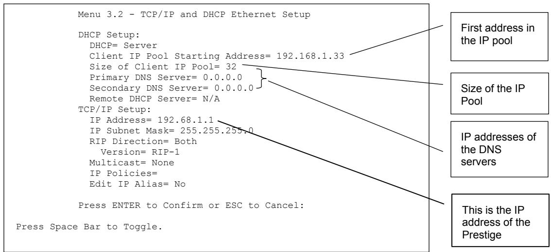
Figure 25-3 Menu 3.2 TCP/IP and DHCP Ethernet Setup
Follow the instructions in the following table on how to configure the DHCP fields.
Table 25-1 DHCP Ethernet Setup Menu Fields
| FIELD | DESCRIPTION | EXAMPLE |
| DHCP Setup | ||
| DHCP | If set to Server, your Prestige can assign IP addresses, an IP default gateway and DNS servers to Windows 95, Windows NT and other systems that support the DHCP client.If set to None, the DHCP server will be disabled.If set to Relay, the Prestige acts as a surrogate DHCP server and relays DHCP requests and responses between the remote server and the clients. Enter the IP address of the actual, remote DHCP server in the Remote DHCP Server in this case.When DHCP is used, the following items need to be set: | Server (default) |
| Client IP Pool Starting Address | This field specifies the first of the contiguous addresses in the IP address pool. | 192.168.1.33 |
| Size of Client IP Pool | This field specifies the size or count of the IP address pool. | 32 |
| Primary DNS Server Secondary DNS Server | Enter the IP addresses of the DNS servers. The DNS servers are passed to the DHCP clients along with the IP address and the subnet mask. | |
| Remote DHCP Server | If Relay is selected in the DHCP field above then enter the IP address of the actual remote DHCP server here. |
Follow the instructions in the following table to configure TCP/IP parameters for the Ethernet port.
Table 25-2 TCP/IP Ethernet Setup Menu Fields
| FIELD | DESCRIPTION | EXAMPLE |
| TCP/IP Setup | ||
| IP Address | Enter the (LAN) IP address of your Prestige in dotted decimal notation | 192.168.1.1 |
| IP Subnet Mask | Your Prestige will automatically calculate the subnet mask based on the IP address that you assign. Unless you are implementing subnetting, use the subnet mask computed by the Prestige. | 255.255.255.0 |
| RIP Direction | Press [SPACE BAR] to select the RIP direction. Choices are Both, In Only, Out Only or None. | Both (default) |
| Version | Press [SPACE BAR] to select the RIP version. Choices are RIP-1, RIP-2B or RIP-2M. | RIP-1 (default) |
Table 25-2 TCP/IP Ethernet Setup Menu Fields
| FIELD | DESCRIPTION | EXAMPLE |
| Multicast | IGMP (Internet Group Multicast Protocol) is a network-layer protocol used to establish membership in a Multicast group. The Prestige supports both IGMP version 1 (IGMP-v1) and version 2 (IGMP-v2).Press the [SPACE BAR] to enable IP Multicasting or select None to disable it. | None (default) |
| IP Policies | Create policies using SMT menu 25 (see the IP Policy Routing chapter) and apply them on the Prestige LAN interface here. You can apply up to four IP Policy sets (from twelve) by entering their numbers separated by commas. | 2,4,7,9 |
| Edit IP Alias | The Prestige supports three logical LAN interfaces via its single physical Ethernet interface with the Prestige itself as the gateway for each LAN network. Press [SPACE BAR] to change No to Yes and press [ENTER] to for menu 3.2.1 | No (default) |
Chapter 26
Wireless LAN Setup
This chapter covers how to configure wireless LAN settings in SMT menu 3.5. This chapter only applies to the Prestige 652H/HW.
26.1 Wireless LAN Overview
Refer to the chapter on the wireless LAN screens for wireless LAN background information.
26.2 Inserting a PCMCIA Wireless LAN Card
Use a ZyAIR series wireless LAN PCMCIA card to add optional wireless LAN capabilities.
Step 1. Turn off the Prestige.
Never insert or remove a wireless LAN card when the Prestige is turned on.
Step 2. Locate the slot labeled Wireless LAN on the Prestige.
Step 3. With its pin connector facing the slot and the LED side facing upwards, slide the ZyAIR wireless LAN card into the slot.
Never force, bend or twist the wireless LAN card into the slot.
Step 4. Turn on the Prestige. The WLAN LED should turn on.
26.3 Wireless LAN Setup
Use menu 3.5 to set up your Prestige as the wireless access point. To edit menu 3.5, enter 3 from the main menu to display Menu 3 – LAN Setup. When menu 3 appears, press 5 and then press [ENTER] to display Menu 3.5 – Wireless LAN Setup as shown next.
Menu 3.5- Wireless LAN Setup
ESSID= Wireless
Hide ESSIS = No
Channel ID= CH01 2412MHz
RTS Threshold= 2432
Frag. Threshold= 2432
WEP= Disable
    Default Key= N/A
    Key1= N/A
    Key2= N/A
    Key3= N/A
    Key4= N/A
Edit MAC Address Filter= No
Press ENTER to Confirm or ESC to Cancel:
Figure 26-1 Menu 3.5 - Wireless LAN Setup
The following table describes the fields in this menu.
Table 26-1 Menu 3.5 - Wireless LAN Setup
| FIELD | DESCRIPTION | EXAMPLE |
| ESSID | The ESSID (Extended Service Set IDentifier) identifies the service set the wireless station is to connect to. Wireless stations associating to the Access Point must have the same ESSID. Enter a descriptive name up to 32 printable 7-bit ASCII characters. | Wireless |
| Hide ESSID | Press [SPACE BAR] and select Yes to hide the ESSID in the outgoing beacon frame so a station cannot obtain the ESSID through passive scanning. | No |
| Channel ID | Press [SPACE BAR] to select a channel. This allows you to set the operating frequency/channel depending on your particular region. | CH012412MHz |
| RTSThreshold | RTS(Request To Send) threshold (number of bytes) enables RTS/CTS handshake. Data with its frame size larger than this value will perform the RTS/CTS handshake. Setting this attribute to be larger than the maximum MSDU (MAC Service Data Unit) size turns off the RTS/CTS handshake. Setting this attribute to zero turns on the RTS/CTS handshake. Enter a value between 0 and 2432. | 2432 |
| Frag.Threshold | The threshold (number of bytes) for the fragmentation boundary for directed messages. It is the maximum data fragment size that can be sent. Enter a value between 256 and 2432. | 2432 |
Table 26-1 Menu 3.5 - Wireless LAN Setup
| FIELD | DESCRIPTION | EXAMPLE |
| WEP | WEP (Wired Equivalent Privacy) provides data encryption to prevent wireless stations from accessing data transmitted over the wireless network.Select Disable allows wireless stations to communicate with the access points without any data encryption.Select 64-bit WEP or 128-bit WEP to for the type of data encryption. WEP causes performance degradation. | Disable |
| Default Key | Enter the number of the key as an active key. | |
| Key 1 to Key 4 | If you chose 64-bit WEP in the WEP Encryption field, then enter 5 characters or 10 hexadecimal characters ("0-9", "A-F") preceded by 0x for each key (1-4). If you chose 128-bit WEP in the WEP Encryption field, then enter 13 characters or 26 hexadecimal characters ("0-9", "A-F") preceded by 0x for each key (1-4).There are four data encryption keys to secure your data from eavesdropping by unauthorized wireless users. The values for the keys must be set up exactly the same on the access points as they are on the wireless stations. | |
| Edit MAC Address Filter | To edit MAC address filtering table, press [SPACE BAR] to select Yes and press [ENTER] to open menu 3.5.1. | No |
| When you have completed this menu, press [ENTER] at the prompt “Press ENTER to confirm or ESC to cancel” to save your configuration or press [ESC] to cancel and go back to the previous screen. | ||
26.3.1 Wireless LAN MAC Address Filter
The next layer of security is MAC address filter. To allow a wireless station to associate with the Prestige, enter the MAC address of the wireless LAN card on that wireless station in the MAC address table.
| Menu 3.5.1 - WLAN MAC Address Filter | |||||
| Active= No Filter Action= Allowed Association | |||||
| 1= | 00:00:00:00:00:00 | 13= | 00:00:00:00:00:00 | 25= | 00:00:00:00:00:00 |
| 2= | 00:00:00:00:00:00 | 14= | 00:00:00:00:00:00 | 26= | 00:00:00:00:00:00 |
| 3= | 00:00:00:00:00:00 | 15= | 00:00:00:00:00:00 | 27= | 00:00:00:00:00:00 |
| 4= | 00:00:00:00:00:00 | 16= | 00:00:00:00:00:00 | 28= | 00:00:00:00:00:00 |
| 5= | 00:00:00:00:00:00 | 17= | 00:00:00:00:00:00 | 29= | 00:00:00:00:00:00 |
| 6= | 00:00:00:00:00:00 | 18= | 00:00:00:00:00:00 | 30= | 00:00:00:00:00:00 |
| 7= | 19 = | 19 = | 19 = 19 = | 31= | 19 = 19 = |
| 8= | 21 = | 21 = | 21 = | 32= | 21 = |
| 9= | 22 = | 22 = | 22 = | ||
| 11= | 23 = | 23 = | 23 = | ||
| 12= | 24 = | 24 = | 24 = | ||
Figure 26-2 Menu 3.5.1 WLAN MAC Address Filtering
The following table describes the fields in this menu.
Table 26-2 Menu 3.5.1 WLAN MAC Address Filtering
| FIELD | DESCRIPTION |
| Active | To enable MAC address filtering, press [SPACE BAR] to select Yes and press [ENTER]. |
| Filter Action | Define the filter action for the list of MAC addresses in the MAC address filter table.To deny access to the Prestige, press [SPACE BAR] to select Deny Association and press [ENTER]. MAC addresses not listed will be allowed to access the router.The default action, Allowed Association, permits association with the Prestige. MAC addresses not listed will be denied access to the router. |
| MAC Address Filter | |
| Address 1.... | Enter the MAC addresses (in XX:XX:XX:XX:XX:XX format) of the wireless stations that are allowed or denied access to the Prestige in these address fields. |
| When you have completed this menu, press [ENTER] at the prompt “Press ENTER to confirm or ESC to cancel” to save your configuration or press [ESC] to cancel and go back to the previous screen. | |
Chapter 27
Internet Access
This chapter shows you how to configure the LAN and WAN of your Prestige for Internet access.
27.1 Internet Access Overview
Refer to the chapters on the web configurator's wizard, LAN and WAN screens for more background information on fields in the SMT screens covered in this chapter.
27.2 IP Policies
Traditionally, routing is based on the destination address only and the router takes the shortest path to forward a packet. IP Policy Routing (IPPR) provides a mechanism to override the default routing behavior and alter the packet forwarding based on the policy defined by the network administrator. Policy-based routing is applied to incoming packets on a per interface basis, prior to the normal routing. Create policies using SMT menu 25 (see IP Policy Routing) and apply them on the Prestige LAN and/or WAN interfaces using menus 3.2 (LAN) and 11.3 (WAN).
27.3 IP Alias
IP Alias allows you to partition a physical network into different logical networks over the same Ethernet interface. The Prestige supports three logical LAN interfaces via its single physical Ethernet interface with the Prestige itself as the gateway for each LAN network.
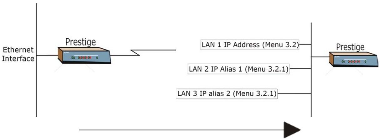
flowchart
graph LR
    A["Ethernet Interface"] --> B["Prestige"]
    B --> C["LAN 1 IP Address (Menu 3.2)"]
    B --> D["LAN 2 IP Alias 1 (Menu 3.2.1)"]
    B --> E["LAN 3 IP alias 2 (Menu 3.2.1)"]
    F["Prestige"] --> G["Output"]
Figure 27-1 Physical Network
Figure 27-2 Partitioned Logical Networks
Use menu 3.2.1 to configure IP Alias on your Prestige.
27.4 IP Alias Setup
Use menu 3.2 to configure the first network. Move the cursor to Edit IP Alias field and press [SPACEBAR] to choose Yes and press [ENTER] to configure the second and third network.
Menu 3.2 - TCP/IP and DHCP Setup
DHCP Setup:
DHCP= Server
Client IP Pool Starting Addres= 192.168.1.33
Size of Client IP Pool= 32
Primary DNS Server= 0.0.0.0
Secondary DNS Server= 0.0.0.0
Remote DHCP Server= N/A
TCP/IP Setup:
IP Address= 192.168.1.1
IP Subnet Mask= 255.255.255.0
RIP Direction= None
Version= N/A
Multicast= None
IP Policies=
Edit IP Alias= Yes

Press ENTER to confirm or ESC to Cancel:
Press Space Bar to Toggle.
Figure 27-3 Menu 3.2 TCP/IP and DHCP Setup
Pressing [ENTER] displays Menu 3.2.1 — IP Alias Setup, as shown next.
Menu 3.2.1 - IP Alias Setup
IP Alias 1= No
    IP Address= N/A
    IP Subnet Mask= N/A
    RIP Direction= N/A
    Version= N/A
    Incoming protocol filters= N/A
    Outgoing protocol filters= N/A
IP Alias 2= No
    IP Address= N/A
    IP Subnet Mask= N/A
    RIP Direction= N/A
    Version= N/A
    Incoming protocol filters= N/A
    Outgoing protocol filters= N/A

Enter here to CONFIRM or ESC to CANCEL:
Figure 27-4 Menu 3.2.1 IP Alias Setup
Follow the instructions in the following table to configure IP Alias parameters.
Table 27-1 Menu 3.2.1 IP Alias Setup
| FIELD | DESCRIPTION | EXAMPLE |
| IP Alias | Choose Yes to configure the LAN network for the Prestige. | Yes |
| IP Address | Enter the IP address of your Prestige in dotted decimal notation | 192.168.2.1 |
| IP Subnet Mask | Your Prestige will automatically calculate the subnet mask based on the IP address that you assign. Unless you are implementing subnetting, use the subnet mask computed by the Prestige | 255.255.255.0 |
| RIP Direction | Press [SPACE BAR] to select the RIP direction. Choices are None, Both, In Only or Out Only. | None |
| Version | Press [SPACE BAR] to select the RIP version. Choices are RIP-1, RIP-2B or RIP-2M. | RIP-1 |
| Incoming Protocol Filters | Enter the filter set(s) you wish to apply to the incoming traffic between this node and the Prestige. | |
| Outgoing Protocol Filters | Enter the filter set(s) you wish to apply to the outgoing traffic between this node and the Prestige. | |
| When you have completed this menu, press [ENTER] at the prompt “Press ENTER to Confirm...” to save your configuration, or press [ESC] at any time to cancel. | ||
27.5 Route IP Setup
The first step is to enable the IP routing in Menu 1 — General Setup.
To edit menu 1, type in 1 in the main menu and press [ENTER]. Set the Route IP field to Yes by pressing [SPACE BAR].
Menu 1 - General Setup
System Name= P652HW
Location= location
Contact Person's Name=
Domain Name=
Edit Dynamic DNS= No
Route IP= Yes
Bridge= No
Press ENTER to Confirm or ESC to Cancel:
Figure 27-5 Menu 1 General Setup
27.6 Internet Access Configuration
Menu 4 allows you to enter the Internet Access information in one screen. Menu 4 is actually a simplified setup for one of the remote nodes that you can access in menu 11. Before you configure your Prestige for Internet access, you need to collect your Internet account information.
Use the Internet Account Information table in the Compact Guide/Read Me First/Quick Start Guide to record your. Note that if you are using PPPoA or PPPoE encapsulation, then the only ISP information you need is a login name and password. You only need to know the Ethernet Encapsulation Gateway IP address if you are using ENET ENCAP encapsulation.
From the main menu, type 4 to display Menu 4 - Internet Access Setup, as shown next.
Menu 4 - Internet Access Setup
ISP's Name= ChangeMe
Encapsulation= ENET ENCAP
Multiplexing= LLC-based
VPI #= 8
VCI #= 35
ATM QoS Type= UBR
    Peak Cell Rate (PCR)= 0
    Sustain Cell Rate (SCR)= 0
    Maximum Burst Size (MBS)= 0
My Login= N/A
My Password= N/A
ENET ENCAP Gateway= N/A
IP Address Assignment= Dynamic
    IP Address= N/A
Network Address Translation= SUA Only
    Address Mapping Set= N/A

Press ENTER to Confirm or ESC to Cancel:
Figure 27-6 Menu 4 Internet Access Setup
The following table contains instructions on how to configure your Prestige for Internet access.
Table 27-2 Menu 4 Internet Access Setup
| FIELD | DESCRIPTION | EXAMPLE |
| ISP's Name | Enter the name of your Internet Service Provider. This information is for identification purposes only. | ChangeMe |
| Encapsulation | Press [SPACE BAR] to select the method of encapsulation used by your ISP. Choices are PPPoE, PPPoA, RFC 1483 or ENET ENCAP. | ENET ENCAP |
Table 27-2 Menu 4 Internet Access Setup
| FIELD | DESCRIPTION | EXAMPLE |
| Multiplexing | Press [SPACE BAR] to select the method of multiplexing used by your ISP. Choices are VC-based or LLC-based. | LLC-based |
| VPI # | Enter the Virtual Path Identifier (VPI) assigned to you. | 8 |
| VCI # | Enter the Virtual Channel Identifier (VCI) assigned to you. | 35 |
| ATM QoS Type | Press [SPACE BAR] and select CBR (Continuous Bit Rate) to specify fixed (always-on) bandwidth. Select UBR (Unspecified Bit Rate) for applications that are non-time sensitive, such as e-mail. Select VBR (Variable Bit Rate) for bursty traffic and bandwidth sharing with other applications. | UBR |
| Peak Cell Rate (PCR) | This is the maximum rate at which the sender can send cells. Type the PCR. | 0 |
| Sustain Cell Rate (SCR)= 0 | Sustained Cell Rate is the mean cell rate of a bursty, on-off traffic source that can be sent at the peak rate, and a parameter for burst-type traffic. Type the SCR; it must be less than the PCR. | 0 |
| Maximum Burst Size (MBS)= 0 | Refers to the maximum number of cells that can be sent at the peak rate. Type the MBS. The MBS must be less than 65535. | 0 |
| My Login | Configure the My Login and My Password fields for PPPoA and PPPoE encapsulation only. Enter the login name that your ISP gives you. If you are using PPPoE encapsulation, then this field must be of the form user@domain where domain identifies your PPPoE service name. | N/A |
| My Password | Enter the password associated with the login name above. | N/A |
| ENET ENCAP Gateway | Enter the gateway IP address supplied by your ISP when you are using ENET ENCAP encapsulation. | N/A |
| Idle Timeout | This value specifies the number of idle seconds that elapse before the Prestige automatically disconnects the PPPoE session. | 0 |
| IP Address Assignment | Press [SPACE BAR] to select Static or Dynamic address assignment. | Dynamic |
| IP Address | Enter the IP address supplied by your ISP if applicable. | N/A |
Table 27-2 Menu 4 Internet Access Setup
| FIELD | DESCRIPTION | EXAMPLE |
| Network Address Translation | Press [SPACE BAR] to select None, SUA Only or Full Feature. Please see the NAT Chapter for more details on the SUA (Single User Account) feature. | SUA Only |
| Address Mapping Set | Type the numbers of mapping sets (1-8) to use with NAT. See the NAT chapter for details. | N/A |
| When you have completed this menu, press [ENTER] at the prompt “Press ENTER to confirm or ESC to cancel” to save your configuration or press [ESC] to cancel and go back to the previous screen. | ||
If all your settings are correct your Prestige should connect automatically to the Internet. If the connection fails, note the error message that you receive on the screen and take the appropriate troubleshooting steps.
Chapter 28
Remote Node Configuration
This chapter covers remote node configuration.
28.1 Remote Node Setup Overview
This section describes the protocol-independent parameters for a remote node. A remote node is required for placing calls to a remote gateway. A remote node represents both the remote gateway and the network behind it across a WAN connection. When you use menu 4 to set up Internet access, you are configuring one of the remote nodes.
You first choose a remote node in Menu 11- Remote Node Setup. You can then edit that node's profile in menu 11.1, as well as configure specific settings in three submenus: edit IP and bridge options in menu 11.3; edit ATM options in menu 11.6; and edit filter sets in menu 11.5.
28.2 Remote Node Setup
This section describes the protocol-independent parameters for a remote node.
28.2.1 Remote Node Profile
To configure a remote node, follow these steps:
Step 1. From the main menu, enter 11 to display Menu 11 - Remote Node Setup.
Step 2. When menu 11 appears, as shown in the following figure, type the number of the remote node that you want to configure.
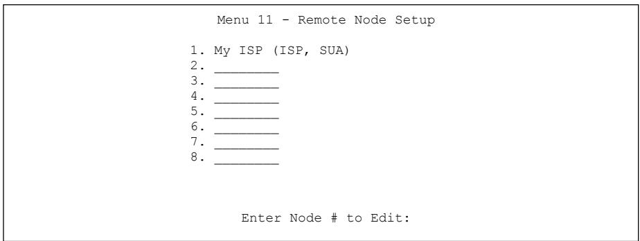
Figure 28-1 Menu 11 Remote Node Setup
28.2.2 Encapsulation and Multiplexing Scenarios
For Internet access you should use the encapsulation and multiplexing methods used by your ISP. Consult your telephone company for information on encapsulation and multiplexing methods for LAN-to-LAN applications, for example between a branch office and corporate headquarters. There must be prior agreement on encapsulation and multiplexing methods because they cannot be automatically determined. What method(s) you use also depends on how many VCs you have and how many different network protocols you need. The extra overhead that ENET ENCAP encapsulation entails makes it a poor choice in a LAN-to-LAN application. Here are some examples of more suitable combinations in such an application.
Scenario 1. One VC, Multiple Protocols
PPPoA (RFC-2364) encapsulation with VC-based multiplexing is the best combination because no extra protocol identifying headers are needed. The PPP protocol already contains this information.
Scenario 2. One VC, One Protocol (IP)
Selecting RFC-1483 encapsulation with VC-based multiplexing requires the least amount of overhead (0 octets). However, if there is a potential need for multiple protocol support in the future, it may be safer to select PPPoA encapsulation instead of RFC-1483, so you do not need to reconfigure either computer later.
Scenario 3. Multiple VCs
If you have an equal number (or more) of VCs than the number of protocols, then select RFC-1483 encapsulation and VC-based multiplexing.
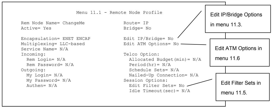
flowchart
graph TD
    A["Menu 11.1 - Remote Node Profile"] --> B["Edit IP/Bridge Options in menu 11.3."]
    B --> C["Edit ATM Options in menu 11.6"]
    C --> D["Edit Filter Sets in menu 11.5."]
    A --> E["Rem Node Name= ChangeMe\nActive= Yes"]
    A --> F["Route= IP\nBridge= No"]
    A --> G["Encapsulation= ENET ENCAP\nMultiplexing= LLC-based\nService Name= N/A"]
    A --> H["Incoming:\nRem Login= N/A\nRem Password= N/A\nOutgoing:\nMy Login= N/A\nMy Password= N/A\nAuthen= N/A"]
    A --> I["Edit IP/Bridge= No\nEdit ATM Options= No"]
    A --> J["Telco Option:\nAllocated Budget(min)= N/A\nPeriod(hr)= N/A\nSchedule Sets= N/A\nNailed-Up Connection= N/A\nSession Options:\nEdit Filter Sets= No\nIdle Timeout(sec)= N/A"]
Figure 28-2 Menu 11.1 Remote Node Profile
In Menu 11.1 – Remote Node Profile, fill in the fields as described in the following table.
Table 28-1 Menu 11.1 Remote Node Profile
| FIELD | DESCRIPTION | EXAMPLE |
| Rem Node Name | Type a unique, descriptive name of up to eight characters for this node. | myISP |
| Active | Press [SPACE BAR] and then [ENTER] to select Yes to activate or No to deactivate this node. Inactive nodes are displayed with a minus sign “-” in SMT menu 11. | Yes |
| Encapsulation | PPPoA refers to RFC-2364 (PPP Encapsulation over ATM Adaptation Layer 5).If RFC-1483 (Multiprotocol Encapsulation over ATM Adaptation Layer 5) of ENET ENCAP are selected,then the Rem Login, Rem Password, My Login, My Password and Authen fields are not applicable (N/A). | ENETENCAP |
| Multiplexing | Press [SPACE BAR] and then [ENTER] to select the method of multiplexing that your ISP uses, either VC-based or LLC-based. | LLC-based |
| Service Name | When using PPPoE encapsulation, type the name of your PPPoE service here. | N/A |
| Incoming: |
Table 28-1 Menu 11.1 Remote Node Profile
| FIELD | DESCRIPTION | EXAMPLE |
| Rem Login | Type the login name that this remote node will use to call your Prestige. The login name and the Rem Password will be used to authenticate this node. | |
| Rem Password | Type the password used when this remote node calls your Prestige. | |
| Outgoing: | ||
| My Login | Type the login name assigned by your ISP when the Prestige calls this remote node. | |
| My Password | Type the password assigned by your ISP when the Prestige calls this remote node. | |
| Authen | This field sets the authentication protocol used for outgoing calls. Options for this field are:CHAP/PAP – Your Prestige will accept either CHAP or PAP when requested by this remote node.CHAP – accept CHAP (Challenge Handshake Authentication Protocol) only.PAP – accept PAP (Password Authentication Protocol) only. | |
| Route | This field determines the protocol used in routing. Options are IP and None. | IP |
| Bridge | When bridging is enabled, your Prestige will forward any packet that it does not route to this remote node; otherwise, the packets are discarded. Select Yes to enable and No to disable. | No |
| Edit IP/Bridge | Press [SPACE BAR] to select Yes and press [ENTER] to display Menu 11.3 – Remote Node Network Layer Options. | No |
| Edit ATM Options | Press [SPACE BAR] to select Yes and press [ENTER] to display Menu 11.6 – Remote Node ATM Layer Options. | No |
| Edit Advance Options | This field is only available when you select PPPoE in the Encapsulation field.Press [SPACE BAR] to select Yes and press [ENTER] to display Menu 11.8 – Advance Setup Options. This field is not available on all models. | No |
| Telco Option | ||
| Allocated Budget | This sets a ceiling for outgoing call time for this remote node. The |
Table 28-1 Menu 11.1 Remote Node Profile
| FIELD | DESCRIPTION | EXAMPLE |
| (min) | default for this field is 0 meaning no budget control. | |
| Period (hr) | This field is the time period that the budget should be reset. For example, if we are allowed to call this remote node for a maximum of 10 minutes every hour, then theAllocated Budgetis (10 minutes) and thePeriod (hr)is 1 (hour). | |
| Schedule Sets | This field is only applicable for PPPoEand PPPoAencapsulation. You can apply up to four schedule sets here. For more details please refer to theCall Schedule Setupchapter. | |
| Nailed up Connection | This field is only applicable for PPPoEand PPPoAencapsulation. This field specifies if you want to make the connection to this remote node a nailed-up connection. More details are given earlier in this section. | |
| Session Options | ||
| Edit Filter Sets | Use [SPACE BAR] to chooseYesand press [ENTER] to open menu 11.5 to edit the filter sets. See theRemote Node Filtersection for more details. | No (default) |
| Idle Timeout (sec) | Type the number of seconds (0-9999) that can elapse when the Prestige is idle (there is no traffic going to the remote node), before the Prestige automatically disconnects the remote node. 0 means that the session will not timeout. | |
| When you have completed this menu, press [ENTER] at the prompt “Press ENTER to confirm or ESC to cancel” to save your configuration or press [ESC] to cancel and go back to the previous screen. | ||
28.2.3 Outgoing Authentication Protocol
For obvious reasons, you should employ the strongest authentication protocol possible. However, some vendors' implementation includes specific authentication protocol in the user profile. It will disconnect if the negotiated protocol is different from that in the user profile, even when the negotiated protocol is stronger than specified. If the peer disconnects right after a successful authentication, make sure that you specify the correct authentication protocol when connecting to such an implementation.
28.3 Remote Node Network Layer Options
For the TCP/IP parameters, perform the following steps to edit Menu 11.3 – Remote Node Network Layer Options as shown next.
Step 1. In menu 11.1, make sure IP is among the protocols in the Route field.
Step 2. Move the cursor to the Edit IP/Bridge field, press [SPACE BAR] to select Yes, then press [ENTER] to display Menu 11.3 – Remote Node Network Layer Options.
Menu 11.3 - Remote Node Network Layer Options
IP Options: Bridge Options:
IP Address Assignment= Dynamic Ethernet Addr Timeout (min)= N/A
Rem IP Addr: 0.0.0.0
Rem Subnet Mask= 0.0.0.0
My WAN Addr= 0.0.0.0
NAT= Full Feature
Address Mapping Set= 2
Metric= 2
Private= No
RIP Direction= None
Version= RIP-1
Multicast= None
IP Policies= 3,4,5,6
Press ENTER to Confirm or ESC to Cancel:
Figure 28-3 Menu 11.3 Remote Node Network Layer Options
The next table explains fields in Menu 11.3 - Remote Node Network Layer Options.
Table 28-2 Menu 11.3 Remote Node Network Layer Options
| FIELD | DESCRIPTION | EXAMPLE |
| IP Address Assignment | Press [SPACE BAR] and then [ENTER] to selectDynamicif the remote node is using a dynamically assigned IP address orStaticif it is using a static (fixed) IP address. You will only be able to configure this in the ISP node (also the one you configure in menu 4),all other nodes are set to Static. | Dynamic |
| Rem IP Addr | This is the IP address you entered in the previous menu. | |
| Rem Subnet Mask | Type the subnet mask assigned to the remote node. |
Table 28-2 Menu 11.3 Remote Node Network Layer Options
| FIELD | DESCRIPTION | EXAMPLE |
| My WAN Addr | Some implementations, especially UNIX derivatives, require separate IP network numbers for the WAN and LAN links and each end to have a unique address within the WAN network number. In that case, type the IP address assigned to the WAN port of your Prestige.NOTE: Refers to local Prestige address, not the remote router address. | |
| NAT | Press [SPACE BAR] and then [ENTER] to select Full Feature if you have multiple public WAN IP addresses for your Prestige.Select SUA Only if you have just one public WAN IP address for your Prestige. The SMT uses Address Mapping Set 255 (menu 15.1 - see section 31.3.1).Select None to disable NAT. | SUA Only |
| Address Mapping Set | When Full Feature is selected in the NAT field, configure address mapping sets in menu 15.1. Select one of the NAT server sets (2-10) in menu 15.2 (see the NAT chapter for details) and type that number here.When SUA Only is selected in the NAT field, the SMT uses NAT server set 1 in menu 15.2 (see the NAT chapter for details). | 2 |
| Metric | The metric represents the “cost” of transmission for routing purposes. IP routing uses hop count as the cost measurement, with a minimum of 1 for directly connected networks. Type a number that approximates the cost for this link. The number need not be precise, but it must be between 1 and 15. In practice, 2 or 3 is usually a good number. | 2 |
| Private | This determines if the Prestige will include the route to this remote node in its RIP broadcasts. If set to Yes, this route is kept private and not included in RIP broadcast. If No, the route to this remote node will be propagated to other hosts through RIP broadcasts. | No |
| RIP Direction | Press [SPACE BAR] and then [ENTER] to select the RIP Direction. Options are Both, In Only, Out Only or None. | None |
| Version | Press [SPACE BAR] and then [ENTER] to select the RIP version. Options are RIP-1, RIP-2B or RIP-2M. | RIP-1 |
| Multicast | IGMP-v1 sets IGMP to version 1, IGMP-v2 sets IGMP to version 2 and None disables IGMP. | None |
| IP Policies | You can apply up to four IP Policy sets (from 12) by typing in their numbers separated by commas. Configure the filter sets in menu 25 first (see the IP Policy Routing chapter) and then apply them here. | 3, 4, 5, 6 |
Table 28-2 Menu 11.3 Remote Node Network Layer Options
| FIELD | DESCRIPTION | EXAMPLE |
| When you have completed this menu, press [ENTER] at the prompt “Press ENTER to confirm or ESC to cancel” to save your configuration or press [ESC] to cancel and go back to the previous screen. | ||
28.3.1 My WAN Addr Sample IP Addresses
The following figure uses sample IP addresses to help you understand the field of My Wan Addr in menu 11.3. Refer to the previous Figure 5-1 LAN and WAN IP Addresses for a brief review of what a WAN IP is. My WAN Addr indicates the local Prestige WAN IP while Rem IP Addr indicates the peer WAN IP.
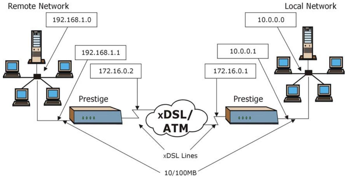
flowchart
graph TD
    A["Remote Network"] -->|192.168.1.0| B["Prestige"]
    A -->|192.168.1.1| B
    A -->|172.16.0.2| B
    C["Local Network"] -->|10.0.0.0| D["Prestige"]
    C -->|10.0.0.1| D
    C -->|172.16.0.1| D
    D --> E["xDSL/ATM"]
    E --> F["xDSL Lines"]
    F --> G["10/100MB"]
    G --> H["Computer"]
    style A fill:#f9f,stroke:#333
    style C fill:#f9f,stroke:#333
    style B fill:#bbf,stroke:#333
    style D fill:#bbf,stroke:#333
    style E fill:#dfd,stroke:#333
    style F fill:#dfd,stroke:#333
    style G fill:#dfd,stroke:#333
Figure 28-4 Sample IP Addresses for a TCP/IP LAN-to-LAN Connection
28.4 Remote Node Filter
Move the cursor to the Edit Filter Sets field in menu 11.1, then press [SPACE BAR] to select Yes. Press [ENTER] to display Menu 11.5 – Remote Node Filter.
Use Menu 11.5 – Remote Node Filter to specify the filter set(s) to apply to the incoming and outgoing traffic between this remote node and the Prestige and also to prevent certain packets from triggering calls. You can specify up to 4 filter sets separated by comma, for example, 1, 5, 9, 12, in each filter field.
Note that spaces are accepted in this field. The Prestige has a prepackaged filter set, NetBIOS_WAN, that blocks NetBIOS packets. Include this in the call filter sets if you want to prevent NetBIOS packets from triggering calls to a remote node.
Menu 11.5 - Remote Node Filter
Input Filter Sets:
protocol filters= 11, 12
device filters=
Output Filter Sets:
protocol filters=
device filters=
Enter here to CONFIRM or ESC to CANCEL:
Figure 28-5 Menu 11.5 Remote Node Filter (RFC 1483 or ENET Encapsulation)
Menu 11.5 - Remote Node Filter
Input Filter Sets:
protocol filters= 11, 12
device filters=
Output Filter Sets:
protocol filters=
device filters=
Call Filter Sets:
Protocol filters=
Device filters=
Enter here to CONFIRM or ESC to CANCEL:
Figure 28-6 Menu 11.5 Remote Node Filter (PPPoA or PPPoE Encapsulation)
28.5 Editing ATM Layer Options
Follow the steps shown next to edit Menu 11.6 – Remote Node ATM Layer Options.
In menu 11.1, move the cursor to the Edit ATM Options field and then press [SPACE BAR] to select Yes. Press [ENTER] to display Menu 11.6 – Remote Node ATM Layer Options.
There are two versions of menu 11.6 for the Prestige, depending on whether you chose VC-based/LLC-based multiplexing and PPP encapsulation in menu 11.1.
28.5.1 VC-based Multiplexing (non-PPP Encapsulation)
For VC-based multiplexing, by prior agreement, a protocol is assigned a specific virtual circuit, for example, VC1 will carry IP. Separate VPI and VCI numbers must be specified for each protocol.
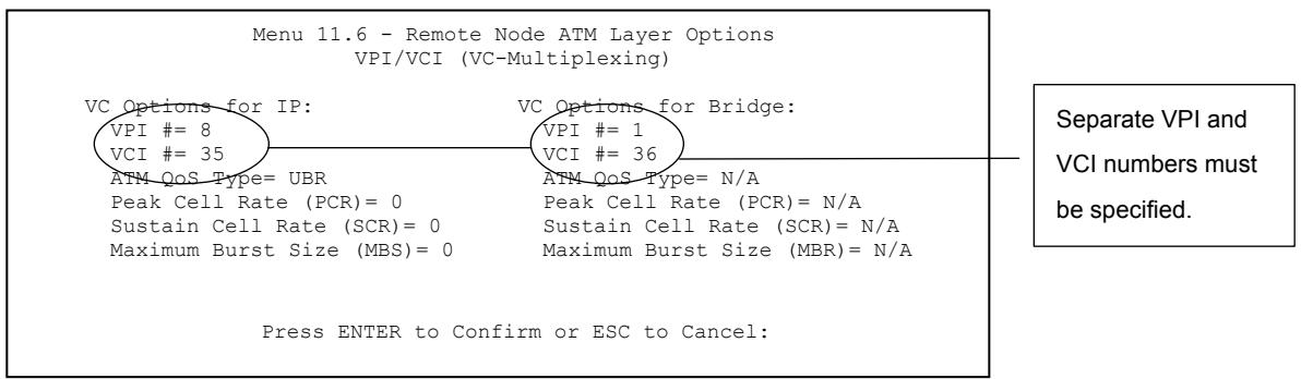
Figure 28-7 Menu 11.6 for VC-based Multiplexing
28.5.2 LLC-based Multiplexing or PPP Encapsulation
For LLC-based multiplexing or PPP encapsulation, one VC carries multiple protocols with protocol identifying information being contained in each packet header.
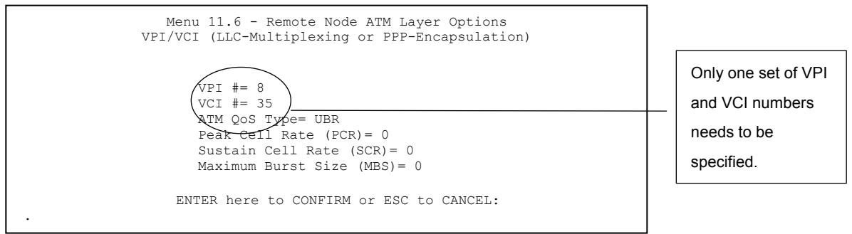
Figure 28-8 Menu 11.6 for LLC-based Multiplexing or PPP Encapsulation
In this case, only one set of VPI and VCI numbers need be specified for all protocols. The valid range for the VPI is 0 to 255 and for the VCI is 32 to 65535 (1 to 31 is reserved for local management of ATM traffic).
28.5.3 Advance Setup Options
In menu 11.1, select PPPoE in the Encapsulation field.
Menu 11.1 - Remote Node Profile
Rem Node Name= MyISP Route= IP
Active= Yes Bridge= No
Encapsulation= PPPoE Edit IP/Bridge= No
Multiplexing= LLC-based Edit ATM Options= No
Service Name= Edit Advance Options= Yes
Incoming: Telco Option:
Rem Login= Allocated Budget(min)= 0
Rem Password= ******* Period(hr)= 0
Outgoing: Schedule Sets=
My Login= ? Nailed-Up Connection= No
My Password= ? Session Options:
Authen= CHAP/PAP Edit Filter Sets= No
Idle Timeout(sec)= 0
Press ENTER to Confirm or ESC to Cancel:
Figure 28-9 Menu 11.1 Remote Node Profile
Move the cursor to the Edit Advance Options field, press [SPACE BAR] to select Yes, then press [ENTER] to display Menu 11.8 – Advance Setup Options.
Menu 11.8 - Advance Setup Options
PPPoE + PPPoE_Client_PC= No
Press ENTER to Confirm or ESC to Cancel:
Figure 28-10 Menu 11.8 Advance Setup Options
The following table describes the fields in this menu.
Table 28-3 Menu 11.8 Advance Setup Options
| FIELD | DESCRIPTION |
| PPPoE+PPPoE_Client_PC | Press [SPACE BAR] to selectYesand press [ENTER] to enable PPPoE pass through. In addition to the Prestige's built-in PPPoE client, you can enable PPPoE pass through to allow up to ten hosts on the LAN to use PPPoE client software on their computers to connect to the ISP via the Prestige. Each host can have a separate account and a public WAN IP address.PPPoE pass through is an alternative to NAT for applications where NAT is not appropriate.Press [SPACE BAR] to selectNoand press [ENTER] to disable PPPoE pass through if you do not need to allow hosts on the LAN to use PPPoE client software on their computers to connect to the ISP. |
| When you have completed this menu, press [ENTER] at the prompt “Press ENTER to confirm or ESC to cancel” to save your configuration or press [ESC] to cancel and go back to the previous screen. | |
Chapter 29
Static Route Setup
This chapter shows how to setup IP static routes.
29.1 IP Static Route Overview
Static routes tell the Prestige routing information that it cannot learn automatically through other means. This can arise in cases where RIP is disabled on the LAN or a remote network is beyond the one that is directly connected to a remote node.
Each remote node specifies only the network to which the gateway is directly connected and the Prestige has no knowledge of the networks beyond. For instance, the Prestige knows about network N2 in the following figure through remote node Router 1. However, the Prestige is unable to route a packet to network N3 because it does not know that there is a route through remote node Router 1 (via Router 2). The static routes allow you to tell the Prestige about the networks beyond the remote nodes.
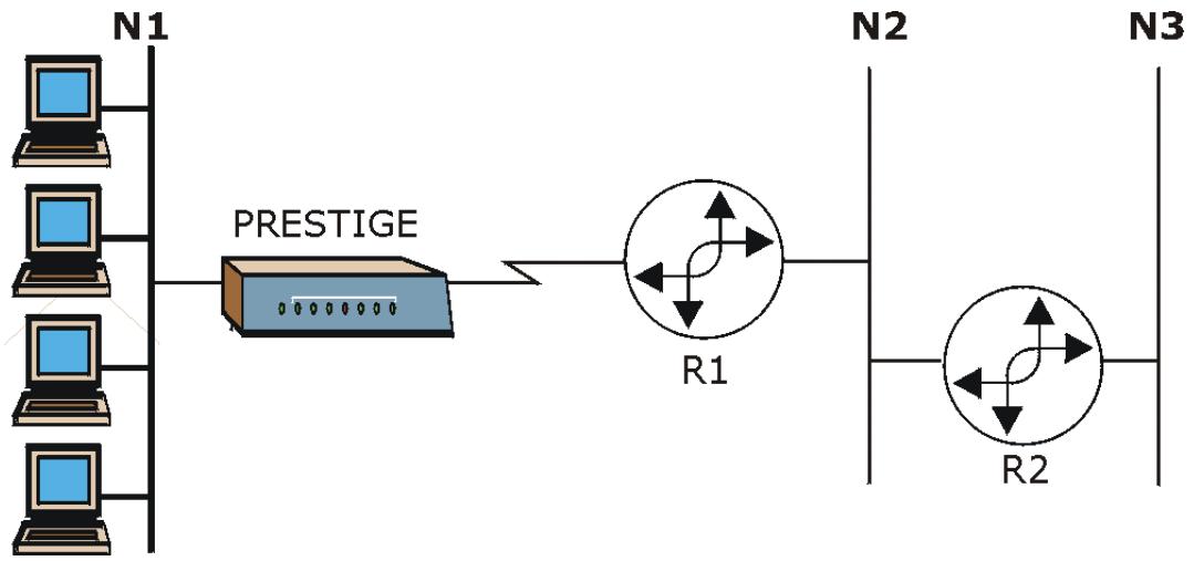
flowchart
graph LR
    N1["Computer 1"] --> PPESTIGE["Prestige"]
    N2["Computer 2"] --> PPESTIGE
    N3["Computer 3"] --> PPESTIGE
    PPESTIGE --> R1["R1"]
    R1 --> R2["R2"]
    R2 --> N3
Figure 29-1 Sample Static Routing Topology
29.2 Configuration
Step 1. To configure an IP static route, use Menu 12 – Static Route Setup (shown next).
Menu 12 - Static Route Setup
1. IP Static Route
3. Bridge Static Route
Please enter selection:
Figure 29-2 Menu 12 Static Route Setup
Step 2. From menu 12, select 1 to open Menu 12.1 — IP Static Route Setup (shown next).
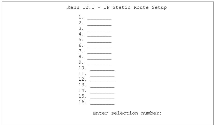
Figure 29-3 Menu 12.1 IP Static Route Setup (P652H/HW)
Step 3. Now, type the route number of a static route you want to configure.
Menu 12.1.1 - Edit IP Static Route
Route #: 1
Route Name = ?
Active = No
Destination IP Address = ?
IP Subnet Mask = ?
Gateway IP Address = ?
Metric = 2
Private = No
Press ENTER to Confirm or ESC to Cancel:
Figure 29-4 Menu12.1.1 Edit IP Static Route
The following table describes the fields for Menu 12.1.1 – Edit IP Static Route Setup.
Table 29-1 Menu12.1.1 Edit IP Static Route
| FIELD | DESCRIPTION |
| Route # | This is the index number of the static route that you chose in menu 12.1. |
| Route Name | Type a descriptive name for this route. This is for identification purpose only. |
| Active | This field allows you to activate/deactivate this static route. |
| Destination IP Address | This parameter specifies the IP network address of the final destination. Routing is always based on network number. If you need to specify a route to a single host, use a subnet mask of 255.255.255.255 in the subnet mask field to force the network number to be identical to the host ID. |
| IP Subnet Mask | Type the subnet mask for this destination. Follow the discussion on IP Subnet Mask in this manual. |
| Gateway IP Address | Type the IP address of the gateway. The gateway is an immediate neighbor of your Prestige that will forward the packet to the destination. On the LAN, the gateway must be a router on the same segment as your Prestige; over WAN, the gateway must be the IP address of one of the remote nodes. |
| Metric | Metric represents the “cost” of transmission for routing purposes. IP routing uses hop count as the measurement of cost, with a minimum of 1 for directly connected networks. Type a number that approximates the cost for this link. The number need not be precise, but it must be between 1 and 15. In practice, 2 or 3 is usually a good number. |
Table 29-1 Menu12.1.1 Edit IP Static Route
| FIELD | DESCRIPTION |
| Private | This parameter determines if the Prestige will include the route to this remote node in its RIP broadcasts. If set to Yes, this route is kept private and is not included in RIP broadcasts. If No, the route to this remote node will be propagated to other hosts through RIP broadcasts. |
| When you have completed this menu, press [ENTER] at the prompt “Press ENTER to confirm or ESC to cancel” to save your configuration or press [ESC] to cancel and go back to the previous screen. | |
Chapter 30
Bridging Setup
This chapter shows you how to configure the bridging parameters of your Prestige.
30.1 Bridging in General
Bridging bases the forwarding decision on the MAC (Media Access Control), or hardware address, while routing does it on the network layer (IP) address. Bridging allows the Prestige to transport packets of network layer protocols that it does not route, for example, SNA, from one network to another. The caveat is that, compared to routing, bridging generates more traffic for the same network layer protocol, and it also demands more CPU cycles and memory.
For efficiency reasons, do not turn on bridging unless you need to support protocols other than IP on your network. For IP, enable the routing if you need it; do not bridge what the Prestige can route.
30.2 Bridge Ethernet Setup
Basically, all non-local packets are bridged to the WAN. Your Prestige does not support IPX.
30.2.1 Remote Node Bridging Setup
Follow the procedure in another section to configure the protocol-independent parameters in Menu 11.1 – Remote Node Profile. For bridging-related parameters, you need to configure Menu 11.3 – Remote Node Network Layer Options.
To setup Menu 11.3 – Remote Node Network Layer Options shown in the next figure, follow these steps:
Step 1. In menu 11.1, make sure the Bridge field is set to Yes.
Menu 11.1 - Remote Node Profile
Rem Node Name= ?
Active= Yes
Route= IP
Bridge= Yes
Encapsulation= ENET ENCAP
Multiplexing= VC-based
Service Name= N/A
Incoming:
    Rem Login= N/A
    Rem Password= N/A
Outgoing:
    My Login= N/A
    My Password= N/A
    Authen= N/A
Edit IP/Bridge= No
Edit ATM Options= No
Telco Option:
Allocated Budget(min)= N/A
Period(hr)= N/A
Schedule Sets= N/A
Nailed-Up Connection= N/A
Session Options:
Edit Filter Sets= No
Idle Timeout(sec)= N/A
Press ENTER to Confirm or ESC to Cancel:
Figure 30-1 Menu 11.1 Remote Node Profile
Step 2. Move the cursor to the Edit IP/Bridge field, then press [SPACE BAR] to set the value to Yes and press [ENTER] to edit Menu 11.3 – Remote Node Network Layer Options.
Menu 11.3 - Remote Node Network Layer Options
IP Options: Bridge Options:
IP Address Assignment= Static Ethernet Addr Timeout (min)= 0
Rem IP Addr: 0.0.0.0
Rem Subnet Mask= 0.0.0.0
My WAN Addr= 0.0.0.0
NAT= Full Feature
Address Mapping Set=2
Metric= 2
Private= No
RIP Direction= Both
Version= RIP-2B
Multicast= IGMP-v2
IP Policies=
Figure 30-2 Menu 11.3 Remote Node Network Layer Options
Table 30-1 Remote Node Network Layer Options : Bridge Fields
| FIELD | DESCRIPTION |
| Bridge (menu 11.1) | Make sure this field is set to Yes. |
| Edit IP/Bridge (menu 11.1) | Press [SPACE BAR] to select Yes and press [ENTER] to display menu 11.3. |
| Ethernet Addr Timeout (min.) (menu 11.3) | Type the time (in minutes) for the Prestige to retain the Ethernet Address information in its internal tables while the line is down. If this information is retained, your Prestige will not have to recompile the tables when the line comes back up. |
| When you have completed this menu, press [ENTER] at the prompt “Press ENTER to confirm or ESC to cancel” to save your configuration or press [ESC] to cancel and go back to the previous screen. | |
30.2.2 Bridge Static Route Setup
Similar to network layer static routes, a bridging static route tells the Prestige the route to a node before a connection is established. You configure bridge static routes in menu 12.3.1 (go to menu 12, choose option 3, then choose a static route to edit) as shown next.
| Menu 12.3.1 - Edit Bridge Static Route |
| Route #: 1 Route Name= Active= No Ether Address= ? IP Address= Gateway Node= 1 |
| Press ENTER to Confirm or ESC to Cancel: |
Figure 30-3 Menu 12.3.1 Edit Bridge Static Route
The following table describes the Edit Bridge Static Route menu.
Table 30-2 Menu 12.3.1 Edit Bridge Static Route
| FIELD | DESCRIPTION |
| Route # | This is the route index number you typed in Menu 12.3 – Bridge Static Route Setup. |
| Route Name | Type a name for the bridge static route for identification purposes. |
| Active | Indicates whether the static route is active (Yes) or not (No). |
| Ether Address | Type the MAC address of the destination computer that you want to bridge the packets to. |
| IP Address | If available, type the IP address of the destination computer that you want to bridge the packets to. |
| Gateway Node | Press [SPACE BAR] and then [ENTER] to select the number of the remote node (one to eight) that is the gateway of this static route. |
| When you have completed this menu, press [ENTER] at the prompt “Press ENTER to confirm or ESC to cancel” to save your configuration or press [ESC] to cancel and go back to the previous screen. | |
Chapter 31
Network Address Translation (NAT)
This chapter discusses how to configure NAT on the Prestige.
31.1 Using NAT
You must create a firewall rule in addition to setting up SUA/NAT, to allow traffic from the WAN to be forwarded through the Prestige.
31.1.1 SUA (Single User Account) Versus NAT
SUA (Single User Account) is a ZyNOS implementation of a subset of NAT that supports two types of mapping, Many-to-One and Server. See section 31.3.1 for a detailed description of the NAT set for SUA. The Prestige also supports Full Feature NAT to map multiple global IP addresses to multiple private LAN IP addresses of clients or servers using mapping types as outlined in the Web Configurator User's Guide.
- Choose SUA Only if you have just one public WAN IP address for your Prestige.
- Choose Full Feature if you have multiple public WAN IP addresses for your Prestige.
31.2 Applying NAT
You apply NAT via menus 4 or 11.3 as displayed next. The next figure shows you how to apply NAT for Internet access in menu 4. Enter 4 from the main menu to go to Menu 4 - Internet Access Setup.
| Menu 4 - Internet Access Setup |
| ISP's Name= MyISP Encapsulation= RFC 1483 Multiplexing= LLC-based VPI #= 8 VCI #= 35 ATM QoS Type= UBR Peak Cell Rate (PCR)= 0 Sustain Cell Rate (SCR)= 0 Maximum Burst Size (MBS)= 0 My Login= N/A My Password= N/A ENET ENCAP Gateway= N/A IP Address Assignment= Static IP Address= 0.0.0.0 Network Address Translation= SUA Only Address Mapping Set= N/A |
| Press ENTER to Confirm or ESC to Cancel: |
Figure 31-1 Menu 4 Applying NAT for Internet Access
The following figure shows how you apply NAT to the remote node in menu 11.1.
Step 1. Enter 11 from the main menu.
Step 2. When menu 11 appears, as shown in the following figure, type the number of the remote node that you want to configure.
Step 3. Move the cursor to the Edit IP/Bridge field, press [SPACE BAR] to select Yes and then press [ENTER] to bring up Menu 11.3 - Remote Node Network Layer Options.
Menu 11.3 - Remote Node Network Layer Options
IP Options: Bridge Options:
IP Address Assignment = Dynamic Ethernet Addr Timeout(min)= N/A
Rem IP Addr = 0.0.0.0
Rem Subnet Mask= 0.0.0.0
My WAN Addr= N/A
NAT= SUA Only
Address Mapping Set= N/A
Metric= 2
Private= No
RIP Direction= None
Version= RIP-1
Multicast= None
IP Policies=

Enter here to CONFIRM or ESC to CANCEL:
Figure 31-2 Menu 11.3 Applying NAT to the Remote Node
The following table describes the options for Network Address Translation.
Table 31-1 Applying NAT in Menus 4 & 11.3
| FIELD | DESCRIPTION | EXAMPLE |
| NAT | Press [SPACE BAR] and then [ENTER] to select Full Feature if you have multiple public WAN IP addresses for your Prestige. The SMT uses the address mapping set that you configure and enter in the Address Mapping Set field (menu 15.1 - see section 31.3.1). | Full Feature |
| Select None to disable NAT. | None | |
| When you select SUA Only, the SMT uses Address Mapping Set 255 (menu 15.1 - see section 31.3.1). Choose SUA Only if you have just one public WAN IP address for your Prestige. | SUA Only |
31.3 NAT Setup
Use the address mapping sets menus and submenus to create the mapping table used to assign global addresses to computers on the LAN and the DMZ. You can see two NAT address mapping sets in menu 15.1. You can only configure Set 1. Set 255 is used for SUA. When you select Full Feature in menu 4 or 11.3, the SMT will use Set 1. When you select SUA Only, the SMT will use the pre-configured Set 255 (read only).
The server set is a list of LAN and DMZ servers mapped to external ports. To use this set, a server rule must be set up inside the NAT address mapping set. Please see the section on port forwarding in the chapter on NAT web configurator screens for further information on these menus. To configure NAT, enter 15 from the main menu to bring up the following screen.
Menu 15 - NAT Setup
1. Address Mapping Sets
2. NAT Server Sets
Enter Menu Selection Number:
Figure 31-3 Menu 15 NAT Setup
31.3.1 Address Mapping Sets
Enter 1 to bring up Menu 15.1 — Address Mapping Sets.
Menu 15.1 - Address Mapping Sets
1.
2.
3.
4.
5.
6.
7.
8.
255. SUA (read only)
Enter Menu Selection Number:
Enter Menu Selection Number:
Figure 31-4 Menu 15.1 Address Mapping Sets
SUA Address Mapping Set
Enter 255 to display the next screen (see also section 31.1.1). The fields in this menu cannot be changed.
| Menu 15.1.255 - Address Mapping Rules | |||||
| Set Name= | |||||
| Idx | Local Start IP | Local End IP | Global Start IP | Global End IP | Type |
| 1. | 0.0.0.0 | 255.255.255.255 | 0.0.0.0 | M-1 | |
| 2. | 0.0.0.0 | Server | |||
| 3. | |||||
| 4. | |||||
| 5. | |||||
| 6. | |||||
| 7. | |||||
| 8. | |||||
| 9. | |||||
| 10. | |||||
| Press ENTER to Confirm or ESC to Cancel: | |||||
Figure 31-5 Menu 15.1.255 SUA Address Mapping Rules
The following table explains the fields in this menu.
Menu 15.1.255 is read-only.
Table 31-2 SUA Address Mapping Rules
| FIELD | DESCRIPTION | EXAMPLE |
| Set Name | This is the name of the set you selected in menu 15.1 or enter the name of a new set you want to create. | SUA |
| Idx | This is the index or rule number. | 1 |
| Local Start IP | Local Start IP is the starting local IP address (ILA). | 0.0.0.0 |
| Local End IP | Local End IP is the ending local IP address (ILA). If the rule is for all local IPs, then the Start IP is 0.0.0.0 and the End IP is 255.255.255.255. | 255.255.255.255 |
| Global Start IP | This is the starting global IP address (IGA). If you have a dynamic IP, enter 0.0.0.0 as the Global Start IP. | 0.0.0.0 |
| Global End IP | This is the ending global IP address (IGA). | |
| Type | These are the mapping types. Server allows us to specify multiple servers of different types behind NAT to this machine. See later for some examples. | Server |
Table 31-2 SUA Address Mapping Rules
| FIELD | DESCRIPTION | EXAMPLE |
| When you have completed this menu, press [ENTER] at the prompt “Press ENTER to confirm or ESC to cancel” to save your configuration or press [ESC] to cancel and go back to the previous screen. | ||
User-Defined Address Mapping Sets
Now let's look at option 1 in menu 15.1. Enter 1 to bring up this menu. We'll just look at the differences from the previous menu. Note the extra Action and Select Rule fields mean you can configure rules in this screen. Note also that the [?] in the Set Name field means that this is a required field and you must enter a name for the set.
Menu 15.1.1 - Address Mapping Rules
Set Name= NAT_SET
Idx Local Start IP Local End IP Global Start IP Global End IP Type
1.
2.
3.
4.
5.
6.
7.
8.
9.
10.
Action= Edit Select Rule=
Press ENTER to Confirm or ESC to Cancel:
Figure 31-6 Menu 15.1.1 First Set
If the Set Name field is left blank, the entire set will be deleted.
The Type, Local and Global Start/End IPs are configured in menu 15.1.1.1 (described later) and the values are displayed here.
Ordering Your Rules
Ordering your rules is important because the Prestige applies the rules in the order that you specify. When a rule matches the current packet, the Prestige takes the corresponding action and the remaining rules are ignored. If there are any empty rules before your new configured rule, your configured rule will be pushed
up by that number of empty rules. For example, if you have already configured rules 1 to 6 in your current set and now you configure rule number 9. In the set summary screen, the new rule will be rule 7, not 9.
Now if you delete rule 4, rules 5 to 7 will be pushed up by 1 rule, so as old rule 5 becomes rule 4, old rule 6 becomes rule 5 and old rule 7 becomes rule 6.
Table 31-3 Menu 15.1.1 First Set
| FIELD | DESCRIPTION | EXAMPLE |
| Set Name | Enter a name for this set of rules. This is a required field. If this field is left blank, the entire set will be deleted. | NAT_SET |
| Action | The default is Edit. Edit means you want to edit a selected rule (see following field). Insert Before means to insert a rule before the rule selected. The rules after the selected rule will then be moved down by one rule. Delete means to delete the selected rule and then all the rules after the selected one will be advanced one rule. None disables the Select Rule item. | Edit |
| Select Rule | When you choose Edit, Insert Before or Delete in the previous field the cursor jumps to this field to allow you to select the rule to apply the action in question. | 1 |
You must press [ENTER] at the bottom of the screen to save the whole set. You must do this again if you make any changes to the set – including deleting a rule. No changes to the set take place until this action is taken.
Selecting Edit in the Action field and then selecting a rule brings up the following menu, Menu 15.1.1.1 - Address Mapping Rule in which you can edit an individual rule and configure the Type, Local and Global Start/End IPs.
An End IP address must be numerically greater than its corresponding IP Start address.
Menu 15.1.1.1 Address Mapping Rule
Type= One-to-One
Local IP:
    Start=
    End = N/A
Global IP:
    Start=
    End = N/A
Server Mapping Set= N/A
Press ENTER to Confirm or ESC to Cancel:
Press Space Bar to Toggle.
Figure 31-7 Menu 15.1.1.1 Editing/Configuring an Individual Rule in a Set
The following table explains the fields in this menu.
Table 31-4 Menu 15.1.1.1 Editing/Configuring an Individual Rule in a Set
| FIELD | DESCRIPTION | EXAMPLE |
| Type | Press [SPACE BAR] and then [ENTER] to select from a total of five types. These are the mapping types discussed in the chapter on NAT web configurator screens. Server allows you to specify multiple servers of different types behind NAT to this computer. See section 31.5.3 for an example. | One-to-One |
| Local IP | Only local IP fields are N/A for server; Global IP fields MUST be set for Server. | |
| Start | This is the starting local IP address (ILA). | 0.0.0.0 |
| End | This is the ending local IP address (ILA). If the rule is for all local IPs, then put the Start IP as 0.0.0.0 and the End IP as 255.255.255.255. This field is N/A for One-to-One and Server types. | N/A |
| Global IP | ||
| Start | This is the starting inside global IP address (IGA). If you have a dynamic IP, enter 0.0.0.0 as the Global IP Start. Note that Global IP Start can be set to 0.0.0.0 only if the types are Many-to-One or Server. | 0.0.0.0 |
| End | This is the ending inside global IP address (IGA). This field is N/A for One-to-One, Many-to-One and Server types. | N/A |
Table 31-4 Menu 15.1.1.1 Editing/Configuring an Individual Rule in a Set
| FIELD | DESCRIPTION | EXAMPLE |
| Server Mapping Set | Only available when Type is set to Server. Type a number from 1 to 10 to choose a server set from menu 15.2. | |
| When you have completed this menu, press [ENTER] at the prompt “Press ENTER to confirm or ESC to cancel” to save your configuration or press [ESC] to cancel and go back to the previous screen. | ||
31.4 Configuring a Server behind NAT
Follow these steps to configure a server behind NAT:
Step 5. Enter 15 in the main menu to go to Menu 15 - NAT Setup.
Step 6. Enter 2 to display Menu 15.2 - NAT Server Sets as shown next.
| Menu 15.2 - NAT Server Sets |
| 1. Server Set 1 (Used for SUA Only) |
| 2. Server Set 2 |
| 3. Server Set 3 |
| 4. Server Set 4 |
| 5. Server Set 5 |
| 6. Server Set 6 |
| 7. Server Set 7 |
| 8. Server Set 8 |
| 9. Server Set 9 |
| 10. Server Set 10 |
| Enter Set Number to Edit: |
Figure 31-8 Menu 15.2 NAT Server Setup
Step 7. Enter 1 to go to Menu 15.2.1 NAT Server Setup as follows.
Menu 15.2.1 - NAT Server Setup
| Rule | Start Port No. | End Port No. | IP Address |
| 1. | Default | Default | 0.0.0.0 |
| 2. | 21 | 25 | 192.168.1.33 |
| 3. | 0 | 0 | 0.0.0.0 |
| 4. | 0 | 0 | 0.0.0.0 |
| 5. | 0 | 0 | 0.0.0.0 |
| 6. | 0 | 0 | 0.0.0.0 |
| 7. | 0 | 0 | 0.0.0.0 |
| 8. | 0 | 0 | 0.0.0.0 |
| 9. | 0 | 0 | 0.0.0.0 |
| 10. | 0 | 0 | 0.0.0.0 |
| 11. | 0 | 0 | 0.0.0.0 |
| 12. | 0 | 0 | 0.0.0.0 |
Press ENTER to Confirm or ESC to Cancel:
Figure 31-9 Menu 15.2.1 NAT Server Setup
Step 8. Enter a port number in an unused Start Port No field. To forward only one port, enter it again in the End Port No field. To specify a range of ports, enter the last port to be forwarded in the End Port No field.
Step 9. Enter the inside IP address of the server in the IP Address field. In the following figure, you have a computer acting as an FTP, Telnet and SMTP server (ports 21, 23 and 25) at 192.168.1.33.
Step 10. Press [ENTER] at the “Press ENTER to confirm …” prompt to save your configuration after you define all the servers or press [ESC] at any time to cancel.
The NAT network appears as a single host on the Internet

flowchart
graph TD
    A["Priavte network"] --> B["IP addresses assigned by user"]
    B --> C["Computer IP Address = 192.168.1.34"]
    B --> D["Computer IP Address = 192.168.1.35"]
    B --> E["Computer IP Address = 192.168.1.36"]
    C --> F["LAN"]
    D --> F
    E --> F
    F --> G["Prestige"]
    G --> H["INTERNET"]
    H --> I["IP ADDRESS ASSIGNED BY ISP"]
    G --> J["FTP/TELNET/SMTP server IP Address = 192.168.1.33"]
    G --> K["192.168.1.1"]
Figure 31-10 Multiple Servers Behind NAT Example
31.5 General NAT Examples
The following are some examples of NAT configuration.
31.5.1 Example 1: Internet Access Only
In the following Internet access example, you only need one rule where your ILAs (Inside Local addresses) all map to one dynamic IGA (Inside Global Address) assigned by your ISP.
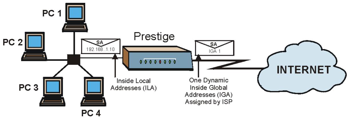
flowchart
graph LR
    PC1["PC 1"] -->|SA 192.168..1.10| Prestige["Prestige"]
    PC2["PC 2"] -->|SA 192.168..1.10| Prestige
    PC3["PC 3"] -->|SA 192.168..1.10| Prestige
    PC4["PC 4"] -->|SA 192.168..1.10| Prestige
    Prestige -->|Inside Local Addresses (ILA)| PC3
    Prestige -->|One Dynamic Inside Global Addresses (IGA) Assigned by ISP| SA1["SA IGA 1"]
    SA1 -->|INTERNET| Cloud["INTERNET"]
Figure 31-11 NAT Example 1
Menu 4 - Internet Access Setup
ISP's Name= MyISP
Encapsulation= RFC 1483
Multiplexing= LLC-based
VPI #= 8
VCI #= 35
ATM QoS Type= UBR
Peak Cell Rate (PCR)= 0
Sustain Cell Rate (SCR)= 0
Maximum Burst Size (MBS)= 0
My Login= N/A
My Password= N/A
ENET ENCAP Gateway= N/A
IP Address Assignment= Static
IP Address= 0.0.0.0
Network Address Translation= SUA Only
Address Mapping Set= N/A
Press ENTER to Confirm or ESC to Cancel:
Figure 31-12 Menu 4 Internet Access & NAT Example
From menu 4, choose the SUA Only option from the Network Address Translation field. This is the Many-to-One mapping discussed in section 31.5. The SUA Only read-only option from the Network Address Translation field in menus 4 and 11.3 is specifically pre-configured to handle this case.
31.5.2 Example 2: Internet Access with an Inside Server
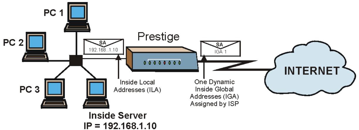
flowchart
graph TD
    PC1["PC 1"] -->|SA 192.168..1.10| Prestige["Prestige"]
    PC2["PC 2"] -->|SA 192.168..1.10| Prestige
    PC3["PC 3"] -->|SA 192.168..1.10| Prestige
    Prestige -->|Inside Local Addresses (ILA)| SA1["SA IGA 1"]
    Prestige -->|One Dynamic Inside Global Addresses (IGA) Assigned by ISP| SA2["SA IGA 1"]
    SA1 --> INTERNET["INTERNET"]
    SA2 --> INTERNET
    style INTERNET fill:#cce5ff,stroke:#333
Figure 31-13 NAT Example 2
In this case, you do exactly as above (use the convenient pre-configured SUA Only set) and also go to menu 15.2 to specify the Inside Server behind the NAT as shown in the next figure.
| Rule | Start Port No. | End Port No. | IP Address |
| 1. | Default | Default | 192.168.1.10 |
| 2. | 0 | 0 | 0.0.0.0 |
| 3. | 0 | 0 | 0.0.0.0 |
| 4. | 0 | 0 | 0.0.0.0 |
| 5. | 0 | 0 | 0.0.0.0 |
| 6. | 0 | 0 | 0.0.0.0 |
| 7. | 0 | 0 | 0.0.0.0 |
| 8. | 0 | 0 | 0.0.0.0 |
| 9. | 0 | 0 | 0.0.0.0 |
| 10. | 0 | 0 | 0.0.0.0 |
| 11. | 0 | 0 | 0.0.0.0 |
| 12. | 0 | 0 | 0.0.0.0 |
Figure 31-14 Menu 15.2.1 Specifying an Inside Server
31.5.3 Example 3: Multiple Public IP Addresses With Inside Servers
In this example, there are 3 IGAs from our ISP. There are many departments but two have their own FTP server. All departments share the same router. The example will reserve one IGA for each department with an FTP server and all departments use the other IGA. Map the FTP servers to the first two IGAs and the other LAN traffic to the remaining IGA. Map the third IGA to an inside web server and mail server. Four rules need to be configured, two bi-directional and two uni-directional as follows.
Rule 1. Map the first IGA to the first inside FTP server for FTP traffic in both directions (1 : 1 mapping, giving both local and global IP addresses).
Rule 2. Map the second IGA to our second inside FTP server for FTP traffic in both directions (1 : 1 mapping, giving both local and global IP addresses).
Rule 3. Map the other outgoing LAN traffic to IGA3 (Many : 1 mapping).
Rule 4. You also map your third IGA to the web server and mail server on the LAN. Type Server allows you to specify multiple servers, of different types, to other computers behind NAT on the LAN.
The example situation looks somewhat like this:
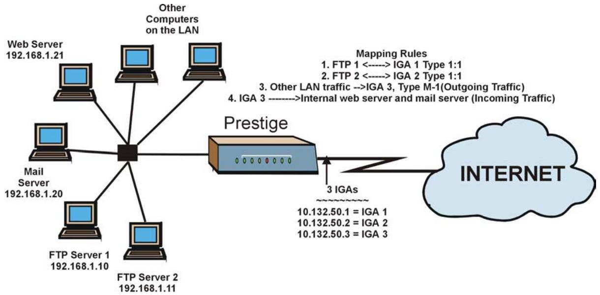
flowchart
graph TD
    A["Web Server 192.168.1.21"] --> B["Central Node"]
    C["Mail Server 192.168.1.20"] --> B
    D["FTP Server 1 192.168.1.10"] --> B
    E["FTP Server 2 192.168.1.11"] --> B
    F["Other Computers on the LAN"] --> B
    G["Prestige"] --> H["3 IGAs"]
    H --> I["INTERNET"]
    style I fill:#cce5ff,stroke:#333
    note right of B: Mapping Rules
    note left of B: 3. Other LAN traffic --> IGA1["IGA 1 Type 1:1"]
    note right of B: 4. IGA3["IGA 3"] --> IGA2["IGA 2 Type 1:1"]
    note right of B: 3. Other LAN traffic --> IGA3["IGA 3, Type M-1(Outgoing Traffic)"]
    note right of B: Internal web server and mail server (Incoming Traffic)
Figure 31-15 NAT Example 3
Step 1. In this case you need to configure Address Mapping Set 1 from Menu 15.1 - Address Mapping Sets. Therefore you must choose the Full Feature option from the Network Address Translation field (in menu 4 or menu 11.3) in Figure 31-16.
Step 2. Then enter 15 from the main menu.
Step 3. Enter 1 to configure the Address Mapping Sets.
Step 4. Enter 1 to begin configuring this new set. Enter a Set Name, choose the Edit Action and then enter 1 for the Select Rule field. Press [ENTER] to confirm.
Step 5. Select Type as One-to-One (direct mapping for packets going both ways), and enter the local Start IP as 192.168.1.10 (the IP address of FTP Server 1), the global Start IP as 10.132.50.1 (our first IGA). (See Figure 31-17).
Step 6. Repeat the previous step for rules 2 to 4 as outlined above.
Step 7. When finished, menu 15.1.1 should look like as shown in.
Menu 11.3 - Remote Node Network Layer Options
IP Options: Bridge Options:
IP Address Assignment= Static Ethernet Addr Timeout (min)= 0
Rem IP Addr: 0.0.0.0
Rem Subnet Mask= 0.0.0.0
My WAN Addr= 0.0.0.0
NAT= Full Feature
Address Mapping Set= 2
Metric= 2
Private= No
RIP Direction= Both
Version= RIP-2B
Multicast= IGMP-v2
IP Policies=
Press ENTER to Confirm or ESC to Cancel:
Figure 31-16 Example 3: Menu 11.3
The following figures show how to configure the first rule
Menu 15.1.1.1 Address Mapping Rule
Type= One-to-One
Local IP:
    Start= 192.168.1.10
    End = N/A
Global IP:
    Start= 10.132.50.1
    End = N/A
Server Mapping Set= N/A
Press ENTER to Confirm or ESC to Cancel:
Press Space Bar to Toggle.
Figure 31-17 Example 3: Menu 15.1.1.1
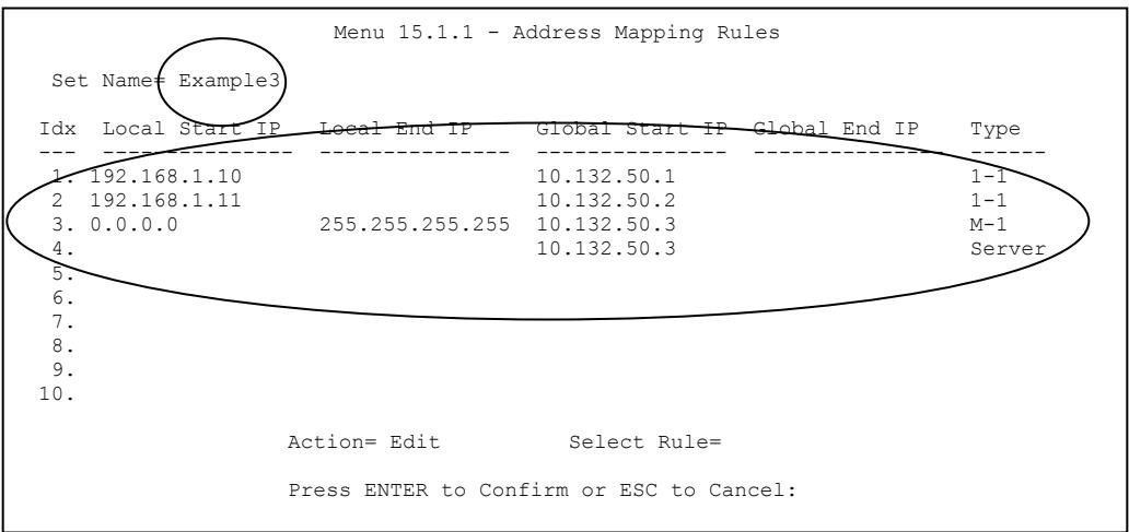
Figure 31-18 Example 3: Final Menu 15.1.1
Now configure the IGA3 to map to our web server and mail server on the LAN.
Step 8. Enter 15 from the main menu.
Step 9. Enter 2 in Menu 15 - NAT Setup.
Step 10. Enter 1 in Menu 15.2 - NAT Server Sets to see the following menu. Configure it as shown.
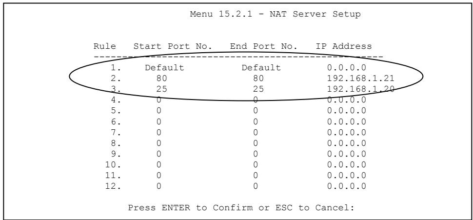
other
Menu 15.2.1 - NAT Server Setup | Rule | Start Port No. | End Port No. | IP Address | |---|---|---|---| | 1. | Default | Default | 0.0.0.0 | | 2. | 80 | 80 | 192.168.1.21 | | 3. | 25 | 25 | 192.168.1.20 | | 4. | 0 | 0 | 0.0.0.0 | | 5. | 0 | 0 | 0.0.0.0 | | 6. | 0 | 0 | 0.0.0.0 | | 7. | 0 | 0 | 0.0.0.0 | | 8. | 0 | 0 | 0.0.0.0 | | 9. | 0 | 0 | 0.0.0.0 | | 10. | 0 | 0 | 0.0.0.0 | | 11. | 0 | 0 | 0.0.0.0 | | 12. | 0 | 0 | 0.0.0.0 | Press ENTER to Confirm or ESC to Cancel:Example 3: Menu 15.2.1
31.5.4 Example 4: NAT Unfriendly Application Programs
Some applications do not support NAT Mapping using TCP or UDP port address translation. In this case it is better to use Many-to-Many No Overload mapping as port numbers do not change for Many-to-Many No Overload (and One-to-One) NAT mapping types. The following figure illustrates this.
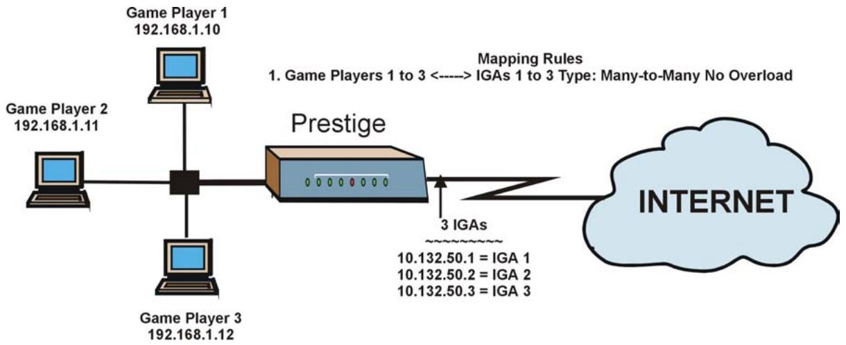
flowchart
graph LR
    A["Game Player 1\n192.168.1.10"] --> B["Computer"]
    C["Game Player 2\n192.168.1.11"] --> B
    D["Game Player 3\n192.168.1.12"] --> B
    B --> E["Prestige"]
    E --> F["3 IGAs\n10.132.50.1 = IGA 1\n10.132.50.2 = IGA 2\n10.132.50.3 = IGA 3"]
    G["INTERNET"] --> E
    style G fill:#cce5ff,stroke:#333
Figure 31-19 NAT Example 4
Other applications such as some gaming programs are NAT unfriendly because they embed addressing information in the data stream. These applications won't work through NAT even when using One-to-One and Many-to-Many No Overload mapping types.
Follow the steps outlined in example 3 to configure these two menus as follows.
Menu 15.1.1.1 Address Mapping Rule
Type= Many-to-Many No Overload
Local IP:
    Start= 192.168.1.10
    End = 192.168.1.12
Global IP:
    Start= 10.132.50.1
    End = 10.132.50.3
Server Mapping Set= N/A
Press ENTER to Confirm or ESC to Cancel:
Figure 31-20 Example 4: Menu 15.1.1.1 Address Mapping Rule
After you've configured your rule, you should be able to check the settings in menu 15.1.1 as shown next.
Menu 15.1.1 - Address Mapping Rules
Set Name= Example4
Idx Local Start IP Local End IP Global Start IP Global End IP Type
1. 192.168.1.10 192.168.1.12 10.132.50.1 10.132.50.3 M:M NO OV
2.
3.
4.
5.
6.
7.
8.
9.
10.
Action= Edit Select Rule=
Press ENTER to Confirm or ESC to Cancel:
Figure 31-21 Example 4: Menu 15.1.1 Address Mapping Rules
Chapter 32
Enabling the Firewall
This chapter shows you how to get started with the Prestige firewall.
32.1 Remote Management and the Firewall
When SMT menu 24.11 is configured to allow management (see the Remote Management chapter) and the firewall is enabled:
- The firewall blocks remote management from the WAN unless you configure a firewall rule to allow it.
• The firewall allows remote management from the LAN.
32.2 Access Methods
The web configurator is, by far, the most comprehensive firewall configuration tool your Prestige has to offer. For this reason, it is recommended that you configure your firewall using the web configurator, see the following chapters for instructions. SMT screens allow you to activate the firewall and view firewall logs.
32.3 Enabling the Firewall
From the main menu enter 21 to go to Menu 21 - Filter Set and Firewall Configuration to display the screen shown next.
Enter option 2 in this menu to bring up the following screen. Press [SPACE BAR] and then [ENTER] to select Yes in the Active field to activate the firewall. The firewall must be active to protect against Denial of Service (DoS) attacks. Additional rules may be configured using the web configurator.
Menu 21.2 - Firewall Setup
The firewall protects against Denial of Service (DOS) attacks when it is active. The default Policy sets
1. allow all sessions originating from the LAN to the WAN and
2. deny all sessions originating from the WAN to the LAN
You may define additional Policy rules or modify existing ones but please exercise extreme caution in doing so
Active: Yes
LAN-to-WAN Set Name: ACL Default Set
WAN-to-LAN Set Name: ACL Default Set
Please configure the Firewall function through Web Configurator.
Press ENTER to Confirm or ESC to Cancel:
Figure 32-1 Menu 21.2 Firewall Setup
Use the web configurator or the command interpreter to configure the firewall rules.
Part IX:
SMT Advanced Management
This part discusses filtering setup, SNMP, system security, system information and diagnosis, firmware and configuration file maintenance, system maintenance, remote management, IP Policy Routing and call scheduling.
See the web configurator parts of this guide for background information on features configurable by web configurator and SMT.
Chapter 33
Filter Configuration
This chapter shows you how to create and apply filters.
33.1 About Filtering
Your Prestige uses filters to decide whether or not to allow passage of a data packet and/or to make a call. There are two types of filter applications: data filtering and call filtering. Filters are subdivided into device and protocol filters, which are discussed later.
Data filtering screens data to determine if the packet should be allowed to pass. Data filters are divided into incoming and outgoing filters, depending on the direction of the packet relative to a port. Data filtering can be applied on either the WAN side or the Ethernet side. Call filtering is used to determine if a packet should be allowed to trigger a call.
Outgoing packets must undergo data filtering before they encounter call filtering. Call filters are divided into two groups, the built-in call filters and user-defined call filters. Your Prestige has built-in call filters that prevent administrative, for example, RIP packets from triggering calls. These filters are always enabled and not accessible to you. Your Prestige applies the built-in filters first and then the user-defined call filters, if applicable, as shown next.
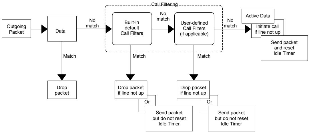
flowchart
graph TD
    A["Outgoing Packet"] --> B["Data"]
    B -->|Match| C["Drop packet"]
    B -->|No match| D["Built-in default Call Filters"]
    D -->|Match| E["Drop packet if line not up"]
    D -->|No match| F["User-defined Call Filters (if applicable)"]
    F -->|Match| G["Drop packet if line not up"]
    F -->|No match| H["Active Data"]
    H --> I["Initiate call if line not up"]
    I --> J["Send packet and reset Idle Timer"]
    D --> K["Send packet but do not reset Idle Timer"]
    F --> L["Send packet but do not reset Idle Timer"]
    style D fill:#f9f,stroke:#333
    style F fill:#f9f,stroke:#333
    style H fill:#ccf,stroke:#333
Figure 33-1 Outgoing Packet Filtering Process
Two sets of factory filter rules have been configured in menu 21 to prevent NetBIOS traffic from triggering calls. A summary of their filter rules is shown in the figures that follow.
The following figure illustrates the logic flow when executing a filter rule.
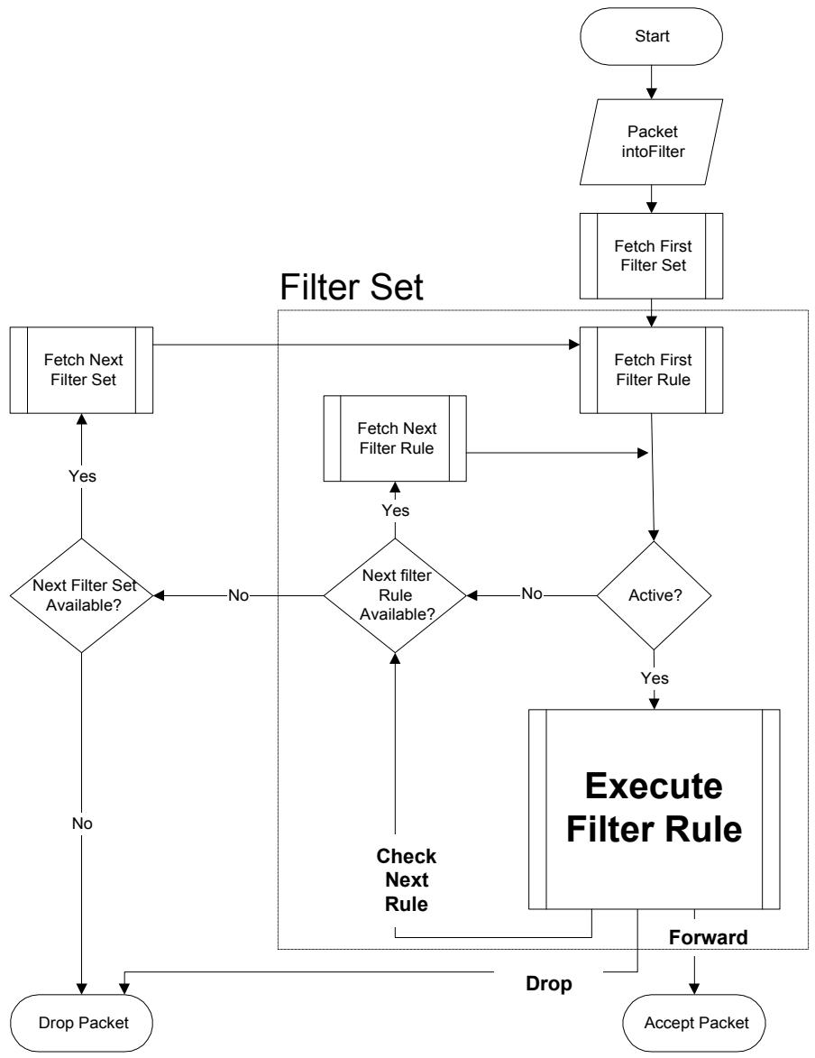
flowchart
graph TD
    A["Start"] --> B["Packet intoFilter"]
    B --> C["Fetch First Filter Set"]
    C --> D["Fetch First Filter Rule"]
    D --> E{Active?}
    E -->|Yes| F["Execute Filter Rule"]
    E -->|No| G{Next filter Rule Available?}
    G -->|Yes| H["Fetch Next Filter Set"]
    H --> I{Next Filter Set Available?}
    I -->|No| J["Drop Packet"]
    I -->|Yes| K["Check Next Rule"]
    K --> L["Receive"]
    L --> M["Accept Packet"]
    D --> N["Fetch Next Filter Rule"]
    N --> O["Fetch First Filter Set"]
    O --> P["Fetch First Filter Rule"]
    P --> Q["Receive"]
    Q --> R["Receive"]
    R --> S["Accept Packet"]
    style A fill:#f9f,stroke:#333
    style B fill:#ccf,stroke:#333
    style C fill:#cfc,stroke:#333
    style D fill:#fcc,stroke:#333
    style E fill:#cff,stroke:#333
    style F fill:#ffc,stroke:#333
    style G fill:#cfc,stroke:#333
    style H fill:#fcc,stroke:#333
    style I fill:#ffc,stroke:#333
    style J fill:#fcc,stroke:#333
    style K fill:#ffc,stroke:#333
    style L fill:#cfc,stroke:#333
    style M fill:#fcc,stroke:#333
    style N fill:#cfc,stroke:#333
    style O fill:#fcc,stroke:#333
    style P fill:#cfc,stroke:#333
    style Q fill:#fcc,stroke:#333
    style R fill:#cfc,stroke:#333
    style S fill:#fcc,stroke:#333
Figure 33-2 Filter Rule Process
You can apply up to four filter sets to a particular port to block various types of packets. Because each filter set can have up to six rules, you can have a maximum of 24 rules active for a single port.
For incoming packets, your Prestige applies data filters only. Packets are processed depending on whether a match is found. The following sections describe how to configure filter sets.
The Filter Structure of the Prestige
A filter set consists of one or more filter rules. Usually, you would group related rules, for example, all the rules for NetBIOS, into a single set and give it a descriptive name. You can configure up to twelve filter sets with six rules in each set, for a total of 72 filter rules in the system.
33.2 Configuring a Filter Set for the Prestige 652H/HW
To configure a filter set, follow the steps shown next.
Step 1. Enter 21 in the main menu to display Menu 21 – Filter and Firewall Setup.
Step 2. Enter 1 to display Menu 21.1 – Filter Set Configuration as shown next.
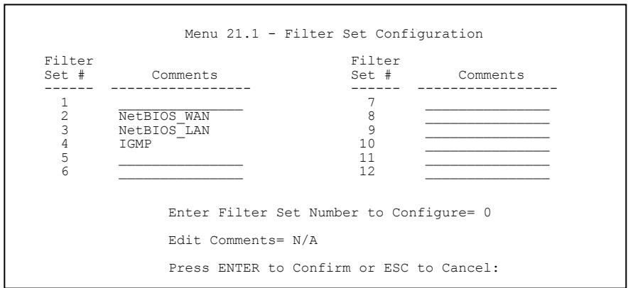
Figure 33-3 Menu 21 Filter Set Configuration (P652H/HW)
Step 3. Type the filter set to configure (no. 1 to 12) and press [ENTER].
Step 4. Type a descriptive name or comment in the Edit Comments field and press [ENTER].
Step 5. Press [ENTER] at the message “Press ENTER to confirm…” to display Menu 21.1.1 – Filter Rules Summary (that is, if you selected filter set 1 in menu 21.1).
| Menu 21.1.2 - Filter Rules Summary | |||
| # A Type | Filter Rules | M m n | |
| 1 Y IP | Pr=6, SA=0.0.0.0, DA=0.0.0.0, DP=137 | N D N | |
| 2 Y IP | Pr=6, SA=0.0.0.0, DA=0.0.0.0, DP=138 | N D N | |
| 3 Y IP | Pr=6, SA=0.0.0.0, DA=0.0.0.0, DP=139 | N D N | |
| 4 Y IP | Pr=17, SA=0.0.0.0, DA=0.0.0.0, DP=137 | N D N | |
| 5 Y IP | Pr=17, SA=0.0.0.0, DA=0.0.0.0, DP=138 | N D N | |
| 6 Y IP | Pr=17, SA=0.0.0.0, DA=0.0.0.0, DP=139 | N D F | |
| Enter Filter Rule Number (1-6) to Configure: | |||
Figure 33-4 NetBIOS_WAN Filter Rules Summary (P652H/HW)
| Menu 21.1.3 - Filter Rules Summary | |||
| # A Type | Filter Rules | M m n | |
| - - - - - - - - - - - - - - - - - - - - - - - - - - - - - - - - - - - - - - - - - - - - - - - - - - - - - - - - - - - - - - - - - - - - - - - - - - - - - - - - - - - - - - - - - | |||
| 1 Y IP | Pr=17, SA=0.0.0.0, SP=137, DA=0.0.0.0, DP=53 | N D F | |
| 2 N | |||
| 3 N | |||
| 4 N | |||
| 5 N | |||
| 6 N | |||
| Enter Filter Rule Number (1-6) to Configure: | |||
Figure 33-5 NetBIOS_LAN Filter Rules Summary (P652H/HW)
| Menu 21.1.4 - Filter Rules Summary | |||
| # A Type | Filter Rules | M m n | |
| - - | ---- | - - - | |
| 1 Y Gen | Off=0, Len=3, Mask=ffffff, Value=01005e | N D F | |
| 2 N | |||
| 3 N | |||
| 4 N | |||
| 5 N | |||
| 6 N | |||
| Enter Filter Rule Number (1-6) to Configure: | |||
Figure 33-6 IGMP Filter Rules Summary (P652H/HW)
33.3 Configuring a Filter Set for the Prestige 652
To configure a filter set, follow the steps shown next.
Step 1. Enter 21 in the main menu to display Menu 21 – Filter and Firewall Setup.
Step 2. Enter 1 to display Menu 21.1 – Filter Set Configuration as shown next.
| Menu 21.1 - Filter Set Configuration | |||
| Filter Set # | Comments | Filter Set # | Comments |
| 1 | 7 | ||
| 2 | NetBIOS_WAN | 8 | |
| 3 | NetBIOS_LAN | 9 | |
| 4 | PPPoE | 10 | |
| 5 | TEL_FTP_WEB_SNM | 11 | |
| 6 | 12 | ||
| Enter Filter Set Number to Configure= 0 | |||
| Edit Comments= N/A | |||
| Press ENTER to Confirm or ESC to Cancel: | |||
Figure 33-7 Menu 21 Filter Set Configuration (P652)
Step 3. Type the filter set to configure (no. 1 to 12) and press [ENTER].
Step 4. Type a descriptive name or comment in the Edit Comments field and press [ENTER].
Step 5. Press [ENTER] at the message “Press ENTER to confirm…” to display Menu 21.1.1 – Filter Rules Summary (that is, if you selected filter set 1 in menu 21.1).
See Figure 33-4 for the summary of the NetBIOS WAN rules and Figure 33-5 for the summary of the NetBIOS LAN rules.
| Menu 21.1.4 - Filter Rules Summary | |||
| # A Type | Filter Rules | M m n | |
| - - - - - - - - - - - - - - - - - - - - - - - - - - - - - - - - - - - - - - - - - - - - - - - - - - - - - - - - - - - - - - - - - - - - - - - - - - - - - - - - - - - - - - - - - - - - - - - - - - - - - | |||
| 1 Y Gen | Off=12, Len=2, Mask=ffff, Value=8863 | N F N | |
| 2 Y Gen | Off=12, Len=2, Mask=ffff, Value=8864 | N F D | |
| 3 N | |||
| 4 N | |||
| 5 N | |||
| 6 N | |||
| Enter Filter Rule Number (1-6) to Configure: | |||
Figure 33-8 PPPoE Filter Rules Summary (P652)
| Menu 21.1.5 - Filter Rules Summary | |||
| # A Type | Filter Rules | M m n | |
| - - - - - - - - - - - - - - - - - - - - - - - - - - - - - - - - - - - - - - - - - - - - - - - - - - - - - - - - - - - - - - - - - - - - - - - - - - - - - - - - - - - - - - - - - - - - - - - - - - - - - | |||
| 1 Y IP | Pr=6, SA=0.0.0.0, DA=0.0.0.0, DP=23 | N D N | |
| 2 Y IP | Pr=6, SA=0.0.0.0, DA=0.0.0.0, DP=21 | N D N | |
| 3 Y IP | Pr=6, SA=0.0.0.0, DA=0.0.0.0, DP=80 | N D N | |
| 4 Y IP | Pr=17, SA=0.0.0.0, DA=0.0.0.0, DP=69 | N D N | |
| 5 Y IP | Pr=17, SA=0.0.0.0, DA=0.0.0.0, DP=161 | N D N | |
| 6 Y IP | Pr=17, SA=0.0.0.0, DA=0.0.0.0, DP=162 | N D F | |
| Enter Filter Rule Number (1-6) to Configure: | |||
Figure 33-9 TEL_FTP_WEB_SNM Filter Rules Summary (P652)
33.4 Filter Rules Summary Menus
The following tables briefly describe the abbreviations used in menus 21.1.1 and 21.1.2.
Table 33-1 Abbreviations Used in the Filter Rules Summary Menu
| FIELD | DESCRIPTION |
| # | The filter rule number: 1 to 6. |
| A | Active: “Y” means the rule is active. “N” means the rule is inactive. |
| Type | The type of filter rule: “GEN” for Generic, “IP” for TCP/IP. |
| Filter Rules | These parameters are displayed here. |
Table 33-1 Abbreviations Used in the Filter Rules Summary Menu
| FIELD | DESCRIPTION |
| M | More.“Y” means there are more rules to check which form a rule chain with the present rule. An action cannot be taken until the rule chain is complete.“N” means there are no more rules to check. You can specify an action to be taken for instance, forward the packet, drop the packet or check the next rule. For the latter, the next rule is independent of the rule just checked. |
| m | Action Matched.“F” means to forward the packet immediately and skip checking the remaining rules.“D” means to drop the packet.“N” means to check the next rule. |
| n | Action Not Matched.“F” means to forward the packet immediately and skip checking the remaining rules.“D” means to drop the packet.“N” means to check the next rule. |
The protocol dependent filter rules abbreviation are listed as follows:
Table 33-2 Rule Abbreviations Used
| FILTER TYPE | DESCRIPTION |
| IP | |
| Pr | Protocol |
| SA | Source Address |
| SP | Source Port Number |
| DA | Destination Address |
| DP | Destination Port Number |
| GEN | |
| Off | Offset |
| Len | Length |
33.5 Configuring a Filter Rule
To configure a filter rule, type its number in Menu 21.1.x – Filter Rules Summary and press [ENTER] to open menu 21.1.x.1 for the rule.
There are two types of filter rules: TCP/IP and Generic. Depending on the type of rule, the parameters for each type will be different. Use [SPACE BAR] to select the type of rule that you want to create in the Filter Type field and press [ENTER] to open the respective menu.
To speed up filtering, all rules in a filter set must be of the same class, for instance, protocol filters or generic filters. The class of a filter set is determined by the first rule that you create. When applying the filter sets to a port, separate menu fields are provided for protocol and device filter sets. If you include a protocol filter set in a device filters field or vice versa, the Prestige will warn you and will not allow you to save.
33.5.1 TCP/IP Filter Rule
This section shows you how to configure a TCP/IP filter rule. TCP/IP rules allow you to base the rule on the fields in the IP and the upper layer protocol, for example, UDP and TCP headers.
To configure TCP/IP rules, select TCP/IP Filter Rule from the Filter Type field and press [ENTER] to open Menu 21.1.x.1 – TCP/IP Filter Rule, as shown next.
Menu 21.1.1.1 - TCP/IP Filter Rule
Filter #: 1,1
Filter Type= TCP/IP Filter Rule
Active= No
IP Protocol= 0    IP Source Route= No
Destination: IP Addr=
    IP Mask=
    Port #=
    Port # Comp= None
Source: IP Addr=
    IP Mask=
    Port #=
    Port # Comp= None
TCP Estab= N/A
More= No    Log= None
Action Matched= Check Next Rule
Action Not Matched= Check Next Rule
Press ENTER to Confirm or ESC to Cancel:
Press Space Bar to Toggle.
Figure 33-10 Menu 21.1.x.1 TCP/IP Filter Rule
The following table describes how to configure your TCP/IP filter rule.
Table 33-3 Menu 21.1.x.1 TCP/IP Filter Rule
| FIELD | DESCRIPTION | EXAMPLE |
| Filter # | This is the filter set, filter rule coordinates, for instance, 2, 3 refers to the second filter set and the third filter rule of that set. | 1,1 |
| Filter Type | Use [SPACE BAR] and then [ENTER] to choose a rule. Parameters displayed for each type will be different.Choices are TCP/IP Filter Rule or Generic Filter Rule. | TCP/IP Filter Rule |
| Active | Select Yes to activate or No to deactivate the filter rule. | No (default) |
| IP Protocol | This is the upper layer protocol, for example, TCP is 6, UDP is 17 and ICMP is 1. The value must be between 0 and 255. A value of O matches ANY protocol. | 0 to 255 |
| IP Source Route | IP Source Route is an optional header that dictates the route an IP packet takes from its source to its destination. If Yes, the rule applies to any packet with an IP source route. The majority of IP packets do not have source route. | No (default) |
| Destination:IP Addr | Type the destination IP address of the packet you want to filter. This field is ignored if it is 0.0.0.0. | IP address |
| IP Mask | Type the IP mask to apply to the Destination: IP Addr field. | IP mask |
| Port # | Type the destination port of the packets you want to filter. The field range is 0 to 65535. A 0 field is ignored. | 0 to 65535 |
| Port # Comp | Select the comparison to apply to the destination port in the packet against the value given in Destination: Port #. Choices are None, Less, Greater, Equal or Not Equal. | None |
| Source:IP Addr | Type the source IP Address of the packet you want to filter. A 0.0.0.0 field is ignored. | IP address |
| IP Mask | Type the IP mask to apply to the Source: IP Addr field. | IP mask |
| Port # | Type the source port of the packets you want to filter. The range of this field is 0 to 65535. A 0 field is ignored. | 0 to 65535 |
| Port # Comp | Select the comparison to apply to the source port in the packet against the value given in Source: Port # field. Choices are None, Less, Greater, Equal or Not Equal. | None |
Table 33-3 Menu 21.1.x.1 TCP/IP Filter Rule
| FIELD | DESCRIPTION | EXAMPLE |
| TCP Estab | This applies only when the IP Protocol field is 6, TCP. If Yes, the rule matches packets that want to establish TCP connection(s) (SYN=1 and ACK=0); else it is ignored. | No (default) |
| More | If Yes, a matching packet is passed to the next filter rule before an action is taken or else the packet is disposed of according to the action fields.If More is Yes, then Action Matched and Action Not Matched will be N/A. | No (default) |
| Log | Select the logging option from the following:None – No packets will be logged.Action Matched – Only packets that match the rule parameters will be logged.Action Not Matched – Only packets that do not match the rule parameters will be logged.Both – All packets will be logged. | None |
| Action Matched | Select the action for a matching packet. Choices are Check Next Rule, Forward or Drop. | Check Next Rule (default) |
| Action Not Matched | Select the action for a packet not matching the rule.Choices are Check Next Rule, Forward or Drop. | Check Next Rule (default) |
| When you have completed this menu, press [ENTER] at the prompt “Press ENTER to confirm or ESC to cancel” to save your configuration or press [ESC] to cancel and go back to the previous screen. | ||
The following figure illustrates the logic flow of an IP filter.

flowchart
graph TD
    A["Packet into IP Filter"] --> B{Filter Active?}
    B -->|Yes| C["Apply SrcAddrMask to Src Addr"]
    C --> D{Check Src IP Addr}
    D -->|Matched| E["Apply DestAddrMask to Dest Addr"]
    E --> F{Check Dest IP Addr}
    F -->|Matched| G{Check IP Protocol}
    G -->|Matched| H{Check Src & Dest Port}
    H -->|Matched| I{More?}
    I -->|No| J["Action Matched"]
    I -->|Yes| K["Action Not Matched"]
    J --> L["Drop Packet"]
    K --> M["Accept Packet"]
    L --> N["Check Next Rule"]
    M --> N
    N --> O["Forward"]
    O --> K
    D -->|Not Matched| P["Action Not Matched"]
    F -->|Not Matched| Q["Action Not Matched"]
    G -->|Not Matched| R["Action Not Matched"]
    H -->|Not Matched| S["Action Not Matched"]
    I -->|Yes| T["Action Not Matched"]
    T --> U["Drop"]
    U --> V["Drop Packet"]
    T --> W["Check Next Rule"]
    W --> X["Forward"]
    X --> Y["Accept Packet"]
Figure 33-11 Executing an IP Filter
33.5.2 Generic Filter Rule
This section shows you how to configure a generic filter rule. The purpose of generic rules is to allow you to filter non-IP packets. For IP, it is generally easier to use the IP rules directly.
For generic rules, the Prestige treats a packet as a byte stream as opposed to an IP packet. You specify the portion of the packet to check with the Offset (from 0) and the Length fields, both in bytes. The Prestige applies the Mask (bit-wise ANDing) to the data portion before comparing the result against the Value to determine a match. The Mask and Value fields are specified in hexadecimal numbers. Note that it takes two hexadecimal digits to represent a byte, so if the length is 4, the value in either field will take 8 digits, for example, FFFFFFFF.
To configure a generic rule select an empty filter set in menu 21, for example 5. Select Generic Filter Rule in the Filter Type field and press [ENTER] to open Menu 21.1.5.1 – Generic Filter Rule, as shown in the following figure.
Menu 21.1.5.1 - Generic Filter Rule
Filter #: 5,1
Filter Type= Generic Filter Rule
Active= No
Offset= 0
Length= 0
Mask= N/A
Value= N/A
More= No Log= None
Action Matched= Check Next Rule
Action Not Matched= Check Next Rule
Press ENTER to Confirm or ESC to Cancel:
Press Space Bar to Toggle.
Figure 33-12 Menu 21.1.5.1 Generic Filter Rule
The next table describes the fields in the Generic Filter Rule menu.
Table 33-4 Menu 21.1.5.1 Generic Filter Rule
| FIELD | DESCRIPTION | EXAMPLE |
| Filter # | This is the filter set, filter rule coordinates, for instance, 2, 3 refers to the second filter set and the third rule of that set. | 5,1 |
| Filter Type | Press [SPACE BAR] and then [ENTER] to select a type of rule.Parameters displayed below each type will be different. Choices are Generic Filter Rule or TCP/IP Filter Rule. | Generic Filter Rule |
| Active | Select Yes to turn on or No to turn off the filter rule. | No (default) |
| Offset | Type the starting byte of the data portion in the packet that you want to compare. The range for this field is from 0 to 255. | 0 (default) |
| Length | Type the byte count of the data portion in the packet that you want to compare. The range for this field is 0 to 8. | 0 (default) |
| Mask | Type the mask (in Hexadecimal) to apply to the data portion before comparison. | |
| Value | Type the value (in Hexadecimal) to compare with the data portion. | |
| More | If Yes, a matching packet is passed to the next filter rule before an action is taken or else the packet is disposed of according to the action fields.If More is Yes, then Action Matched and Action Not Matched will be N/A. | No (default) |
| Log | Select the logging option from the following:None – No packets will be logged.Action Matched – Only matching packets and rules will be logged.Action Not Matched – Only packets that do not match the rule parameters will be logged.Both – All packets will be logged. | None |
| Action Matched | Select the action for a matching packet. Choices are Check Next Rule, Forward or Drop. | Check Next Rule (default) |
| Action Not Matched | Select the action for a packet not matching the rule. Choices are Check Next Rule, Forward or Drop. | Check Next Rule (default) |
| When you have completed this menu, press [ENTER] at the prompt “Press ENTER to confirm or ESC to cancel” to save your configuration or press [ESC] to cancel and go back to the previous screen. | ||
33.6 Filter Types and NAT
There are two classes of filter rules, Generic Filter Device rules and Protocol Filter (TCP/IP) rules. Generic Filter rules act on the raw data from/to LAN and WAN. Protocol Filter rules act on IP packets.
When NAT (Network Address Translation) is enabled, the inside IP address and port number are replaced on a connection-by-connection basis, which makes it impossible to know the exact address and port on the wire. Therefore, the Prestige applies the protocol filters to the “native” IP address and port number before NAT for outgoing packets and after NAT for incoming packets. On the other hand, the generic (or device) filters are applied to the raw packets that appear on the wire. They are applied at the point where the Prestige is receiving and sending the packets; for instance, the interface. The interface can be an Ethernet, or any other hardware port. The following figure illustrates this.
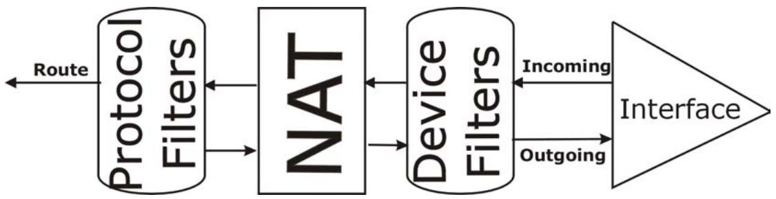
flowchart
graph LR
    A["Protocol Filters"] --> B["NAT"]
    B --> C["Device Filters"]
    C --> D["Interface"]
    A <-->|Route| A
    B <-->|Incoming| C
    C <-->|Outgoing| D
Figure 33-13 Protocol and Device Filter Sets
33.7 Example Filter
Let's look at an example to block outside users from telnetting into the Prestige.
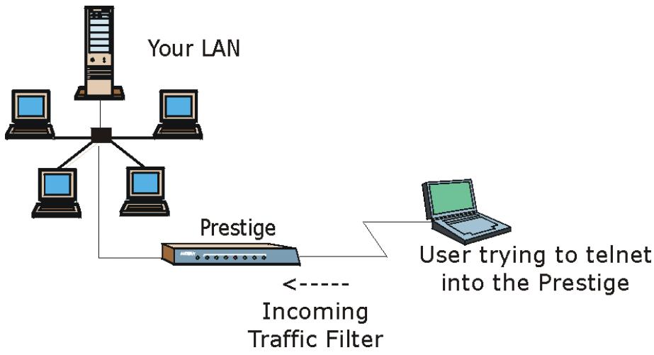
flowchart
graph TD
    A["User"] --> B["Your LAN"]
    B --> C["Computer 1"]
    B --> D["Computer 2"]
    B --> E["Computer 3"]
    B --> F["Prestige"]
    F --> G["Incoming Traffic Filter"]
    G --> H["User trying to telnet into the Prestige"]
Figure 33-14 Sample Telnet Filter
Step 1. Enter 1 in the menu 21 to display Menu 21.1 — Filter Set Configuration.
Step 2. Enter the index number of the filter set you want to configure (in this case 6).
Step 3. Type a descriptive name or comment in the Edit Comments field (for example, TELNET_WAN) and press [ENTER].
Step 4. Press [ENTER] at the message “Press [ENTER] to confirm or [ESC] to cancel” to open Menu 21.1.6 — Filter Rules Summary.
Step 5. Type 1 to configure the first filter rule. Make the entries in this menu as shown next.
When you press [ENTER] to confirm, the following screen appears. Note that there is only one filter rule in this set.
![Menu 21.1.6.1 - TCP/IP Filter Rule Filter #: 6,1 Filter Type= TCP/IP Filter Rule Active= Yes IP Protocol= 6 IP Source Route= No Destination: IP Addr= 0.0.0.0 IP Mask= 0.0.0.0 Port # = 23 Port # Comp= Equal Source: IP Addr= 0.0.0.0 IP Mask= 0.0.0.0 Port # Port # Comp= Equal TCP Estab= No More= No Log= None Action Matched= Drop Action Not Matched= Forward Press ENTER to Confirm or ESC to Cancel: There are no more rules to check. Select Drop here so that the packet will be dropped if its destination is the telnet port. Select Equal here as we are looking for packets going to port 23 only. Select Forward here so that the packet will be forwarded if its destination is not the telnet port and there are no more rules in this filter set to check. Select Next if there are more rules to check. Press [SPACE BAR] to choose this filter rule type. The first filter rule type determines all subsequent filter types within a set. Select Yes to make the rule active. 6 is the TCP protocol. The port number for the telnet service (TCP protocol) is 23. See RFC-1060 for port numbers of well- known services.](/content/2025/01/165353/images/71d3f55f3e1249cce57684cae1ff90f4de1ee5977662e2cde2ac83e077f09c0d.jpg)
Figure 33-15 Menu 21.1.6.1 Sample Filter
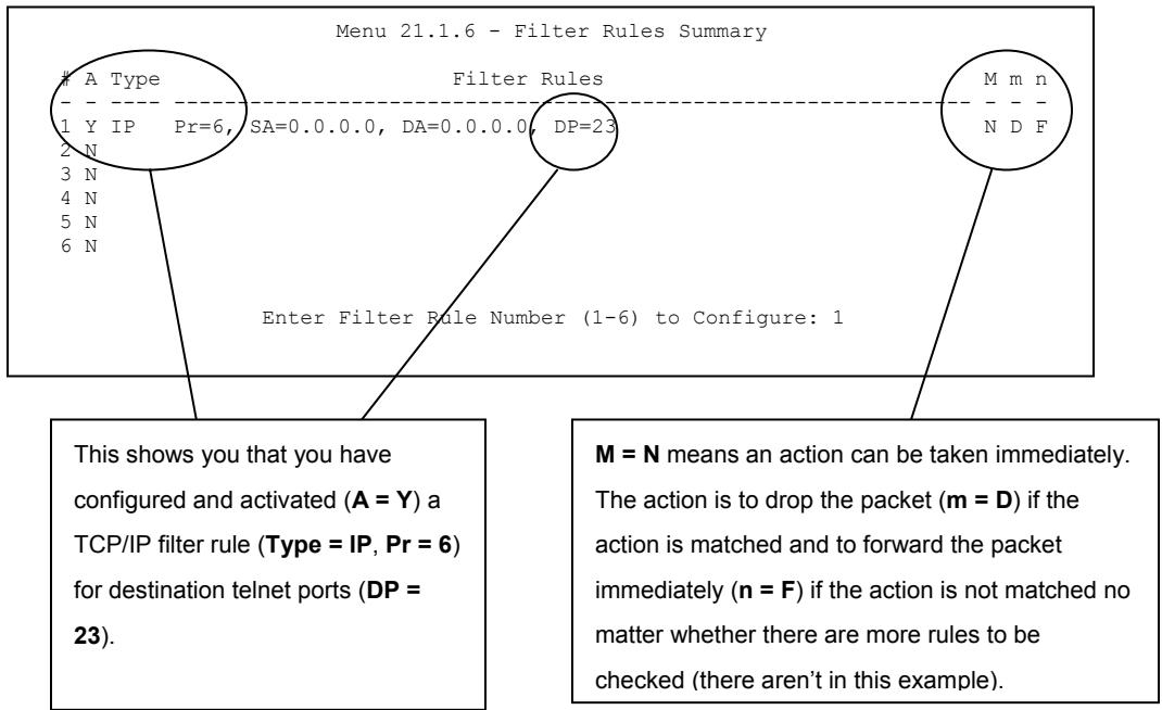
Figure 33-16 Menu 21.1.6.1 Sample Filter Rules Summary
After you have created the filter set, you must apply it.
Step 1. Enter 11 in the main menu to display menu 11 and type the remote node number to edit.
Step 2. Go to the Edit Filter Sets field, press [SPACE BAR] to choose Yes and press [ENTER].
Step 3. This brings you to menu 11.5. Apply the example filter set (for example, filter set 3) in this menu as shown in the next section.
33.8 Applying Filters and Factory Defaults
This section shows you where to apply the filter(s) after you design it (them). Sets of factory default filter rules have been configured in menu 21 (but have not been applied) to filter traffic.
Table 33-5 Filter Sets Table
| FILTER SETS | DESCRIPTION |
| Input Filter Sets: | Apply filters for incoming traffic. You may apply protocol or device filter rules. See earlier in this chapter for information on filters. |
| Output Filter Sets: | Apply filters for traffic leaving the Prestige. You may apply filter rules for protocol or device filters. See earlier in this section for information on types of filters. |
| Call Filter Sets: | Apply filters to decide if a packet should be allowed to trigger a call. |
33.8.1 Ethernet Traffic
You seldom need to filter Ethernet traffic; however, the filter sets may be useful to block certain packets, reduce traffic and prevent security breaches. Go to menu 3.1 (shown next) and type the number(s) of the filter set(s) that you want to apply as appropriate. You can choose up to four filter sets (from twelve) by typing their numbers separated by commas, for example, 3, 4, 6, 11. The factory default filter set, NetBIOS_LAN, is inserted in the protocol filters field under Input Filter Sets in menu 3.1 in order to prevent local NetBIOS messages from triggering calls to the DNS server.
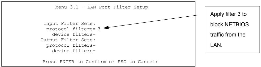
Figure 33-17 Filtering Ethernet Traffic
33.8.2 Remote Node Filters
Go to menu 11.5 (shown next) and type the number(s) of the filter set(s) as appropriate. You can cascade up to four filter sets by typing their numbers separated by commas. The factory default filter set,
NetBIOS_WAN, is inserted in the protocol filters field under Call Filter Sets in menu 11.5 to block local NetBIOS traffic from triggering calls to the ISP.
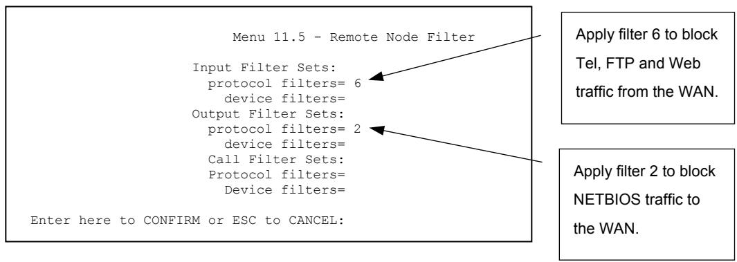
Figure 33-18 Filtering Remote Node Traffic
Note that call filter sets are visible when you select PPPoA or PPPoE encapsulation.
Chapter 34
SNMP Configuration
This chapter explains SNMP Configuration menu 22.
34.1 About SNMP
Simple Network Management Protocol is a protocol used for exchanging management information between network devices. SNMP is a member of the TCP/IP protocol suite. Your Prestige supports SNMP agent functionality, which allows a manager station to manage and monitor the Prestige through the network. The Prestige supports SNMP version one (SNMPv1) and version two c (SNMPv2c). The next figure illustrates an SNMP management operation. SNMP is only available if TCP/IP is configured.
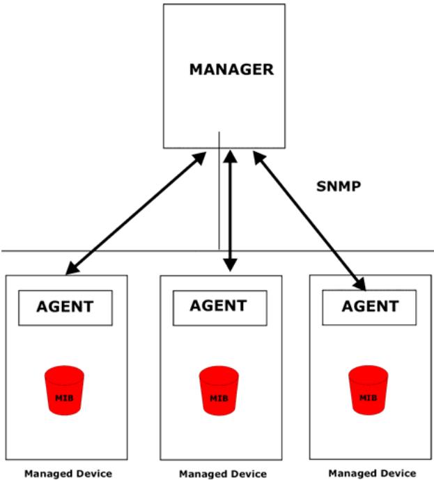
flowchart
graph TD
    A["MANAGER"] --> B["AGENT"]
    A --> C["AGENT"]
    A --> D["AGENT"]
    B --> E["MIB"]
    C --> F["MIB"]
    D --> G["MIB"]
    style A fill:#f9f,stroke:#333
    style B fill:#ccf,stroke:#333
    style C fill:#ccf,stroke:#333
    style D fill:#ccf,stroke:#333
    linkStyle 0 stroke:#000,stroke-width:2px
    linkStyle 1 stroke:#000,stroke-width:2px
    linkStyle 2 stroke:#000,stroke-width:2px
    linkStyle 3 stroke:#000,stroke-width:2px
    linkStyle 4 stroke:#000,stroke-width:2px
    linkStyle 5 stroke:#000,stroke-width:2px
    linkStyle 6 stroke:#000,stroke-width:2px
    linkStyle 7 stroke:#000,stroke-width:2px
    linkStyle 8 stroke:#000,stroke-width:2px
    linkStyle 9 stroke:#000,stroke-width:2px
    linkStyle 10 stroke:#000,stroke-width:2px
    linkStyle 11 stroke:#000,stroke-width:2px
    linkStyle 12 stroke:#000,stroke-width:2px
    linkStyle 13 stroke:#000,stroke-width:2px
    linkStyle 14 stroke:#000,stroke-width:2px
    linkStyle 15 stroke:#000,stroke-width:2px
    linkStyle 16 stroke:#000,stroke-width:2px
    linkStyle 17 stroke:#000,stroke-width:2px
    linkStyle 18 stroke:#000,stroke-width:2px
    linkStyle 19 stroke:#000,stroke-width:2px
    linkStyle 20 stroke:#000,stroke-width:2px
Figure 34-1 SNMP Management Model
An SNMP managed network consists of two main components: agents and a manager.
An agent is a management software module that resides in a managed device (the Prestige). An agent translates the local management information from the managed device into a form compatible with SNMP. The manager is the console through which network administrators perform network management functions. It executes applications that control and monitor managed devices.
The managed devices contain object variables/managed objects that define each piece of information to be collected about a device. Examples of variables include the number of packets received, node port status etc. A Management Information Base (MIB) is a collection of managed objects. SNMP allows a manager and agents to communicate for the purpose of accessing these objects.
SNMP itself is a simple request/response protocol based on the manager/agent model. The manager issues a request and the agent returns responses using the following protocol operations:
- Get - Allows the manager to retrieve an object variable from the agent.
- GetNext - Allows the manager to retrieve the next object variable from a table or list within an agent. In SNMPv1, when a manager wants to retrieve all elements of a table from an agent, it initiates a Get operation, followed by a series of GetNext operations.
- Set - Allows the manager to set values for object variables within an agent.
- Trap - Used by the agent to inform the manager of some events.
34.2 Supported MIBs
The Prestige supports RFC-1215 and MIB II as defined in RFC-1213 as well as ZyXEL private MIBs. The focus of the MIBs is to let administrators collect statistic data and monitor status and performance.
34.3 SNMP Configuration
To configure SNMP, select option 22 from the main menu to open Menu 22 — SNMP Configuration as shown next. The “community” for Get, Set and Trap fields is SNMP terminology for password.
Menu 22 - SNMP Configuration
SNMP:
Get Community= public
Set Community= public
Trusted Host= 0.0.0.0
Trap:
Community= public
Destination= 0.0.0.0
Press ENTER to Confirm or ESC to Cancel:
Figure 34-2 Menu 22 SNMP Configuration
The following table describes the SNMP configuration parameters.
Table 34-1 Menu 22 SNMP Configuration
| FIELD | DESCRIPTION | EXAMPLE |
| SNMP: | ||
| Get Community | Type the Get Community, which is the password for the incoming Get- and GetNext requests from the management station. | public |
| Set Community | Type the Set community, which is the password for incoming Set requests from the management station. | public |
| Trusted Host | If you enter a trusted host, your Prestige will only respond to SNMP messages from this address. A blank (default) field means your Prestige will respond to all SNMP messages it receives, regardless of source. | 0.0.0.0 |
| Trap: | ||
| Community | Type the trap community, which is the password sent with each trap to the SNMP manager. | public |
| Destination | Type the IP address of the station to send your SNMP traps to. | 0.0.0.0 |
| When you have completed this menu, press [ENTER] at the prompt “Press ENTER to confirm or ESC to cancel” to save your configuration or press [ESC] to cancel and go back to the previous screen. | ||
34.4 SNMP Traps
The Prestige will send traps to the SNMP manager when any one of the following events occurs:
Table 34-2 SNMP Traps
| TRAP # | TRAP NAME | DESCRIPTION |
| 1 | coldStart (defined in RFC-1215) | A trap is sent after booting (power on). |
| 2 | warmStart (defined in RFC-1215) | A trap is sent after booting (software reboot). |
| 3 | linkDown (defined in RFC-1215) | A trap is sent with the port number when any of the links are down. See the following table. |
| 4 | linkUp (defined in RFC-1215) | A trap is sent with the port number. |
| 5 | authenticationFailure (defined in RFC-1215) | A trap is sent to the manager when receiving any SNMP get or set requirements with wrong community (password). |
| 6 | whyReboot (defined in ZYXEL-MIB) | A trap is sent with the reason of restart before rebooting when the system is going to restart (warm start). |
| 6a | For intentional reboot : | A trap is sent with the message "System reboot by user!" if reboot is done intentionally, (for example, download new files, CI command "sys reboot", etc.). |
The port number is its interface index under the interface group.
Table 34-3 Ports and Permanent Virtual Circuits
| PORT | PVC (PERMANENT VIRTUAL CIRCUIT) |
| 1 | Ethernet LAN |
| 2 | 1 |
| 3 | 2 |
| ... | ... |
| 13 | 12 |
| 14 | xDSL |
Chapter 35
System Security
This chapter describes how to configure the system security on the Prestige. This chapter only applies to the P652H/HW.
35.1 System Security
You can configure the system password, an external RADIUS server and IEEE802.1x in menu 23.
35.1.1 System Password
Enter 23 in the main menu to display Menu 23 – System Security.
You should change the default password. If you forget your password you have to restore the default configuration file. Refer to the section on changing the system password in the Introducing the SMT chapter and the section on resetting the Prestige in the Introducing the Web Configurator chapter.
Menu 23 - System Security
1. Change Password
2. RADIUS Server
4. IEEE802.1x
Figure 35-1 Menu 23 System Security
35.1.2 Configuring External RADIUS Server
From Menu 23- System Security, enter 2 to display Menu 23.2 - System Security-RADIUS Server.
Menu 23 - System Security
1. Change Password
2. RADIUS Server
4. IEEE802.1x
Figure 35-2 Menu 23 System Security
Menu 23.2 - System Security - RADIUS Server
Authentication Server:
Active= No
Server Address= 10.11.12.13
Port #= 1812
Shared Secret= *****
Accounting Server:
Active= No
Server Address= 10.11.12.13
Port #= 1813
Shared Secret= *****
Press ENTER to Confirm or ESC to Cancel:
Figure 35-3 Menu 23.2 System Security : RADIUS Server
The following table describes the fields in this menu.
Table 35-1 Menu 23.2 System Security : RADIUS Server
| FIELD | DESCRIPTION | EXAMPLE |
| Authentication Server | ||
| Active | Press [SPACE BAR] to select Yes and press [ENTER] to enable user authentication through an external authentication server. | No |
| Server Address | Enter the IP address of the external authentication server in dotted decimal notation. | 10.11.12.13 |
| Port | The default port of the RADIUS server for authentication is 1812.You need not change this value unless your network administrator instructs you to do so with additional information. | 1812 |
| Shared Secret | Specify a password (up to 31 alphanumeric characters) as the key to be shared between the external authentication server and the access points.The key is not sent over the network. This key must be the same on the external authentication server and Prestige. | |
| Accounting Server | ||
| Active | Press [SPACE BAR] to select Yes and press [ENTER] to enable user authentication through an external accounting server. | No |
| Server Address | Enter the IP address of the external accounting server in dotted decimal notation. | 10.11.12.13 |
Table 35-1 Menu 23.2 System Security : RADIUS Server
| FIELD | DESCRIPTION | EXAMPLE |
| Port | The default port of the RADIUS server for accounting is 1813.You need not change this value unless your network administrator instructs you to do so with additional information. | 1813 |
| Shared Secret | Specify a password (up to 31 alphanumeric characters) as the key to be shared between the external accounting server and the access points.The key is not sent over the network. This key must be the same on the external accounting server and Prestige. | |
| When you have completed this menu, press [ENTER] at the prompt “Press ENTER to confirm or ESC to cancel” to save your configuration or press [ESC] to cancel and go back to the previous screen. | ||
35.1.3 IEEE802.1x
The IEEE802.1x standards outline enhanced security methods for both the authentication of wireless stations and encryption key management.
Follow the steps below to enable EAP authentication on your Prestige.
Step 1. From the main menu, enter 23 to display Menu23 – System Security.
Menu 23 - System Security
- Change Password
- RADIUS Server
- IEEE802.1x
Figure 35-4 Menu 23 System Security
Step 2. Enter 4 to display Menu 23.4 – System Security – IEEE802.1x.
Menu 23.4 - System Security - IEEE802.1x
Wireless Port Control= Authentication Required
ReAuthentication Timer (in second)= 1800
Idle Timeout (in second)= 3600
Authentication Databases= Local User Database Only
Press ENTER to Confirm or ESC to Cancel:
Figure 35-5 Menu 23.4 System Security : IEEE802.1x
The following table describes the fields in this menu.
Table 35-2 Menu 23.4 System Security : IEEE802.1x
| FIELD | DESCRIPTION |
| Wireless Port Control | Press [SPACE BAR] and select a security mode for the wireless LAN access.SelectNo Authentication Requiredto allow any clients access to your wired network without entering usernames and passwords. This is the default setting.SelectingAuthentication Requiredmeans clients have to enter usernames and passwords before access to the wired network is allowed.SelectNo Access Allowedto block all clients access to the wired network. |
| ReAuthentication Timer (in seconds) | Specify how often a client has to re-enter username and password to stay connected to the wired network.This field is activated only when you selectAuthentication Requiredin the Wireless Port Controlfield. Enter a time interval between 10 and 9999 (in seconds). The default time interval is1800seconds (or 30 minutes). |
| Idle Timeout | The Prestige automatically disconnects a client from the wired network after a period of inactivity. The client needs to enter the username and password again before access to the wired network is allowed.This field is activated only when you selectAuthentication Requiredin the Wireless Port Controlfield. The default time interval is3600seconds (or 1 hour). |
Table 35-2 Menu 23.4 System Security : IEEE802.1x
| FIELD | DESCRIPTION |
| Authentication Databases | This field is activated only when you select Authentication Required in the Wireless Port Control field.The authentication database contains wireless station login information. The local user database is the built-in database on the Prestige. The RADIUS is an external server. Use this field to decide which database the Prestige should use (first) to authenticate a wireless station.Before you specify the priority, make sure you have set up the corresponding database correctly first.Select Local User Database Only to have the Prestige just check the built-in user database on the Prestige for a wireless station's username and password.Select RADIUS Only to have the Prestige just check the user database on the specified RADIUS server for a wireless station's username and password.Select Local first, then RADIUS to have the Prestige first check the user database on the Prestige for a client's user name and password. If the user name is not found, the Prestige checks the user database on the specified RADIUS server.Select RADIUS first, then Local to have the Prestige first check the user database on the specified RADIUS server for a client's user name and password. When the user name is not found or password does not match in the RADIUS server, the Prestige will not check the local user database and the authentication fails. If the Prestige cannot reach the RADIUS server, then the Prestige checks the local user database on the Prestige. |
| When you have completed this menu, press [ENTER] at the prompt “Press ENTER to confirm or ESC to cancel” to save your configuration or press [ESC] to cancel and go back to the previous screen. | |
Once you enable user authentication, you need to specify an external RADIUS server or create local user accounts on the Prestige for authentication.
35.2 Creating User Accounts on the Prestige
By storing user profiles locally, your Prestige is able to authenticate wireless users without interacting with a network RADIUS server.
Follow the steps below to set up user profiles on your Prestige.
Step 2. From the main menu, enter 14 to display Menu 14 - Dial-in User Setup.
| Menu 14 - Dial-in User Setup | |||
| 1. _____ | 9. _____ | 17. _____ | 25. _____ |
| 2. _____ | 10. _____ | 18. _____ | 26. _____ |
| 3. _____ | 11. _____ | 19. _____ | 27. _____ |
| 4. _____ | 12. _____ | 20. _____ | 28. _____ |
| 5. _____ | 13. _____ | 21. _____ | 29. _____ |
| 6. _____ | 14. _____ | 22. _____ | 30. _____ |
| 7. _____ | 15. _____ | 23. _____ | 31. _____ |
| 8. _____ | 16. _____ | 24. _____ | 32. _____ |
| Enter Menu Selection Number: | |||
Figure 35-6 Menu 14 Dial-in User Setup
Step 3. Type a number and press [ENTER] to edit the user profile.
| Menu 14.1 - Edit Dial-in User |
| User Name= test Active= Yes Password= ********* |
| Press ENTER to Confirm or ESC to Cancel: |
Figure 35-7 Menu 14.1 Edit Dial-in User
The following table describes the fields in this menu.
Table 35-3 Menu 14.1 Edit Dial-in User
| FIELD | DESCRIPTION |
| User Name | Enter a username up to 31 alphanumeric characters long for this user profile.This field is case sensitive. |
| Active | Press [SPACE BAR] to select Yes and press [ENTER] to enable the user profile. |
| Password | Enter a password up to 31 characters long for this user profile. |
| When you have completed this menu, press [ENTER] at the prompt “Press ENTER to confirm or ESC to cancel” to save your configuration or press [ESC] to cancel and go back to the previous screen. | |
Chapter 36
System Information and Diagnosis
This chapter covers the information and diagnostic tools in SMT menus 24.1 to 24.4.
These tools include updates on system status, port status, log and trace capabilities and upgrades for the system software. This chapter describes how to use these tools in detail.
Type 24 in the main menu to open Menu 24 – System Maintenance, as shown in the following figure.
Menu 24 - System Maintenance
1. System Status
2. System Information
3. Log and Trace
4. Diagnostic
5. Backup Configuration
6. Restore Configuration
7. Upload Firmware
8. Command Interpreter Mode
9. Call Control
10. Time and Date Setting
11. Remote Management
Enter Menu Selection Number:
Figure 36-1 Menu 24 System Maintenance
36.1 System Status
The first selection, System Status gives you information on the status and statistics of the ports, as shown next. System Status is a tool that can be used to monitor your Prestige. Specifically, it gives you information on your ADSL telephone line status, number of packets sent and received.
To get to System Status, type 24 to go to Menu 24 — System Maintenance. From this menu, type 1. System Status. There are two commands in Menu 24.1 — System Maintenance — Status. Entering 1 resets the counters; [ESC] takes you back to the previous screen.
The following table describes the fields present in Menu 24.1 — System Maintenance — Status which are read-only and meant for diagnostic purposes.
| Menu 24.1 - System Maintenance - Status hh:mm:ss Sat. Jan. 01, 2000 | |||||||
| Node-Lnk | Status | TxPkts | RxPkts | Errors | Tx B/s | Rx B/s | Up Time |
| 1-ENET | Up | 211 | 0 | 0 | 0 | 0 | 0:26:20 |
| 2 | N/A | 0 | 0 | 0 | 0 | 0 | 0:00:00 |
| 3 | N/A | 0 | 0 | 0 | 0 | 0 | 0:00:00 |
| 4 | N/A | 0 | 0 | 0 | 0 | 0 | 0:00:00 |
| 5 | N/A | 0 | 0 | 0 | 0 | 0 | 0:00:00 |
| 6 | N/A | 0 | 0 | 0 | 0 | 0 | 0:00:00 |
| 7 | N/A | 0 | 0 | 0 | 0 | 0 | 0:00:00 |
| 8 | N/A | 0 | 0 | 0 | 0 | 0 | 0:00:00 |
| My WAN IP (from ISP) : | |||||||
Figure 36-2 Menu 24.1 System Maintenance : Status
The following table describes the fields present in Menu 24.1 — System Maintenance — Status.
Table 36-1 Menu 24.1 System Maintenance : Status
| FIELD | DESCRIPTION |
| Node-Lnk | This is the node index number and link type. Link types are: PPP, ENET, 1483. |
| Status | This shows the status of the remote node. |
| TxPkts | The number of transmitted packets to this remote node. |
| RxPkts | The number of received packets from this remote node. |
| Errors | The number of error packets on this connection. |
| Tx B/s | This shows the transmission rate in bytes per second. |
| Rx B/s | This shows the receiving rate in bytes per second. |
| Up Time | This is the time this channel has been connected to the current remote node. |
| My WAN IP (from ISP) | This is the IP address of the ISP remote node. |
| Ethernet | This shows statistics for the LAN. |
Table 36-1 Menu 24.1 System Maintenance : Status
| FIELD | DESCRIPTION |
| Status | This shows the current status of the LAN. |
| Tx Pkts | This is the number of transmitted packets to the LAN. |
| Rx Pkts | This is the number of received packets from the LAN. |
| Collision | This is the number of collisions. |
| WAN | This shows statistics for the WAN. |
| Line Status | This shows the current status of the xDSL line which can be Up or Down. |
| Upstream Speed | This shows the upstream transfer rate in kbps. |
| Downstream Speed | This shows the downstream transfer rate in kbps. |
| CPU Load | This specifies the percentage of CPU utilization. |
36.2 System Information
To get to the System Information:
Step 3. Enter 24 to display Menu 24 — System Maintenance.
Step 4. Enter 2 to display Menu 24.2 — System Information.
Step 5. From this menu you have two choices as shown in the next figure:
Menu 24.2 - System Information
1. System Information
2. Console Port Speed
Please enter selection:
Figure 36-3 Menu 24.2 System Information and Console Port Speed
36.2.1 System Information
Enter 1 in menu 24.2 to display the screen shown next.
Menu 24.2.1 - System Maintenance - Information
Name:
Routing: IP
ZyNOS F/W Version: V3.40(IU.0)b7 | 5/2/2003
ADSL Chipset Vendor: Alcatel, Version 3.9.122
Standard: Multi-Mode
LAN
Ethernet Address: 00:a0:c5:46:99:91
IP Address: 192.168.1.1
IP Mask: 255.255.255.0
DHCP: Server
Press ESC or RETURN to Exit:
Figure 36-4 Menu 24.2.1 System Maintenance : Information
The following table describes the fields in this menu.
Table 36-2 Menu 24.2.1 System Maintenance : Information
| FIELD | DESCRIPTION |
| Name | Displays the system name of your Prestige. This information can be changed in Menu 1 – General Setup. |
| Routing | Refers to the routing protocol used. |
| ZyNOS F/W Version | Refers to the ZyNOS (ZyXEL Network Operating System) system firmware version. ZyNOS is a registered trademark of ZyXEL Communications Corporation. |
| ADSL Chipset Vendor | Displays the vendor of the ADSL chipset and DSL version. |
| Standard | This refers to the operational protocol the Prestige and the DSLAM (Digital Subscriber Line Access Multiplexer) are using. |
| LAN | |
| Ethernet Address | Refers to the Ethernet MAC (Media Access Control) of your Prestige. |
| IP Address | This is the IP address of the Prestige in dotted decimal notation. |
| IP Mask | This shows the subnet mask of the Prestige. |
| DHCP | This field shows the DHCP setting (None, Relay or Server) of the Prestige. |
36.2.2 Console Port Speed
You can set up different port speeds for the console port through Menu 24.2.2 – System Maintenance – Console Port Speed. Your Prestige supports 9600 (default), 19200, 38400, 57600 and 115200 bps. Press [SPACE BAR] and then [ENTER] to select the desired speed in menu 24.2.2, as shown in the following figure.
Menu 24.2.2 - System Maintenance - Change Console Port Speed
Console Port Speed: 9600
Press ENTER to Confirm or ESC to Cancel:
Figure 36-5 Menu 24.2.2 System Maintenance : Change Console Port Speed
Once you change the Prestige consol port speed, you must also set the speed parameter for the communication software you are using to connect to the Prestige.
36.3 Log and Trace
There are two logging facilities in the Prestige. The first is the error logs and trace records that are stored locally. The second is the UNIX syslog facility for message logging.
36.3.1 Viewing Error Log
The first place you should look for clues when something goes wrong is the error log. Follow the procedures to view the local error/trace log:
Step 1. Type 24 in the main menu to display Menu 24 – System Maintenance.
Step 2. From menu 24, type 3 to display Menu 24.3 – System Maintenance – Log and Trace.
Menu 24.3 - System Maintenance - Log and Trace
1. View Error Log
2. UNIX Syslog
Please enter selection
Figure 36-6 Menu 24.3 System Maintenance : Log and Trace
Step 3. Enter 1 from Menu 24.3 — System Maintenance — Log and Trace to display the error log in the system.
After the Prestige finishes displaying the error log, you will have the option to clear it. Samples of typical error and information messages are presented in the next figure.
59 Thu Jan 01 00:00:03 1970 PP0f INFO LAN promiscuous mode <0>
60 Thu Jan 01 00:00:03 1970 PP00 -WARN SNMP TRAP 0: cold start
61 Thu Jan 01 00:00:03 1970 PP00 INFO main: init completed
62 Thu Jan 01 00:00:19 1970 PP00 INFO SMT Session Begin
63 Thu Jan 01 00:00:24 1970 PP0a WARN MPOA Link Down
Clear Error Log (y/n):
Figure 36-7 Sample Error and Information Messages
36.3.2 Syslog and Accounting
The Prestige uses the UNIX syslog facility to log the CDR (Call Detail Record) and system messages to a syslog server. Syslog and accounting can be configured in Menu 24.3.2 — System Maintenance — UNIX Syslog, as shown next.
Menu 24.3.2 - System Maintenance - UNIX Syslog

UNIX Syslog:
Active= No
Syslog IP Address= ?
Log Facility= Local 1

Types:
CDR= No
Packet triggered= No
Filter Log= No
PPP Log= No

Press ENTER to Confirm or ESC to Cancel:

Press Space Bar to Toggle.
Figure 36-8 Menu 24.3.2 System Maintenance : Syslog and Accounting
You need to configure the UNIX syslog parameters described in the following table to activate syslog then choose what you want to log.
Table 36-3 Menu 24.3.2 System Maintenance : Syslog and Accounting
| PARAMETER | DESCRIPTION |
| UNIX Syslog: | |
| Active | Use [SPACE BAR] and then [ENTER] to turn syslog on or off. |
| Syslog IP Address | Type the IP address of your syslog server. |
| Log Facility | Use [SPACE BAR] and then [ENTER] to select one of seven different local options. The log facility lets you log the message in different server files. Refer to your UNIX manual. |
| Types: | |
| CDR | Call Detail Record (CDR) logs all data phone line activity if set to Yes. |
| Packet Triggered | The first 48 bytes or octets and protocol type of the triggering packet is sent to the UNIX syslog server when this field is set to Yes. |
| Filter Log | No filters are logged when this field is set to No. Filters with the individual filter Log Filter field set to Yes are logged when this field is set to Yes. |
| PPP Log | PPP events are logged when this field is set to Yes. |
The following are examples of the four types of syslog messages sent by the Prestige:
| 1 - CDR |
| SdcmdSyslogSend ( SYSLOG CDR, SYSLOG INFO, String); |
| String = board xx line xx channel xx, call xx, str |
| board = the hardware board ID |
| line = the WAN ID in a board |
| Channel = channel ID within the WAN |
| call = the call reference number which starts from 1 and increments by 1 for each new call |
| str = C01 Outgoing Call dev xx ch xx (dev:device No. ch:channel No.) |
| C01 Incoming Call xxxxBps xxxx (L2TP, xxxx = Remote Call ID) |
| C01 Incoming Call xxxx (= connected speed) xxxx (= Remote Call ID) |
| L02 Tunnel Connected (L2TP) |
| C02 OutCall Connected xxxx (= connected speed) xxxx (= Remote Call ID) |
| C02 CLID call refused |
| L02 Call Terminated |
| C02 Call Terminated |
| Jul 19 11:19:27 192.168.102.2 ZYXEL: board 0 line 0 channel 0, call 1, C01 Outgoing Call dev=2 ch=0 40002Jul 19 11:19:32 192.168.102.2 ZYXEL: board 0 line 0 channel 0, call 1, C02 OutCall Connected 64000 40002Jul 19 11:20:06 192.168.102.2 ZYXEL: board 0 line 0 channel 0, call 1, C02 Call Terminated |
| 2 - Packet Triggered |
| SdcmdSyslogSend (SYSLOG PKTTRI, SYSLOG NOTICE, String); |
| String = Packet trigger: Protocol=xx Data=xxxxxxxxx....x |
| Protocol: (1:IP 2:IPX 3:IPXHC 4:BPDU 5:ATALK 6:IPNG) |
| Data: We will send forty-eight Hex characters to the server |
| Jul 19 11:28:39 192.168.102.2 ZYXEL: Packet Trigger: Protocol=1, Data=4500003c100100001f010004c0a86614ca849a7b08004a5c020001006162636465666768696a6b6c6d6e6f70717273 74 |
Jul 19 11:28:56 192.168.102.2 ZYXEL: Packet Trigger: Protocol=1,
Data=4500002c1b0140001f06b50ec0a86614ca849a7b0427001700195b3e00000000600220008cd40000020405b4
Jul 19 11:29:06 192.168.102.2 ZYXEL: Packet Trigger: Protocol=1,
Data=45000028240140001f06ac12c0a86614ca849a7b0427001700195b451d1430135004000077600000

3 - Filter Log

SdcmdSyslogSend (SYSLOG FILLOG, SYSLOG NOTICE, String);

String = IP[Src=xx.xx.xx.xx Dst=xx.xx.xx.xx prot spo=xxxx dpo=xxxx] S04>R01mD

IP[...] is the packet header and S04>R01mD means filter set 4 (S) and rule 1 (R), match (m), drop (D).

Src: Source Address

Dst: Destination Address

prot: Protocol ("TCP", "UDP", "ICMP")

spo: Source port

dpo: Destination port

Jul 19 14:43:55 192.168.102.2 ZYXEL: IP [Src=202.132.154.123 Dst=255.255.255.255 UDP spo=0208 dpo=0208]} S03>R01mF

Jul 19 14:44:00 192.168.102.2 ZYXEL: IP [Src=192.168.102.20 Dst=202.132.154.1 UDP spo=05d4 dpo=0035]} S03>R01mF

Jul 19 14:44:04 192.168.102.2 ZYXEL: IP [Src=192.168.102.20 Dst=202.132.154.1 UDP spo=05d4 dpo=0035]} S03>R01mF

4 - PPP Log

SdcmdSyslogSend (SYSLOG PPPLOG, SYSLOG NOTICE, String);

String = ppp:Proto Starting / ppp:Proto Opening / ppp:Proto Closing / ppp:Proto Shutdown

Proto = LCP / ATCP / BACP / BCP / CBCP / CCP / CHAP/ PAP / IPCP / IPXCP

Jul 19 11:42:44 192.168.102.2 ZYXEL: ppp:LCP Closing

Jul 19 11:42:49 192.168.102.2 ZYXEL: ppp:IPCP Closing

Jul 19 11:42:54 192.168.102.2 ZYXEL: ppp:CCP Closing
36.4 Diagnostic
The diagnostic facility allows you to test the different aspects of your Prestige to determine if it is working properly. Menu 24.4 allows you to choose among various types of diagnostic tests to evaluate your system, as shown in the following figure.
Follow the procedure next to get to Diagnostic:
Step 1. From the main menu, type 24 to open Menu 24 – System Maintenance.
Step 2. From this menu, type 4. Diagnostic to open Menu 24.4 – System Maintenance – Diagnostic.
Menu 24.4 - System Maintenance - Diagnostic
xDSL System
1. Reset xDSL 21. Reboot System
22. Command Mode
TCP/IP
12. Ping Host
Enter Menu Selection Number:
Host IP Address= N/A
Figure 36-9 Menu 24.4 System Maintenance : Diagnostic
The following table describes the diagnostic tests available in menu 24.4 for and the connections.
Table 36-4 Menu 24.4 System Maintenance Menu : Diagnostic
| FIELD | DESCRIPTION |
| Reset xDSL | Re-initialize the xDSL link to the telephone company. |
| Ping Host | Ping the host to see if the links and TCP/IP protocol on both systems are working. |
| Reboot System | Reboot the Prestige. |
| Command Mode | Type the mode to test and diagnose your Prestige using specified commands. |
| Host IP Address | If you typed 12 to Ping Host, now type the address of the computer you want to ping. |
Chapter 37
Firmware and Configuration File Maintenance
This chapter tells you how to backup and restore your configuration file as well as upload new firmware and configuration files.
37.1 Filename Conventions
The configuration file (often called the romfile or rom-0) contains the factory default settings in the menus such as password, DHCP Setup, TCP/IP Setup, etc. It arrives from ZyXEL with a “rom” filename extension. Once you have customized the Prestige's settings, they can be saved back to your computer under a filename of your choosing.
ZyNOS (ZyXEL Network Operating System sometimes referred to as the “ras” file) is the system firmware and has a “bin” filename extension. With many FTP and TFTP clients, the filenames are similar to those seen next.
Only use firmware for your Prestige's specific model. Refer to the label on the bottom of your Prestige.
ftp> put firmware.bin ras
This is a sample FTP session showing the transfer of the computer file " firmware.bin" to the Prestige.
ftp> get rom-0 config.cfg
This is a sample FTP session saving the current configuration to the computer file “config.cfg”.
If your (T)FTP client does not allow you to have a destination filename different than the source, you will need to rename them as the Prestige only recognizes “rom-0” and “ras”. Be sure you keep unaltered copies of both files for later use.
The following table is a summary. Please note that the internal filename refers to the filename on the Prestige and the external filename refers to the filename not on the Prestige, that is, on your computer, local network or FTP site and so the name (but not the extension) may vary. After uploading new firmware, see the ZyNOS F/W Version field in Menu 24.2.1 – System Maintenance – Information to confirm that you have uploaded the correct firmware version. The AT command is the command you enter after you press “y” when prompted in the SMT menu to go into debug mode.
Table 37-1 Filename Conventions
| FILE TYPE | INTERNAL NAME | EXTERNAL NAME | DESCRIPTION |
| Configuration File | Rom-0 | This is the configuration filename on the Prestige. Uploading the rom-0 file replaces the entire ROM file system, including your Prestige configurations, system-related data (including the default password), the error log and the trace log. | *.rom |
| Firmware | Ras | This is the generic name for the ZyNOS firmware on the Prestige. | *.bin |
37.2 Backup Configuration
The Prestige displays different messages explaining different ways to backup, restore and upload files in menus 24.5, 24.6, 24.7.1 and 24.7.2; depending on whether you use the console port or Telnet.
Option 5 from Menu 24 – System Maintenance allows you to backup the current Prestige configuration to your computer. Backup is highly recommended once your Prestige is functioning properly. FTP is the preferred methods for backing up your current configuration to your computer since they are faster. You can also perform backup and restore using menu 24 through the console port. Any serial communications program should work fine; however, you must use Xmodem protocol to perform the download/upload and you don’t have to rename the files.
Please note that terms “download” and “upload” are relative to the computer. Download means to transfer from the Prestige to the computer, while upload means from your computer to the Prestige.
37.2.1 Backup Configuration
Follow the instructions as shown in the next screen.
| Menu 24.5 - System Maintenance - Backup Configuration |
| To transfer the configuration file to your workstation, follow the procedure below: |
| 1. Launch the FTP client on your workstation. 2. Type "open" and the IP address of your Prestige. Then type "root" and SMT password as requested. 3. Locate the 'rom-0' file. 4. Type 'get rom-0' to back up the current Prestige configuration to your workstation. |
| For details on FTP commands, please consult the documentation of your FTP client program. For details on backup using TFTP (note that you must remain in this menu to back up using TFTP), please see your Prestige manual. |
| Press ENTER to Exit: |
Figure 37-1 Telnet in Menu 24.5
37.2.2 Using the FTP Command from the Command Line
Step 1. Launch the FTP client on your computer.
Step 2. Enter “open”, followed by a space and the IP address of your Prestige.
Step 3. Press [ENTER] when prompted for a username.
Step 4. Enter your password as requested (the default is “1234”).
Step 5. Enter “bin” to set transfer mode to binary.
Step 6. Use “get” to transfer files from the Prestige to the computer, for example, “get rom-0 config.rom” transfers the configuration file on the Prestige to your computer and renames it “config.rom”. See earlier in this chapter for more information on filename conventions.
Step 7. Enter “quit” to exit the ftp prompt.
37.2.3 Example of FTP Commands from the Command Line
331 Enter PASS command
Password:
230 Logged in
ftp> bin
200 Type I OK
ftp> get rom-0 zyxel.rom
200 Port command okay
150 Opening data connection for STOR ras
226 File received OK
ftp: 16384 bytes sent in 1.10Seconds 297.89Kbytes/sec.
ftp> quit
Figure 37-2 FTP Session Example
37.2.4 GUI-based FTP Clients
The following table describes some of the commands that you may see in GUI-based FTP clients.
Table 37-2 General Commands for GUI-based FTP Clients
| COMMAND | DESCRIPTION |
| Host Address | Enter the address of the host server. |
| Login Type | Anonymous.This is when a user I.D. and password is automatically supplied to the server for anonymous access. Anonymous logins will work only if your ISP or service administrator has enabled this option.Normal.The server requires a unique User ID and Password to login. |
| Transfer Type | Transfer files in either ASCII (plain text format) or in binary mode. |
| Initial Remote Directory | Specify the default remote directory (path). |
| Initial Local Directory | Specify the default local directory (path). |
37.2.5 TFTP and FTP over WAN Will Not Work When
TFTP, FTP and Telnet over WAN will not work when:
- You have disable Telnet service in menu 24.11.
-
You have applied a filter in menu 3.1 (LAN) or in menu 11.5 (WAN) to block Telnet service.
-
The IP address in the Secured Client IP field in menu 24.11 does not match the client IP. If it does not match, the Prestige will disconnect the Telnet session immediately.
- You have an SMT console session running.
37.2.6 Backup Configuration Using TFTP
The Prestige supports the up/downloading of the firmware and the configuration file using TFTP (Trivial File Transfer Protocol) over LAN. Although TFTP should work over WAN as well, it is not recommended.
To use TFTP, your computer must have both telnet and TFTP clients. To backup the configuration file, follow the procedure shown next.
Step 1. Use telnet from your computer to connect to the Prestige and log in. Because TFTP does not have any security checks, the Prestige records the IP address of the telnet client and accepts TFTP requests only from this address.
Step 2. Put the SMT in command interpreter (CI) mode by entering 8 in Menu 24 – System Maintenance.
Step 3. Enter command “sys stdio 0” to disable the SMT timeout, so the TFTP transfer will not be interrupted. Enter command “sys stdio 5” to restore the five-minute SMT timeout (default) when the file transfer is complete.
Step 4. Launch the TFTP client on your computer and connect to the Prestige. Set the transfer mode to binary before starting data transfer.
Step 5. Use the TFTP client (see the example below) to transfer files between the Prestige and the computer. The file name for the configuration file is “rom-0” (rom-zero, not capital o).
Note that the telnet connection must be active and the SMT in CI mode before and during the TFTP transfer. For details on TFTP commands (see following example), please consult the documentation of your TFTP client program. For UNIX, use “get” to transfer from the Prestige to the computer and “binary” to set binary transfer mode.
37.2.7 TFTP Command Example
The following is an example TFTP command:
tftp [-i] host get rom-0 config.rom
where “i” specifies binary image transfer mode (use this mode when transferring binary files), “host” is the Prestige IP address, “get” transfers the file source on the Prestige (rom-0, name of the configuration file on the Prestige) to the file destination on the computer and renames it config.rom.
37.2.8 GUI-based TFTP Clients
The following table describes some of the fields that you may see in GUI-based TFTP clients.
Table 37-3 General Commands for GUI-based TFTP Clients
| COMMAND | DESCRIPTION |
| Host | Enter the IP address of the Prestige. 192.168.1.1 is the Prestige's default IP address when shipped. |
| Send/Fetch | Use “Send” to upload the file to the Prestige and “Fetch” to back up the file on your computer. |
| Local File | Enter the path and name of the firmware file (*.bin extension) or configuration file (*.rom extension) on your computer. |
| Remote File | This is the filename on the Prestige. The filename for the firmware is “ras” and for the configuration file, is “rom-0”. |
| Binary | Transfer the file in binary mode. |
| Abort | Stop transfer of the file. |
Refer to section 37.2.5 to read about configurations that disallow TFTP and FTP over WAN.
37.2.9 Backup Via Console Port
Back up configuration via console port by following the HyperTerminal procedure shown next. Procedures using other serial communications programs should be similar.
Step 1. Display menu 24.5 and enter “y” at the following screen.
Ready to backup Configuration via Xmodem. Do you want to continue (y/n):
Figure 37-3 Menu 24.5 System Maintenance : Backup Configuration
Step 2. The following screen indicates that the Xmodem download has started.
You can enter ctrl-x to terminate operation any time. Starting XMODEM download...
Figure 37-4 Menu 24.5 System Maintenance : Starting Xmodem Download Screen
Step 3. Run the HyperTerminal program by clicking Transfer, then Receive File as shown in the following screen.
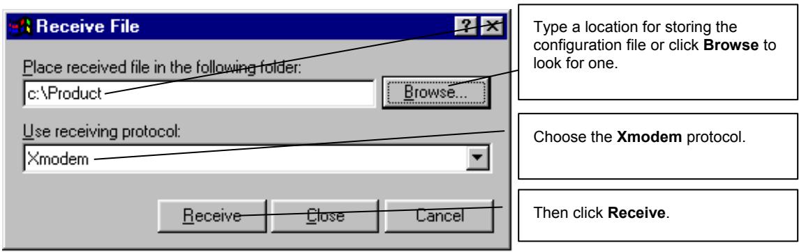
Figure 37-5 Backup Configuration Example
Step 4. After a successful backup you will see the following screen. Press any key to return to the SMT menu.
** Backup Configuration completed. OK.
<h3 id="hit-any-key-to-continue">Hit any key to continue.###</h3>
Figure 37-6 Successful Backup Confirmation Screen
37.3 Restore Configuration
This section shows you how to restore a previously saved configuration. Note that this function erases the current configuration before restoring a previous back up configuration; please do not attempt to restore unless you have a backup configuration file stored on disk.
FTP is the preferred method for restoring your current computer configuration to your Prestige since FTP is faster. Please note that you must wait for the system to automatically restart after the file transfer is complete.
WARNING! DO NOT INTERRUPT THE FILE TRANSFER PROCESS AS THIS MAY PERMANENTLY DAMAGE YOUR PRESTIGE.
37.3.1 Restore Using FTP
For details about backup using (T)FTP please refer to earlier sections on FTP and TFTP file upload in this chapter.
Menu 24.6 -- System Maintenance - Restore Configuration
To transfer the firmware and configuration file to your workstation, follow the procedure below:
- Launch the FTP client on your workstation.
- Type "open" and the IP address of your Prestige. Then type "root" and SMT password as requested.
- Type "put backupfilename rom-0" where backupfilename is the name of your backup configuration file on your workstation and rom-0 is the remote file name on the Prestige. This restores the configuration to your Prestige.
- The system reboots automatically after a successful file transfer
For details on FTP commands, please consult the documentation of your FTP client program. For details on backup using TFTP (note that you must remain in this menu to back up using TFTP), please see your Prestige manual.
Press ENTER to Exit:
Figure 37-7 Telnet into Menu 24.6
Step 1. Launch the FTP client on your computer.
Step 2. Enter “open”, followed by a space and the IP address of your Prestige.
Step 3. Press [ENTER] when prompted for a username.
Step 4. Enter your password as requested (the default is “1234”).
Step 5. Enter “bin” to set transfer mode to binary.
Step 6. Find the “rom” file (on your computer) that you want to restore to your Prestige.
Step 7. Use “put” to transfer files from the Prestige to the computer, for example, “put config.rom rom-0” transfers the configuration file “config.rom” on your computer to the Prestige. See earlier in this chapter for more information on filename conventions.
Step 8. Enter “quit” to exit the ftp prompt. The Prestige will automatically restart after a successful restore process.
37.3.2 Restore Using FTP Session Example
ftp> put config.rom rom-0
200 Port command okay
150 Opening data connection for STOR rom-0
226 File received OK
221 Goodbye for writing flash
ftp: 16384 bytes sent in 0.06Seconds 273.07Kbytes/sec.
ftp>quit
Figure 37-8 Restore Using FTP Session Example
Refer to section 37.2.5 to read about configurations that disallow TFTP and FTP over WAN.
37.3.3 Restore Via Console Port
Restore configuration via console port by following the HyperTerminal procedure shown next. Procedures using other serial communications programs should be similar.
Step 1. Display menu 24.6 and enter “y” at the following screen.
Ready to restore Configuration via Xmodem. Do you want to continue (y/n):
Figure 37-9 System Maintenance : Restore Configuration
Step 2. The following screen indicates that the Xmodem download has started.
Starting XMODEM download (CRC mode) ...
CCCCCC
Figure 37-10 System Maintenance : Starting Xmodem Download Screen
Step 3. Run the HyperTerminal program by clicking Transfer, then Send File as shown in the following screen.
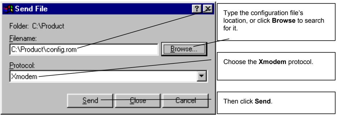
Figure 37-11 Restore Configuration Example
Step 4. After a successful restoration you will see the following screen. Press any key to restart the Prestige and return to the SMT menu.
Save to ROM
Hit any key to start system reboot.
Figure 37-12 Successful Restoration Confirmation Screen
37.4 Uploading Firmware and Configuration Files
This section shows you how to upload firmware and configuration files. You can upload configuration files by following the procedure in the previous Restore Configuration section or by following the instructions in Menu 24.7.2 – System Maintenance – Upload System Configuration File (for console port).
WARNING! DO NOT INTERRUPT THE FILE TRANSFER PROCESS AS THIS MAY PERMANENTLY DAMAGE YOUR PRESTIGE.
37.4.1 Firmware File Upload
FTP is the preferred method for uploading the firmware and configuration. To use this feature, your computer must have an FTP client.
When you telnet into the Prestige, you will see the following screens for uploading firmware and the configuration file using FTP.
Menu 24.7.1 - System Maintenance - Upload System Firmware
To upload the system firmware, follow the procedure below:
- Launch the FTP client on your workstation.
- Type "open" and the IP address of your system. Then type "root" and SMT password as requested.
- Type "put firmwarefilename ras" where "firmwarefilename" is the name of your firmware upgrade file on your workstation and "ras" is the remote file name on the system.
- The system reboots automatically after a successful firmware upload.
For details on FTP commands, please consult the documentation of your FTP client program. For details on uploading system firmware using TFTP (note that you must remain on this menu to upload system firmware using TFTP), please see your manual.
Press ENTER to Exit:
Figure 37-13 Telnet Into Menu 24.7.1 Upload System Firmware
37.4.2 Configuration File Upload
You see the following screen when you telnet into menu 24.7.2.
Menu 24.7.2 - System Maintenance - Upload System Configuration File
To upload the system configuration file, follow the procedure below:
- Launch the FTP client on your workstation.
- Type "open" and the IP address of your system. Then type "root" and SMT password as requested.
- Type "put configurationfilename rom-0" where "configurationfilename" is the name of your system configuration file on your workstation, which will be transferred to the "rom-0" file on the system.
- The system reboots automatically after the upload system configuration file process is complete.
For details on FTP commands, please consult the documentation of your FTP client program. For details on uploading system firmware using TFTP (note that you must remain on this menu to upload system firmware using TFTP), please see your manual.
Press ENTER to Exit:
Figure 37-14 Telnet Into Menu 24.7.2 System Maintenance
To upload the firmware and the configuration file, follow these examples
37.4.3 FTP File Upload Command from the DOS Prompt Example
Step 1. Launch the FTP client on your computer.
Step 2. Enter “open”, followed by a space and the IP address of your Prestige.
Step 3. Press [ENTER] when prompted for a username.
Step 4. Enter your password as requested (the default is “1234”).
Step 5. Enter “bin” to set transfer mode to binary.
Step 6. Use “put” to transfer files from the computer to the Prestige, for example, “put firmware.bin ras” transfers the firmware on your computer (firmware.bin) to the Prestige and renames it “ras”. Similarly, “put config.rom rom-0” transfers the configuration file on your computer (config.rom) to the Prestige and renames it “rom-0”. Likewise “get rom-0 config.rom” transfers the configuration file on the Prestige to your computer and renames it “config.rom.” See earlier in this chapter for more information on filename conventions.
Step 7. Enter "quit" to exit the ftp prompt.
The Prestige automatically restarts after a successful file upload.
37.4.4 FTP Session Example of Firmware File Upload
331 Enter PASS command
Password:
230 Logged in
ftp> bin
200 Type I OK
ftp> put firmware.bin ras
200 Port command okay
150 Opening data connection for STOR ras
226 File received OK
ftp: 1103936 bytes sent in 1.10Seconds 297.89Kbytes/sec.
ftp> quit
Figure 37-15 FTP Session Example of Firmware File Upload
More commands (found in GUI-based FTP clients) are listed earlier in this chapter.
Refer to section 37.2.5 to read about configurations that disallow TFTP and FTP over WAN.
37.4.5 TFTP File Upload
The Prestige also supports the uploading of firmware files using TFTP (Trivial File Transfer Protocol) over LAN. Although TFTP should work over WAN as well, it is not recommended.
To use TFTP, your computer must have both telnet and TFTP clients. To transfer the firmware and the configuration file, follow the procedure shown next.
Step 1. Use telnet from your computer to connect to the Prestige and log in. Because TFTP does not have any security checks, the Prestige records the IP address of the telnet client and accepts TFTP requests only from this address.
Step 2. Put the SMT in command interpreter (CI) mode by entering 8 in Menu 24 – System Maintenance.
Step 3. Enter the command “sys stdio 0” to disable the console timeout, so the TFTP transfer will not be interrupted. Enter “command sys stdio 5” to restore the five-minute console timeout (default) when the file transfer is complete.
Step 4. Launch the TFTP client on your computer and connect to the Prestige. Set the transfer mode to binary before starting data transfer.
Step 5. Use the TFTP client (see the example below) to transfer files between the Prestige and the computer. The file name for the firmware is “ras”.
Note that the telnet connection must be active and the Prestige in CI mode before and during the TFTP transfer. For details on TFTP commands (see following example), please consult the documentation of your TFTP client program. For UNIX, use “get” to transfer from the Prestige to the computer, “put” the other way around, and “binary” to set binary transfer mode.
37.4.6 TFTP Upload Command Example
The following is an example TFTP command:
tftp [-i] host put firmware.bin ras
where “i” specifies binary image transfer mode (use this mode when transferring binary files), “host” is the Prestige’s IP address and “put” transfers the file source on the computer (firmware.bin – name of the firmware on the computer) to the file destination on the remote host (ras - name of the firmware on the Prestige).
Commands that you may see in GUI-based TFTP clients are listed earlier in this chapter.
37.4.7 Uploading Via Console Port
FTP or TFTP are the preferred methods for uploading firmware to your Prestige. However, in the event of your network being down, uploading files is only possible with a direct connection to your Prestige via the console port. Uploading files via the console port under normal conditions is not recommended since FTP or TFTP is faster. Any serial communications program should work fine; however, you must use the Xmodem protocol to perform the download/upload.
37.4.8 Uploading Firmware File Via Console Port
Step 1. Select 1 from Menu 24.7 – System Maintenance – Upload Firmware to display Menu 24.7.1 – System Maintenance – Upload System Firmware, then follow the instructions as shown in the following screen.
Menu 24.7.1 - System Maintenance - Upload System Firmware
To upload system firmware:
1. Enter "y" at the prompt below to go into debug mode.
2. Enter "atur" after "Enter Debug Mode" message.
3. Wait for "Starting XMODEM upload" message before activating Xmodem upload on your terminal.
4. After successful firmware upload, enter "atgo" to restart the Prestige.
Warning: Proceeding with the upload will erase the current system firmware.
Do You Wish To Proceed: (Y/N)
Figure 37-16 Menu 24.7.1 as seen using the Console Port
Step 2. After the "Starting Xmodem upload" message appears, activate the Xmodem protocol on your computer. Follow the procedure as shown previously for the HyperTerminal program. The procedure for other serial communications programs should be similar.
37.4.9 Example Xmodem Firmware Upload Using HyperTerminal
Click Transfer, then Send File to display the following screen.
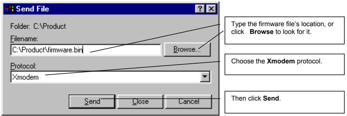
Figure 37-17 Example Xmodem Upload
After the configuration upload process has completed, restart the Prestige by entering “atgo”.
37.4.10 Uploading Configuration File Via Console Port
Step 1. Select 2 from Menu 24.7 – System Maintenance – Upload Firmware to display Menu 24.7.2 – System Maintenance – Upload System Configuration File. Follow the instructions as shown in the next screen.
Menu 24.7.2 - System Maintenance - Upload System Configuration File
To upload system configuration file:
1. Enter "y" at the prompt below to go into debug mode.
2. Enter "atlc" after "Enter Debug Mode" message.
3. Wait for "Starting XMODEM upload" message before activating Xmodem upload on your terminal.
4. After successful firmware upload, enter "atgo" to restart the system.
Warning:
1. Proceeding with the upload will erase the current configuration file.
2. The system's console port speed (Menu 24.2.2) may change when it is restarted; please adjust your terminal's speed accordingly. The password may change (menu 23), also.
3. When uploading the DEFAULT configuration file, the console port speed will be reset to 9600 bps and the password to "1234".
Do You Wish To Proceed: (Y/N)
Figure 37-18 Menu 24.7.2 as seen using the Console Port
Step 2. After the "Starting Xmodem upload" message appears, activate the Xmodem protocol on your computer. Follow the procedure as shown previously for the HyperTerminal program. The procedure for other serial communications programs should be similar.
Step 3. Enter “atgo” to restart the Prestige.
37.4.11 Example Xmodem Configuration Upload Using HyperTerminal
Click Transfer, then Send File to display the following screen.
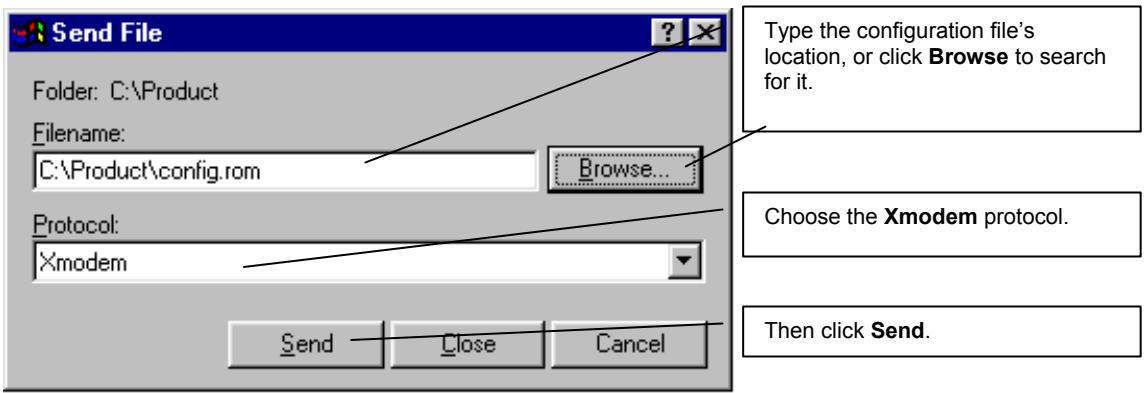
Figure 37-19 Example Xmodem Upload
After the configuration upload process has completed, restart the Prestige by entering “atgo”.
Chapter 38
System Maintenance
This chapter leads you through SMT menus 24.8 to 24.10.
38.1 Command Interpreter Mode
The Command Interpreter (CI) is a part of the main system firmware. The CI provides much of the same functionality as the SMT, while adding some low-level setup and diagnostic functions. Enter the CI from the SMT by selecting menu 24.8. See the included disk or the zyxel.com web site for more detailed information on CI commands. Enter 8 from Menu 24 — System Maintenance. A list of valid commands can be found by typing help or ? at the command prompt. Type “exit” to return to the SMT main menu when finished.
Menu 24 - System Maintenance
1. System Status
2. System Information
3. Log and Trace
4. Diagnostic
5. Backup Configuration
6. Restore Configuration
7. Firmware Update
8. Command Interpreter Mode
9. Call Control
10. Time and Date Setting
11. Remote Management
Enter Menu Selection Number:
Figure 38-1 Command Mode in Menu 24
| Copyright (c) 1994 - 2003 ZyXEL Communications Corp. | |||
| ras> ? | |||
| Valid commands are: | |||
| sys | exit | device | ether |
| wan | poe | config | ip |
| ppp | bridge | hdap | show |
| set | |||
| ras> | |||
Figure 38-2 Valid Commands
38.2 Call Control Support
Call Control Support is only applicable when Encapsulation is set to PPPoE in menu 4 or menu 11.1.
The budget management function allows you to set a limit on the total outgoing call time of the Prestige within certain times. When the total outgoing call time exceeds the limit, the current call will be dropped and any future outgoing calls will be blocked.
To access the call control menu, select option 9 in menu 24 to go to Menu 24.9 — System Maintenance — Call Control, as shown in the next table.
| Menu 24.9 - System Maintenance - Call Control |
| 1. Budget Management |
| Enter Menu Selection Number: |
Figure 38-3 Menu 24.9 System Maintenance : Call Control
38.2.1 Budget Management
Menu 24.9.1 shows the budget management statistics for outgoing calls. Enter 1 from Menu 24.9 — System Maintenance — Call Control to bring up the following menu.
| Menu 24.9.1 - System Maintenance - Budget Management | ||
| Remote Node | Connection Time/Total Budget | Elapsed Time/Total Period |
| 1.ChangeMe | No Budget | No Budget |
| 2.----- | --- | --- |
| 3.----- | --- | --- |
| 4.----- | --- | --- |
| 5.----- | --- | --- |
| 6.----- | --- | --- |
| 7.----- | --- | --- |
| 8.----- | --- | --- |
| Reset Node (0 to update screen): | ||
Figure 38-4 Menu 24.9.1 System Maintenance : Budget Management
The total budget is the time limit on the accumulated time for outgoing calls to a remote node. When this limit is reached, the call will be dropped and further outgoing calls to that remote node will be blocked. After each period, the total budget is reset. The default for the total budget is 0 minutes and the period is 0 hours, meaning no budget control. You can reset the accumulated connection time in this menu by entering the index of a remote node. Enter 0 to update the screen. The budget and the reset period can be configured in menu 11.1 for the remote node when PPPoE encapsulation is selected.
Table 38-1 Menu 24.9.1 System Maintenance : Budget Management
| FIELD | DESCRIPTION | EXAMPLE |
| Remote Node | Enter the index number of the remote node you want to reset (just one in this case) | 1 |
| Connection Time/Total Budget | This is the total connection time that has gone by (within the allocated budget that you set in menu 11.1. | 5/10 means that 5 minutes out of a total allocation of 10 minutes have lapsed. |
| Elapsed Time/Total Period | The period is the time cycle in hours that the allocation budget is reset (see menu 11.1.) The elapsed time is the time used up within this period. | 0.5/1 means that 30 minutes out of the 1 hour time period has lapsed. |
| Enter “0” to update the screen or press [ESC] to return to the previous screen. | ||
38.3 Time and Date Setting
The Prestige keeps track of the time and date. There is also a software mechanism to set the time manually or get the current time and date from an external server when you turn on your Prestige. Menu 24.10 allows you to update the time and date settings of your Prestige. The real time is then displayed in the Prestige error logs and firewall logs.
Select menu 24 in the main menu to open Menu 24 System Maintenance, as shown next.
Menu 24 - System Maintenance
1. System Status
2. System Information
3. Log and Trace
4. Diagnostic
5. Backup Configuration
6. Restore Configuration
7. Upload Firmware
8. Command Interpreter Mode
9. Call Control
10. Time and Date Setting
11. Remote Management
Enter Menu Selection Number:
Figure 38-5 Menu 24 System Maintenance
Then enter 10 to go to Menu 24.10 System Maintenance Time and Date Setting to update the time and date settings of your Prestige as shown in the following screen.
Menu 24.10 - System Maintenance - Time and Date Setting
Use Time Server when Bootup= None
Time Server Address= N/A
Current Time: 00 : 00 : 00
New Time (hh:mm:ss): 11 : 23 : 16
Current Date: 2000 - 01 - 01
New Date (yyyy-mm-dd): 2001 - 03 - 01
Time Zone= GMT
Daylight Saving= No
Start Date (mm-dd): 01 - 00
End Date (mm_dd): 01 - 00
Press ENTER to Confirm or ESC to Cancel:
Figure 38-6 Menu 24.10 System Maintenance: Time and Date Setting
Table 38-2 Menu 24.10 System Maintenance: Time and Date Setting
| FIELD | DESCRIPTION |
| Use Time Server when Bootup | Enter the time service protocol that your time server sends when you turn on the Prestige. Not all time servers support all protocols, so you may have to check with your ISP/network administrator or use trial and error to find a protocol that works. The main differences between them are the format.Daytime (RFC 867) format is day/month/year/time zone of the server.Time (RFC-868) format displays a 4-byte integer giving the total number of seconds since 1970/1/1 at 0:0:0.NTP (RFC-1305) is similar to Time (RFC-868).None. The default, enter the time manually. |
| Time Server Address | Enter the IP address or domain name of your time server. Check with your ISP/network administrator if you are unsure of this information. |
| Current Time New Time | This field displays an updated time only when you reenter this menu.Enter the new time in hour, minute and second format. |
| Current Date New Date | This field displays an updated date only when you re-enter this menu.Enter the new date in year, month and day format. |
| Time Zone | Press [SPACE BAR] and then [ENTER] to set the time difference between your time zone and Greenwich Mean Time (GMT). |
| Daylight Saving Start Date End Date | If you use daylight savings time, then choose Yes.If using daylight savings time, enter the month and day that it starts on.If using daylight savings time, enter the month and day that it ends on |
| Once you have filled in this menu, press [ENTER] at the message “Press ENTER to Confirm or ESC to Cancel” to save your configuration, or press [ESC] to cancel. | |
38.3.1 Resetting the Time
The Prestige resets the time in three instances:
i. On leaving menu 24.10 after making changes.
ii. When the Prestige starts up, if there is a time server configured in menu 24.10.
iii. 24-hour intervals after starting.
Chapter 39
Remote Management
This chapter covers remote management (SMT menu 24.11).
39.1 Remote Management Overview
Remote management allows you to determine which services/protocols can access which Prestige interface (if any) from which computers.
When you configure remote management to allow management from the WAN, you still need to configure a firewall rule to allow access. See the firewall chapters for details on configuring firewall rules.
39.2 Remote Management
To disable remote management of a service, select Disable in the corresponding Server Access field.
Enter 11 from menu 24 to display Menu 24.11 — Remote Management Control.
39.2.1 Remote Management Setup
You may manage your Prestige from a remote location via:
the Internet (WAN only), the LAN only, All (LAN and WAN) or Disable (neither).
WAN only (Internet)
ALL (LAN and WAN)
LAN only
▶ Disable (Neither)
If you enable remote management of a service, but have applied a filter to block the service, then you will not be able to remotely manage the service.
Enter 11, from menu 24, to display Menu 24.11 — Remote Management Control (shown next).
Menu 24.11 - Remote Management Control
TELNET Server:
Server Port = 23 Server Access = LAN only
Secured Client IP = 0.0.0.0
FTP Server:
Server Port = 21 Server Access = LAN only
Secured Client IP = 0.0.0.0
Web Server:
Server Port = 80 Server Access = LAN only
Secured Client IP = 0.0.0.0
Press ENTER to Confirm or ESC to Cancel:
Figure 39-1 Menu 24.11 Remote Management Control
The following table describes the fields in this menu.
Table 39-1 Menu 24.11 Remote Management Control
| FIELD | DESCRIPTION | EXAMPLE |
| Telnet ServerFTP ServerWeb Server | Each of these read-only labels denotes a service that you may use to remotely manage the Prestige. | |
| Port | This field shows the port number for the remote management service. You may change the port number for a service if needed, but you must use the same port number to use that service for remote management. | 23 |
| Access | Select the access interface (if any) by pressing the [SPACE BAR]. Choices are: LAN only, WAN only, All or Disable. The default is LAN only. | LAN only |
| Secured Client IP | The default 0.0.0.0 allows any client to use this service to remotely manage the Prestige. Enter an IP address to restrict access to a client with a matching IP address. | 0.0.0.0 |
| Once you have filled in this menu, press [ENTER] at the message "Press ENTER to Confirm or ESC to Cancel" to save your configuration, or press [ESC] to cancel. | ||
39.2.2 Remote Management Limitations
Remote management over LAN or WAN will not work when:
- A filter in menu 3.1 (LAN) or in menu 11.5 (WAN) is applied to block a Telnet, FTP or Web service.
- You have disabled that service in menu 24.11.
- The IP address in the Secured Client IP field (menu 24.11) does not match the client IP address. If it does not match, the Prestige will disconnect the session immediately.
- There is already another remote management session of the same type (Telnet, FTP or Web) running. You may only have one remote management session of the same type running at one time.
- There is a web remote management session running with a Telnet session. A Telnet session will be disconnected if you begin a web session; it will not begin if there already is a web session.
39.3 Remote Management and NAT
When NAT is enabled:
Use the Prestige's WAN IP address when configuring from the WAN.
Use the Prestige's LAN IP address when configuring from the LAN.
39.4 System Timeout
There is a system timeout of five minutes (300 seconds) for Telnet/web/FTP connections. Your Prestige will automatically log you out if you do nothing in this timeout period, except when it is continuously updating the status in menu 24.1 or when sys stdio has been changed on the command line.
Chapter 40
IP Policy Routing
This chapter covers setting and applying policies used for IP routing.
40.1 IP Policy Routing Overview
Traditionally, routing is based on the destination address only and the IAD takes the shortest path to forward a packet. IP Routing Policy (IPPR) provides a mechanism to override the default routing behavior and alter the packet forwarding based on the policy defined by the network administrator. Policy-based routing is applied to incoming packets on a per interface basis, prior to the normal routing.
40.2 Benefits of IP Policy Routing
- Source-Based Routing – Network administrators can use policy-based routing to direct traffic from different users through different connections.
- Quality of Service (QoS) – Organizations can differentiate traffic by setting the precedence or TOS (Type of Service) values in the IP header at the periphery of the network to enable the backbone to prioritize traffic.
- Cost Savings – IPPR allows organizations to distribute interactive traffic on high-bandwidth, high-cost paths while using low-cost paths for batch traffic.
- Load Sharing – Network administrators can use IPPR to distribute traffic among multiple paths.
40.3 Routing Policy
Individual routing policies are used as part of the overall IPPR process. A policy defines the matching criteria and the action to take when a packet meets the criteria. The action is taken only when all the criteria are met. The criteria includes the source address and port, IP protocol (ICMP, UDP, TCP, etc.), destination address and port, TOS and precedence (fields in the IP header) and length. The inclusion of length criterion is to differentiate between interactive and bulk traffic. Interactive applications, for example, telnet, tend to have short packets, while bulk traffic, for example, file transfer, tends to have large packets.
The actions that can be taken include:
- routing the packet to a different gateway (and hence the outgoing interface).
- setting the TOS and precedence fields in the IP header.
IPPR follows the existing packet filtering facility of RAS in style and in implementation. The policies are divided into sets, where related policies are grouped together. A user defines the policies before applying them to an interface or a remote node, in the same fashion as the filters. There are 12 policy sets with six policies in each set.
40.4 IP Routing Policy Setup
Menu 25 shows all the policies defined.
| Menu 25 - IP Routing Policy Setup | |||
| Policy Set # | Name | Policy Set # | Name |
| 1 | test | 7 | _ |
| 2 | _ | 8 | _ |
| 3 | _ | 9 | _ |
| 4 | _ | 10 | _ |
| 5 | _ | 11 | _ |
| 6 | _ | 12 | _ |
| Enter Policy Set Number to Configure= 0 | |||
| Edit Name= N/A | |||
| Press ENTER to Confirm or ESC to Cancel: | |||
Figure 40-1 Menu 25 IP Routing Policy Setup
To setup a routing policy, perform the following procedures:
Step 1. Type 25 in the main menu to open Menu 25 – IP Routing Policy Setup.
Step 2. Type the index of the policy set you want to configure to open Menu 25.1 – IP Routing Policy Setup.
Menu 25.1 shows the summary of a policy set, including the criteria and the action of a single policy, and whether a policy is active or not. Each policy contains two lines. The former part is the criteria of the incoming packet and the latter is the action. Between these two parts, separator “|” means the action is taken on criteria matched and separator “=” means the action is taken on criteria not matched.
| Menu 25.1 - IP Routing Policy Setup | |
| # A | Criteria/Action |
| - - | |
| 1 Y | SA=1.1.1.1-1.1.1.1,DA=2.2.2.2-2.2.2.5 SP=20-25,DP=20-25,P=6,T=NM,PR=0 |GW=192.168.1.1,T=MT,PR=0 |
| 2 N | |
| 3 N | |
| 4 N | |
| 5 N | |
| 6 N | |
| Enter Policy Rule Number (1-6) to Configure: | |
Figure 40-2 Menu 25.1 IP Routing Policy Setup
Table 40-1 Menu 25.1 IP Routing Policy Setup
| ABBREVIATION | MEANING | |
| Criterion | SA | Source IP Address |
| SP | Source Port | |
| DA | Destination IP Address | |
| DP | Destination Port | |
| P | IP layer 4 protocol number (TCP=6, UDP=17...) | |
| T | Type of service of incoming packet | |
| PR | Precedence of incoming packet | |
| Action | GW | Gateway IP address |
| T | Outgoing Type of service | |
| P | Outgoing Precedence | |
| Service | NM | Normal |
| MD | Minimum Delay | |
| MT | Maximum Throughput | |
| MR | Maximum Reliability | |
| MC | Minimum Cost | |
Type a number from 1 to 6 to display Menu 25.1.1 – IP Routing Policy (see the next figure). This menu allows you to configure a policy rule.
Menu 25.1.1 - IP Routing Policy
Policy Set Name= test
Active= Yes
Criteria:
    IP Protocol = 6
    Type of Service= Normal Packet length= 40
    Precedence = 0 Len Comp= N/A
    Source:
    addr start= 1.1.1.1 end= 1.1.1.1
    port start= 20 end= 20
    Destination:
    addr start= 2.2.2.2 end= 2.2.2.2
    port start= 20 end= 20
Action= Matched
Gateway addr = 192.168.1.1 Log= No
Type of Service= Max Thruput
Precedence = 0
Press ENTER to Confirm or ESC to Cancel:
Press Space Bar to Toggle.
Figure 40-3 Menu 25.1.1 IP Routing Policy
The following table describes the fields in this menu.
Table 40-2 Menu 25.1.1 IP Routing Policy
| FIELD | DESCRIPTION |
| Policy Set Name | This is the policy set name assigned in Menu 25 – IP Routing Policy Setup. |
| Active | Press [SPACE BAR] and then [ENTER] to select Yes to activate or No to deactivate the policy. Inactive policies are displayed with a minus sign “-” in SMT menu 25. |
| Criteria | |
| IP Protocol | IP layer 4 protocol, for example, UDP, TCP, ICMP, etc. |
| Type of Service | Prioritize incoming network traffic by choosing from Don’t Care, Normal, Min Delay, Max Thruput, Min Cost or Max Reliable. |
| Precedence | Precedence value of the incoming packet. Press [SPACE BAR] and then [ENTER] to select a value from 0 to 7 or Don’t Care. |
| Packet Length | Type the length of incoming packets (in bytes). The operators in the Len Comp (next field) apply to packets of this length. |
Table 40-2 Menu 25.1.1 IP Routing Policy
| FIELD | DESCRIPTION |
| Len Comp | Press [SPACE BAR] and then [ENTER] to choose from Equal, Not Equal, Less, Greater, Less or Equal or Greater or Equal. |
| Source: | |
| addr start / end | Source IP address range from start to end. |
| port start / end | Source port number range from start to end; applicable only for TCP/UDP. |
| Destination: | |
| addr start / end | Destination IP address range from start to end. |
| port start / end | Destination port number range from start to end; applicable only for TCP/UDP. |
| Action | Specifies whether action should be taken on criteria Matched or Not Matched. |
| Gateway addr | Defines the outgoing gateway address. The gateway must be on the same subnet as the Prestige if it is on the LAN, otherwise, the gateway must be the IP address of a remote node. The default gateway is specified as 0.0.0.0. |
| Type of Service | Set the new TOS value of the outgoing packet. Prioritize incoming network traffic by choosing No Change, Normal, Min Delay, Max Thruput, Max Reliable or Min Cost. |
| Precedence | Set the new outgoing packet precedence value. Values are 0 to 7 or No Change. |
| Log | Press [SPACE BAR] and then [ENTER] to select Yes to make an entry in the system log when a policy is executed. |
| When you have completed this menu, press [ENTER] at the prompt “Press ENTER to confirm or ESC to cancel” to save your configuration or press [ESC] to cancel and go back to the previous screen. | |
40.5 Applying an IP Policy
This section shows you where to apply the IP policies after you design them.
40.5.1 Ethernet IP Policies
From Menu 3 — Ethernet Setup, type 2 to go to Menu 3.2 — TCP/IP and DHCP Ethernet Setup.
You can choose up to four IP policy sets (from 12) by typing their numbers separated by commas, for example, 2, 4, 7, 9.
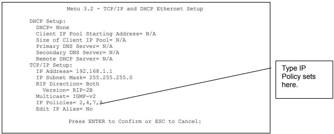
Figure 40-4 Menu 3.2 TCP/IP and DHCP Ethernet Setup
Go to menu 11.3 (shown next) and type the number(s) of the IP Routing Policy set(s) as appropriate. You can cascade up to four policy sets by typing their numbers separated by commas.
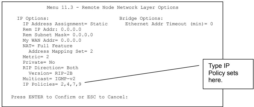
Figure 40-5 Menu 11.3 Remote Node Network Layer Options
40.6 IP Policy Routing Example
If a network has both Internet and remote node connections, you can route Web packets to the Internet using one policy and route FTP packets to a remote network using another policy. See the next figure.
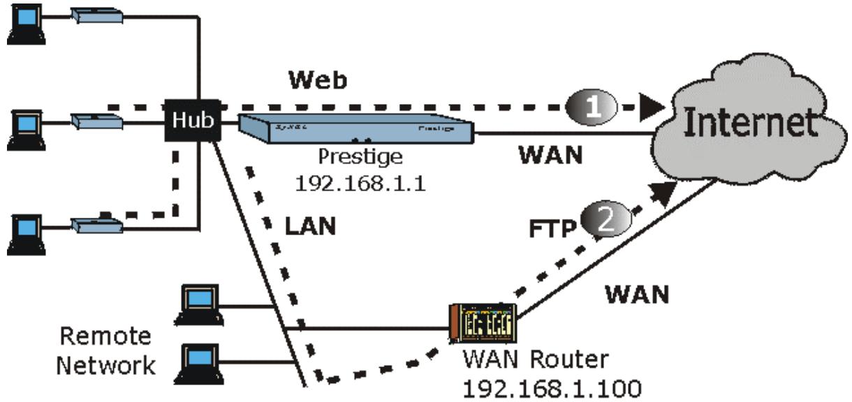
flowchart
graph TD
    A["Computer"] --> B["Hub"]
    C["Computer"] --> B
    D["Computer"] --> B
    B --> E["Web"]
    E --> F["Prestige 192.168.1.1"]
    F --> G["WAN"]
    G --> H["Internet"]
    I["Remote Network"] --> J["WAN Router 192.168.1.100"]
    J --> K["FTP 2"]
    K --> H
    L["LAN"] -.-> E
    M["WiN"] -.-> J

Figure 40-6 Example of IP Policy Routing
To force Web packets coming from clients with IP addresses of 192.168.1.33 to 192.168.1.64 to be routed to the Internet via the WAN port of the Prestige, follow the steps as shown next.
Step 1. Create a routing policy set in menu 25.
Step 2. Create a rule for this set in Menu 25.1.1 — IP Routing Policy as shown next.
Menu 25.1.1 - IP Routing Policy
Policy Set Name= set1
Active= Yes
Criteria:
    IP Protocol = 6
    Type of Service= Don't Care Packet length= 10
    Precedence = Don't Care Len Comp= N/A
    Source:
    addr start= 192.168.1.2 end= 192.168.1.64
    port start= 0 end= N/A
Destination:
    addr start= 0.0.0.0 end= N/A
    port start= 80 end= 80
Action= Matched
Gateway addr = 192.168.1.1 Log= No
Type of Service= No Change
Precedence = No Change
Press ENTER to Confirm or ESC to Cancel:
Press Space Bar to Toggle.
Figure 40-7 IP Routing Policy Example
Step 3. Check Menu 25.1 — IP Routing Policy Setup to see if the rule is added correctly.
Step 4. Create another policy set in menu 25.
Step 5. Create a rule in menu 25.1 for this set to route packets from any host (IP=0.0.0.0 means any host) with protocol TCP and port FTP access through another gateway (192.168.1.100).
Menu 25.1.1 - IP Routing Policy
Policy Set Name= set2
Active= Yes
Criteria:
    IP Protocol = 6
    Type of Service= Don't Care Packet length= 10
    Precedence = Don't Care Len Comp= N/A
    Source:
    addr start= 0.0.0.0 end= N/A
    port start= 0 end= N/A
    Destination:
    addr start= 0.0.0.0 end= N/A
    port start= 20 end= 21
Action= Matched
Gateway addr =192.168.1.100 Log= No
Type of Service= No Change
Precedence = No Change
Press ENTER to Confirm or ESC to Cancel:
Press Space Bar to Toggle.
Figure 40-8 IP Routing Policy Example
Step 6. Check Menu 25.1 — IP Routing Policy Setup to see if the rule is added correctly.
Step 7. Apply both policy sets in menu 3.2 as shown next.
Menu 3.2 - TCP/IP and DHCP Ethernet Setup

DHCP Setup
    DHCP= Server
    Client IP Pool Starting Address= 192.168.1.33
    Size of Client IP Pool= 64
    Primary DNS Server= 0.0.0.0
    Secondary DNS Server= 0.0.0.0
    Remote DHCP Server= N/A
TCP/IP Setup:
    IP Address= 192.168.1.1
    IP Subnet Mask= 255.255.255.0
    RIP Direction= Both
    Version= RIP-1
    Multicast= None
    IP Policies= 1,2
Edit IP Alias= No

Press ENTER to Confirm or ESC to Cancel:

Press Space Bar to Toqgle.
Figure 40-9 Applying IP Policies Example
Chapter 41
Call Scheduling
Call scheduling (applicable for PPPoA or PPPoE encapsulation only) allows you to dictate when a remote node should be called and for how long.
41.1 Introduction
The call scheduling feature allows the Prestige to manage a remote node and dictate when a remote node should be called and for how long. This feature is similar to the scheduler in a video cassette recorder (you can specify a time period for the VCR to record). You can apply up to 4 schedule sets in Menu 11.1 — Remote Node Profile. From the main menu, enter 26 to access Menu 26 — Schedule Setup as shown next.
Menu 26 - Schedule Setup
Schedule
Set #
Name
Schedule
Set #
Name
1
2
3
4
5
6

7
8
9
10
11
12
Enter Schedule Set Number to Configure=
Edit Name=
Press ENTER to Confirm or ESC to Cancel:
Figure 41-1 Menu 26 Schedule Setup
Lower numbered sets take precedence over higher numbered sets thereby avoiding scheduling conflicts. For example, if sets 1, 2, 3 and 4 in are applied in the remote node then set 1 will take precedence over set 2, 3 and 4 as the Prestige, by default, applies the lowest numbered set first. Set 2 will take precedence over set 3 and 4, and so on.
You can design up to 12 schedule sets but you can only apply up to four schedule sets for a remote node.
To delete a schedule set, enter the set number and press [SPACE BAR] and then [ENTER] (or delete) in the Edit Name field.
To setup a schedule set, select the schedule set you want to setup from menu 26 (1-12) and press [ENTER] to see Menu 26.1 — Schedule Set Setup as shown next.
Menu 26.1 - Schedule Set Setup
Active= Yes
Start Date(yyyy/mm/dd) = 2000 - 01 - 01
How Often= Once
Once:
Date(yyyy/mm/dd) = 2000 - 01 - 01
Weekdays:
Sunday= N/A
Monday= N/A
Tuesday= N/A
Wednesday= N/A
Thursday= N/A
Friday= N/A
Saturday= N/A
Start Time (hh:mm)= 00 : 00
Duration (hh:mm)= 00 : 00
Action= Forced On
Press ENTER to Confirm or ESC to Cancel:
Press Space Bar to Toggle
Figure 41-2 Menu 26.1 Schedule Set Setup
If a connection has been already established, your Prestige will not drop it. Once the connection is dropped manually or it times out, then that remote node can't be triggered up until the end of the Duration.
Table 41-1 Menu 26.1 Schedule Set Setup
| FIELD | DESCRIPTION | EXAMPLE |
| Active | Press [SPACE BAR] to select Yes or No. Choose Yes and press [ENTER] to activate the schedule set. | Yes |
| Start Date | Enter the start date when you wish the set to take effect in year -month-date format. Valid dates are from the present to 2036-February-5. | 2000-01-01 |
Table 41-1 Menu 26.1 Schedule Set Setup
| FIELD | DESCRIPTION | EXAMPLE |
| How Often | Should this schedule set recur weekly or be used just once only? Press the [SPACE BAR] and then [ENTER] to selectOnce or Weekly. Both these options are mutually exclusive.If Once is selected, then all weekday settings are N/A.When Once is selected, the schedule rule deletes automatically after the scheduled time elapses. | Once |
| Once:Date | If you selected Once in the How Often field above, then enter the date the set should activate here in year-month-date format. | 2000-01-01 |
| Weekday :Day | If you selected Weekly in the How Often field above, then select the day(s) when the set should activate (and recur) by going to that day(s) and pressing [SPACE BAR] to selectYes, then press [ENTER]. | YesNoN/A |
| Start Time | Enter the start time when you wish the schedule set to take effect in hour-minute format. | 09:00 |
| Duration | Enter the maximum length of time this connection is allowed in hour-minute format. | 08:00 |
| Action | Forced On means that the connection is maintained whether or not there is a demand call on the line and will persist for the time period specified in the Duration field.Forced Down means that the connection is blocked whether or not there is a demand call on the line.Enable Dial-On-Demand means that this schedule permits a demand call on the line. Disable Dial-On-Demand means that this schedule prevents a demand call on the line. | Forced On |
| When you have completed this menu, press [ENTER] at the prompt “Press ENTER to confirm or ESC to cancel” to save your configuration or press [ESC] to cancel and go back to the previous screen. | ||
Once your schedule sets are configured, you must then apply them to the desired remote node(s). Enter 11 from the Main Menu and then enter the target remote node index. Using [SPACE BAR], select PPPoE or PPPoA in the Encapsulation field and then press [ENTER] to make the schedule sets field available as shown next.
Menu 11.1 - Remote Node Profile
Rem Node Name= ChangeMe
Active= Yes
Route= IP
Bridge= No
Encapsulation= PPPoE
Multiplexing=VC-based
Service Name=
Incoming
    Rem Login=
    Rem Password= *****
Outgoing=
    My Login=?
    My Password= *****
Authen= CHAP/PAP
Edit IP/Bridge= No
Edit ATM Options= No
Telco Option:
Allocated Budget(min)= 0
Period(hr)= 0
Schedules= 1,2,3,4
Nailed-Up Connection= No
Session Options:
Edit Filter Sets= No
Idle Timeout(sec)= 100
Apply your schedule sets here.
Press ENTER to Confirm or ESC to Cancel:
Press Space Bar to Toggle.
Figure 41-3 Applying Schedule Set(s) to a Remote Node (PPPoE)
You can apply up to four schedule sets, separated by commas, for one remote node. Change the schedule set numbers to your preference(s).
Part X:
SMT VPN/IPSec and Internal SPTGEN
This part provides information about configuring VPN/IPSec for secure communications and Internal SPTGEN for configuration of multiple Prestiges.
See the web configurator parts of this guide for background information on features configurable by web configurator and SMT.
Chapter 42
VPN/IPSec Setup
This chapter introduces the VPN SMT menus.
42.1 VPN/IPSec Overview
The VPN/IPSec main SMT menu has these main submenus:
- Define VPN policies in menu 27.1 submenus, including security policies, endpoint IP addresses, peer IPSec router IP address and key management.
- Menu 27.2 - SA Monitor allows you to manage (refresh or disconnect) your SA connections.
This is an overview of the VPN menu tree.
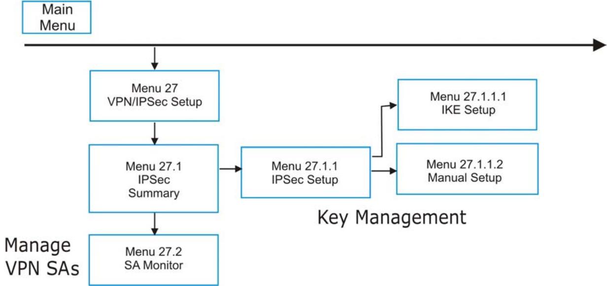
flowchart
graph TD
    A["Main Menu"] --> B["Menu 27 VPN/IPSec Setup"]
    B --> C["Menu 27.1 IPSec Summary"]
    C --> D["Menu 27.2 SA Monitor"]
    E["Menu 27.1.1 IKE Setup"] --> F["Menu 27.1.1 IPSec Setup"]
    G["Menu 27.1.1.2 Manual Setup"] --> F
    F --> H["Key Management"]
    D --> H
Figure 42-1 VPN SMT Menu Tree
From the main menu, enter 27 to display the first VPN menu (shown next).
Menu 27 - VPN/IPSec Setup
1. IPSec Summary
2. SA Monitor
Enter Menu Selection Number:
Figure 42-2 Menu 27 VPN/IPSec Setup
42.2 IPSec Summary Screen
Type 1 in menu 27 and then press [ENTER] to display Menu 27.1 IPSec Summary. This is a summary read-only menu of your IPSec rules (tunnels). Edit or create an IPSec rule by selecting an index number and then configuring the associated submenus.
Menu 27.1 - IPSec Summary
<h1 id="name-a-local-addr-start-local-addr-end-encap-ipsec-algorithm">Name A Local Addr Start - Local Addr End Encap IPSec Algorithm</h1>
Key Mgt Remote Addr Start - Remote Addr End Secure GW Addr
- ---- - ---- ---- ---- ----
1 Taiwan Y 192.168.1.35 192.168.1.38 Tunnel ESP DES MD5
IKE 172.16.2.40 172.16.2.46 193.81.13.2
2 zw50 N 1.1.1.1 1.1.1.1 Tunnel AH SHA1
IKE 4.4.4.4 255.255.0.0 zw50test.zyxel.
3 China N 192.168.1.40 192.168.1.42 Tunnel ESP DES MD5
IKE N/A N/A 0.0.0.0
4
5
Select Command= None Select Rule= N/A
Press ENTER to Confirm or ESC to Cancel:
Figure 42-3 Menu 27.1 IPSec Summary
Table 42-1 Menu 27.1 IPSec Summary
| FIELD | DESCRIPTION | EXAMPLE |
| # | This is the VPN policy index number. | 1 |
| Name | This field displays the unique identification name for this VPN rule. The name may be up to 32 characters long but only 10 characters will be displayed here. | Taiwan |
| A | Y signifies that this VPN rule is active. | Y |
| Local Addr Start | When the Addr Type field in Menu 27.1.1 IPSec Setup is configured to Single, this is a static IP address on the LAN behind your Prestige.When the Addr Type field in Menu 27.1.1 IPSec Setup is configured to Range, this is the beginning (static) IP address, in a range of computers on the LAN behind your Prestige.When the Addr Type field in Menu 27.1.1 IPSec Setup is configured to SUBNET, this is a static IP address on the LAN behind your Prestige. | 192.168.1.35 |
| Local Addr End | When the Addr Type field in Menu 27.1.1 IPSec Setup is configured to Single, this is the same (static) IP address as in the Local Addr Start field.When the Addr Type field in Menu 27.1.1 IPSec Setup is configured to Range, this is the end (static) IP address, in a range of computers on the LAN behind your Prestige.When the Addr Type field in Menu 27.1.1 IPSec Setup is configured to SUBNET, this is a subnet mask on the LAN behind your Prestige. | 192.168.1.38 |
| Encap | This field displays Tunnel mode or Transport mode. See earlier for a discussion of these. You need to finish configuring the VPN policy in menu 27.1.1.1 or 27.1.1.2 if ??? is displayed. | Tunnel |
Table 42-1 Menu 27.1 IPSec Summary
| FIELD | DESCRIPTION | EXAMPLE |
| IPSec Algorithm | This field displays the security protocols used for an SA. ESP provides confidentiality and integrity of data by encrypting the data and encapsulating it into IP packets. Encryption methods include 56-bit DES and 168-bit 3DES. NULL denotes a tunnel without encryption.AH (Authentication Header) provides strong integrity and authentication by adding authentication information to IP packets. This authentication information is calculated using header and payload data in the IP packet. This provides an additional level of security. AH choices are MD5 (default - 128 bits) and SHA -1(160 bits).Both AH and ESP increase the Prestige's processing requirements and communications latency (delay).You need to finish configuring the VPN policy in menu 27.1.1.1 or 27.1.1.2 if ??? is displayed. | ESP DES MD5 |
| Key Mgt | This field displays the SA's type of key management, (IKE or Manual). | IKE |
| Remote Addr Start | When the Addr Type field in Menu 27.1.1 IPSec Setup is configured to Single, this is a static IP address on the network behind the remote IPSec router.When the Addr Type field in Menu 27.1.1 IPSec Setup is configured to Range, this is the beginning (static) IP address, in a range of computers on the network behind the remote IPSec router.When the Addr Type field in Menu 27.1.1 IPSec Setup is configured to SUBNET, this is a static IP address on the network behind the remote IPSec router.This field displays N/A when you configure the Secure Gateway Addr field in SMT 27.1.1 to 0.0.0.0. | 172.16.2.40 |
Table 42-1 Menu 27.1 IPSec Summary
| FIELD | DESCRIPTION | EXAMPLE |
| Remote Addr End | When the Addr Type field in Menu 27.1.1 IPSec Setup is configured to Single, this is the same (static) IP address as in the Remote Addr Start field.When the Addr Type field in Menu 27.1.1 IPSec Setup is configured to Range, this is the end (static) IP address, in a range of computers on the network behind the remote IPSec router.When the Addr Type field in Menu 27.1.1 IPSec Setup is configured to SUBNET, this is a subnet mask on the network behind the remote IPSec router.This field displays N/A when you configure the Secure Gateway Addr field in SMT 27.1.1 to 0.0.0.0. | 172.16.2.46 |
| Secure GW Addr | This is the WAN IP address or the domain name (up to the first 15 characters are displayed) of the IPSec router with which you are making the VPN connection. This field displays 0.0.0.0 when you configure the Secure Gateway Addr field in SMT 27.1.1 to 0.0.0.0. | 193.81.13.2 |
| Select Command | Press [SPACE BAR] to choose from None, Edit, Delete, Go To Rule, Next Page or Previous Page and then press [ENTER]. You must select a rule in the next field when you choose the Edit, Delete or Go To commands.Select None and then press [ENTER] to go to the “Press ENTER to Confirm...” prompt.Use Edit to create or edit a rule. Use Delete to remove a rule. To edit or delete a rule, first make sure you are on the correct page. When a VPN rule is deleted, subsequent rules do not move up in the page list.Use Go To Rule to view the page where your desired rule is listed.Select Next Page or Previous Page to view the next or previous page of rules (respectively). | None |
| Select Rule | Type the VPN rule index number you wish to edit or delete and then press [ENTER]. | 3 |
| When you have completed this menu, press [ENTER] at the prompt “Press ENTER to Confirm...” to save your configuration, or press [ESC] at any time to cancel. | ||
42.3 IPSec Setup
Select Edit in the Select Command field; type the index number of a rule in the Select Rule field and press [ENTER] to edit the VPN using the menu shown next.
You must also configure menu 27.1.1.1 or menu 27.1.1.2 to fully configure and use a VPN.
Menu 27.1.1 - IPSec Setup
Index= 1    Name= Taiwan
Active= Yes    Keep Alive= No
Local ID type    Content:
My IP Addr= 0.0.0.0
Peer ID type    Content:
Secure Gateway Address= zw50test.zyxel.com.tw
Protocol= 0
Local:    Addr Type= SINGLE
    IP Addr Start= 1.1.1.1    End/Subnet Mask= N/A
    Port Start= 0    End= N/A
Remote:    Addr Type= SUBNET
    IP Addr Start= 4.4.4.4    End/Subnet Mask= 255.255.0.0
    Port Start= 0    End= N/A
Enable Replay Detection = No
Key Management= IKE
Edit Key Management Setup= No

Press ENTER to Confirm or ESC to Cancel:
Figure 42-4 Menu 27.1.1 IPSec Setup
The following table describes the fields in this menu.
Table 42-2 Menu 27.1.1 IPSec Setup
| FIELD | DESCRIPTION | EXAMPLE |
| Index | This is the VPN rule index number you selected in the previous menu. | 1 |
| Name | Enter a unique identification name for this VPN rule. The name may be up to 32 characters long but only 10 characters will be displayed inMenu27.1 - IPSec Summary. | Taiwan |
| Active | Press [SPACE BAR] to choose eitherYesor No.Choose Yesand press [ENTER] to activate the VPN tunnel. This field determines whether a VPN rule is applied before a packet leaves the firewall. | Yes |
Table 42-2 Menu 27.1.1 IPSec Setup
| FIELD | DESCRIPTION | EXAMPLE |
| Keep Alive | Press [SPACE BAR] to choose either Yes or No. Choose Yes and press [ENTER] to have the Prestige automatically re-initiate the SA after the SA lifetime times out, even if there is no traffic. The remote IPSec router must also have keep alive enabled in order for this feature to work. | No |
| Local ID type | Press [SPACE BAR] to choose IP, DNS, or E-mail and press [ENTER].Select IP to identify this Prestige by its IP address.Select DNS to identify this Prestige by a domain name.Select E-mail to identify this Prestige by an e-mail address. | |
| Content | When you select IP in the Local ID Type field, type the IP address of your computer or leave the field blank to have the Prestige automatically use its own IP address.When you select DNS in the Local ID Type field, type a domain name (up to 31 characters) by which to identify this Prestige.When you select E-mail in the Local ID Type field, type an e-mail address (up to 31 characters) by which to identify this Prestige.The domain name or e-mail address that you use in the Content field is used for identification purposes only and does not need to be a real domain name or e-mail address. | |
| My IP Addr | Enter the IP address of your Prestige. The Prestige uses its current WAN IP address (static or dynamic) in setting up the VPN tunnel if you leave this field as 0.0.0.0.The VPN tunnel has to be rebuilt if this IP address changes. | 0.0.0.0 |
| Peer ID type | Press [SPACE BAR] to choose IP, DNS, or E-mail and press [ENTER].Select IP to identify the remote IPSec router by its IP address.Select DNS to identify the remote IPSec router by a domain name.Select E-mail to identify the remote IPSec router by an e-mail address. |
Table 42-2 Menu 27.1.1 IPSec Setup
| FIELD | DESCRIPTION | EXAMPLE |
| Content | When you select IP in the Peer ID Type field, type the IP address of the computer with which you will make the VPN connection or leave the field blank to have the Prestige automatically use the address in the Secure Gateway Address field.When you select DNS in the Peer ID Type field, type a domain name (up to 31 characters) by which to identify the remote IPSec router.When you select E-mail in the Peer ID Type field, type an e-mail address (up to 31 characters) by which to identify the remote IPSec router.The domain name or e-mail address that you use in the Content field is used for identification purposes only and does not need to be a real domain name or e-mail address. The domain name also does not have to match the remote router's IP address or what you configure in the Secure Gateway Address field below. | |
| Secure Gateway Address | Type the IP address or the domain name (up to 31 characters) of the IPSec router with which you're making the VPN connection.Set this field to 0.0.0.0 if the remote IPSec router has a dynamic WAN IP address (the Key Management field must be set to IKE, see later). | Zw50test.com.tw |
| Protocol | Enter 1 for ICMP, 6 for TCP, 17 for UDP, etc. 0 is the default and signifies any protocol. | 0 |
| Local | Local IP addresses must be static and correspond to the remote IPSec router's configured remote IP addresses.Two active SAs cannot have the local and remote IP address(es) both the same. Two active SAs can have the same local or remote IP address, but not both. You can configure multiple SAs between the same local and remote IP addresses, as long as only one is active at any time. | |
| Addr Type | Press [SPACE BAR] to choose SINGLE, RANGE, or SUBNET and press [ENTER]. Select SINGLE with a single IP address. Select RANGE for a specific range of IP addresses. Select SUBNET to specify IP addresses on a network by their subnet mask. | SINGLE |
Table 42-2 Menu 27.1.1 IPSec Setup
| FIELD | DESCRIPTION | EXAMPLE |
| IP Addr Start | When the Addr Type field is configured to Single, enter a static IP address on the LAN behind your Prestige.When the Addr Type field is configured to Range, enter the beginning (static) IP address, in a range of computers on your LAN behind your Prestige.When the Addr Type is configured to SUBNET, this is a (static) IP address on the LAN behind your Prestige. | 192.168.1.35 |
| End/Subnet Mask | When the Addr Type field is configured to Single, this field is N/A.When the Addr Type field is configured to Range, enter the end (static) IP address, in a range of computers on the LAN behind your Prestige.When the Addr Type field is configured to SUBNET, this is a subnet mask on the LAN behind your Prestige. | 192.168.1.38 |
| Port Start | 0 is the default and signifies any port. Type a port number from 0 to 65535. You cannot create a VPN tunnel if you try to connect using a port number that does not match this port number or range of port numbers.Some of the most common IP ports are: 21, FTP; 53, DNS; 23, Telnet; 80, HTTP; 25, SMTP; 110, POP3 | 0 |
| End | Enter a port number in this field to define a port range. This port number must be greater than that specified in the previous field. This field is N/A when 0 is configured in the Port Start field. | N/A |
| Remote | Remote IP addresses must be static and correspond to the remote IPSec router's configured local IP addresses. The remote fields are N/A when the Secure Gateway Address field is configured to 0.0.0.0.Two active SAs cannot have the local and remote IP address(es) both the same. Two active SAs can have the same local or remote IP address, but not both. You can configure multiple SAs between the same local and remote IP addresses, as long as only one is active at any time. | |
| Addr Type | Press [SPACE BAR] to choose SINGLE, RANGE, or SUBNET and press [ENTER]. Select SINGLE with a single IP address. Use RANGE for a specific range of IP addresses. Use SUBNET to specify IP addresses on a network by their subnet mask. | SUBNET |
Table 42-2 Menu 27.1.1 IPSec Setup
| FIELD | DESCRIPTION | EXAMPLE |
| IP Addr Start | When the Addr Type field is configured to Single, enter a static IP address on the network behind the remote IPSec router.When the Addr Type field is configured to Range, enter the beginning (static) IP address, in a range of computers on the network behind the remote IPSec router.When the Addr Type field is configured to SUBNET, enter a static IP address on the network behind the remote IPSec router.This field displays N/A when you configure the Secure Gateway Address field to 0.0.0.0. | 4.4.4.4 |
| End/Subnet Mask | When the Addr Type field is configured to Single, this field is N/A.When the Addr Type field is configured to Range, enter the end (static) IP address, in a range of computers on the network behind the remote IPSec router.When the Addr Type field is configured to SUBNET, enter a subnet mask on the network behind the remote IPSec router.This field displays N/A when you configure the Secure Gateway Address field to 0.0.0.0. | 255.255.0.0 |
| Port Start | 0 is the default and signifies any port. Type a port number from 0 to 65535. Someone behind the remote IPSec router cannot create a VPN tunnel when attempting to connect using a port number that does not match this port number or range of port numbers.Some of the most common IP ports are: 21, FTP; 53, DNS; 23, Telnet; 80, HTTP; 25, SMTP; 110, POP3. | 0 |
| End | Enter a port number in this field to define a port range. This port number must be greater than that specified in the previous field. This field is N/A when 0 is configured in the Port Start field. | |
| Enable Replay Detection | As a VPN setup is processing intensive, the system is vulnerable to Denial of Service (DoS) attacks The IPSec receiver can detect and reject old or duplicate packets to protect against replay attacks. Enable replay detection by setting this field to Yes.Press [SPACE BAR] to select Yes or No. Choose Yes and press [ENTER] to enable replay detection. | No |
Table 42-2 Menu 27.1.1 IPSec Setup
| FIELD | DESCRIPTION | EXAMPLE |
| Key Management | Press [SPACE BAR] to choose either IKE or Manual and then press [ENTER].Manualis useful for troubleshooting if you have problems using IKE key management. | IKE |
| Edit Key Management Setup | Press [SPACE BAR] to change the default No to Yes and then press [ENTER] to go to a key management menu for configuring your key management setup (described later). If you set theKey Managementfield to IKE, this will take you toMenu 27.1.1.1 – IKE Setup. If you set theKey Managementfield toManual, this will take you toMenu 27.1.1.2 – Manual Setup. | No |
| When you have completed this menu, press [ENTER] at the prompt “Press ENTER to Confirm...” to save your configuration, or press [ESC] at any time to cancel. | ||
42.4 IKE Setup
To edit this menu, the Key Management field in Menu 27.1.1 – IPSec Setup must be set to IKE. Move the cursor to the Edit Key Management Setup field in Menu 27.1.1 – IPSec Setup; press [SPACE BAR] to select Yes and then press [ENTER] to display Menu 27.1.1.1 – IKE Setup.
Menu 27.1.1.1 - IKE Setup
Phase 1
    Negotiation Mode= Main
    Pre-Shared Key=
    Encryption Algorithm = DES
    Authentication Algorithm = SHA1
    SA Life Time (Seconds)= 28800
    Key Group= DH1
Phase 2
    Active Protocol = ESP
    Encryption Algorithm = DES
    Authentication Algorithm = SHA1
    SA Life Time (Seconds)= 28800
    Encapsulation = Tunnel
    Perfect Forward Secrecy (PFS)= None
Press ENTER to Confirm or ESC to Cancel:
Figure 42-5 Menu 27.1.1.1 IKE Setup
The following table describes the fields in this menu.
Table 42-3 Menu 27.1.1.1 IKE Setup
| FIELD | DESCRIPTION | EXAMPLE |
| Phase 1 | ||
| Negotiation Mode | Press [SPACE BAR] to choose from Main or Aggressive and then press [ENTER]. See earlier for a discussion of these modes. Multiple SAs connecting through a secure gateway must have the same negotiation mode. | Main |
| Pre-Shared Key | Prestige gateways authenticate an IKE VPN session by matching pre-shared keys. Pre-shared keys are best for small networks with fewer than ten nodes. Enter your pre-shared key here. Enter up to 31 characters. Any character may be used, including spaces, but trailing spaces are truncated.Both ends of the VPN tunnel must use the same pre-shared key. You will receive a “PYLD_MALFORMED” (payload malformed) packet if the same pre-shared key is not used on both ends. | |
| Encryption Algorithm | When DES is used for data communications, both sender and receiver must know the same secret key, which can be used to encrypt and decrypt the message or to generate and verify a message authentication code. Prestige DES encryption algorithm uses a 56-bit key.Triple DES (3DES), is a variation on DES that uses a 168-bit key. As a result, 3DES is more secure than DES. It also requires more processing power, resulting in slightly increased latency and decreased throughput.Press [SPACE BAR] to choose from 3DES or DES and then press [ENTER]. | DES |
| Authentication Algorithm | MD5 (Message Digest 5) and SHA1 (Secure Hash Algorithm) are hash algorithms used to authenticate packet data. The SHA1 algorithm is generally considered stronger than MD5, but is slightly slower.Press [SPACE BAR] to choose from SHA1 or MD5 and then press [ENTER]. | SHA1 |
| SA Life Time (Seconds) | Define the length of time before an IKE Security Association automatically renegotiates in this field. It may range from 60 to 3,000,000 seconds (almost 35 days).A short SA Life Time increases security by forcing the two VPN gateways to update the encryption and authentication keys. However, every time the VPN tunnel renegotiates, all users accessing remote resources are temporarily disconnected. | 28800 (default) |
| Key Group | You must choose a key group for phase 1 IKE setup. DH1 (default) refers to Diffie-Hellman Group 1 a 768 bit random number. DH2 refers to Diffie-Hellman Group 2 a 1024 bit (1Kb) random number. | DH1 |
Table 42-3 Menu 27.1.1.1 IKE Setup
| FIELD | DESCRIPTION | EXAMPLE |
| Phase 2 | ||
| Active Protocol | Press [SPACE BAR] to choose from ESP or AH and then press [ENTER]. See earlier for a discussion of these protocols. | ESP |
| Encryption Algorithm | Press [SPACE BAR] to choose from NULL, 3DES or DES and then press [ENTER]. Select NULL to set up a tunnel without encryption. | DES |
| Authentication Algorithm | Press [SPACE BAR] to choose from SHA1 or MD5 and then press [ENTER]. | MD5 |
| SA Life Time (Seconds) | Define the length of time before an IPSec Security Association automatically renegotiates in this field. It may range from 60 to 3,000,000 seconds (almost 35 days). | 28800 (default) |
| Encapsulation | Press [SPACE BAR] to choose from Tunnel mode or Transport mode and then press [ENTER]. See earlier for a discussion of these. | Tunnel |
| Perfect Forward Secrecy (PFS) | Perfect Forward Secrecy (PFS) is disabled (None) by default in phase 2 IPSec SA setup. This allows faster IPSec setup, but is not so secure. Press [SPACE BAR] and choose from DH1 or DH2 to enable PFS. DH1 refers to Diffie-Hellman Group 1 a 768 bit random number. DH2 refers to Diffie-Hellman Group 2 a 1024 bit (1Kb) random number (more secure, yet slower). | None |
| When you have completed this menu, press [ENTER] at the prompt “Press ENTER to Confirm...” to save your configuration, or press [ESC] at any time to cancel. | ||
42.5 Manual Setup
You only configure Menu 27.1.1.2 – Manual Setup when you select Manual in the Key Management field in Menu 27.1.1 – IPSec Setup. Manual key management is useful if you have problems with IKE key management.
42.5.1 Active Protocol
This field is a combination of mode and security protocols used for the VPN. See the Web Configurator part on VPN for more information on these parameters.
Table 42-4 Active Protocol: Encapsulation and Security Protocol
| MODE | SECURITY PROTOCOL |
| Tunnel | ESP |
| Transport | AH |
42.5.2 Security Parameter Index (SPI)
To edit this menu, move the cursor to the Edit Manual Setup field in Menu 27.1.1 – IPSec Setup press [SPACE BAR] to select Yes and then press [ENTER] to go to Menu 27.1.1.2 – Manual Setup.
Menu 27.1.1.2 - Manual Setup
Active Protocol= ESP Tunnel

ESP Setup
    SPI=
    Encryption Algorithm= DES
    Key1=
    Key2= N/A
    Key3= N/A
    Authentication Algorithm= MD5
    Key= N/A

AH Setup
    SPI (Decimal)= N/A
    Authentication Algorithm= N/A
    Key=

Press ENTER to Confirm or ESC to Cancel:
Figure 42-6 Menu 27.1.1.2 Manual Setup
The following table describes the fields in this menu.
Table 42-5 Menu 27.1.1.2 Manual Setup
| FIELD | DESCRIPTION | EXAMPLE |
| Active Protocol | Press [SPACE BAR] to choose from ESP Tunnel, ESP Transport, AH Tunnel or AH Transport and then press [ENTER]. Choosing an ESP combination causes the AH Setup fields to be non-applicable (N/A) | ESP Tunnel |
| ESP Setup | The ESP Setup fields are N/A if you chose an AH Active Protocol. | |
| SPI | The SPI must be unique and from one to four integers ("0" to "9"). | 1234 |
| Encryption Algorithm | Press [SPACE BAR] to choose from NULL, 3DES or DES and then press [ENTER]. Fill in the Key1 field below when you choose DES and fill in fields Key1 to Key3 when you choose 3DES. Select NULL to set up a tunnel without encryption. When you select NULL, you do not enter any encryption keys. | DES |
| Key1 | Enter a unique eight-character key. Any character may be used, including spaces, but trailing spaces are truncated.Fill in the Key1 field when you choose DES and fill in fields Key1 to Key3 when you choose 3DES. | 89abcde |
Table 42-5 Menu 27.1.1.2 Manual Setup
| FIELD | DESCRIPTION | EXAMPLE |
| Key2 | Enter a unique eight-character key. It can be comprised of any character including spaces (but trailing spaces are truncated). | |
| Key3 | Enter a unique eight-character key. It can be comprised of any character including spaces (but trailing spaces are truncated). | |
| Authentication Algorithm | Press [SPACE BAR] to choose from MD5 or SHA1 and then press [ENTER]. | MD5 |
| Key | Enter the authentication key to be used by IPSec if applicable. The key must be unique. Enter 16 characters for MD5 authentication and 20 characters for SHA-1 authentication. Any character may be used, including spaces, but trailing spaces are truncated. | 123456789a bcde |
| AH Setup | The AH Setup fields are N/A if you chose an ESP Active Protocol. | |
| SPI (Decimal) | The SPI must be from one to four unique decimal characters ("0" to "9") long. | N/A |
| Authentication Algorithm | Press [SPACE BAR] to choose from MD5 or SHA1 and then press [ENTER]. | N/A |
| Key | Enter the authentication key to be used by IPSec if applicable. The key must be unique. Enter 16 characters for MD5 authentication and 20 characters for SHA-1 authentication. Any character may be used, including spaces, but trailing spaces are truncated. | N/A |
| When you have completed this menu, press [ENTER] at the prompt “Press ENTER to Confirm...” to save your configuration, or press [ESC] at any time to cancel. | ||
Chapter 43
SA Monitor
This chapter teaches you how to manage your SAs by using the SA Monitor in SMT menu 27.2.
43.1 SA Monitor Overview
A Security Association (SA) is the group of security settings related to a specific VPN tunnel. This menu (shown next) displays active VPN connections.
When there is outbound traffic but no inbound traffic, the SA times out automatically after two minutes. A tunnel with no outbound or inbound traffic is "idle" and does not timeout until the SA lifetime period expires. See the Web Configurator User's Guide on keep alive to have the Prestige renegotiate an IPSec SA when the SA lifetime expires, even if there is no traffic.
43.2 Using SA Monitor
- Use the Refresh function to display active VPN connections.
- Use the Disconnect function to cut off active connections.
Type 2 in Menu 27 - VPN/IPSec Setup, and then press [ENTER] to go to Menu 27.2 - SA Monitor.
| Menu 27.2 - SA Monitor | |||
| # | Name | Encap. | IPSec ALgorithm |
| 001 | Taiwan : 3.3.3.1 - 3.3.3.3.100 | Tunnel | ESP DES MD5 |
| 002 | |||
| 003 | |||
| 004 | |||
| 005 | |||
| 006 | |||
| 007 | |||
| 008 | |||
| 009 | |||
| 010 | |||
| Select Command= Refresh Select Connection= N/A | |||
| Press ENTER to Confirm or ESC to Cancel: | |||
Figure 43-1 Menu 27.2 SA Monitor
The following table describes the fields in this menu.
Table 43-1 Menu 27.2 SA Monitor
| FIELD | DESCRIPTION | EXAMPLE |
| # | This is the security association index number. | |
| Name | This field displays the identification name for this VPN policy. This name is unique for each connection where the secure gateway IP address is a public static IP address.When the secure gateway IP address is 0.0.0.0 (as discussed in the last chapter), there may be different connections using this same VPN rule. In this case, the name is followed by the remote IP address as configured inMenu27.1.1.- IPSec Setup. Individual connections using the same VPN rule may be terminated without affecting other connections using the same rule. | Taiwan |
| Encap. | This field displaysTunnel mode orTransportmode. See previous for discussion. | Tunnel |
| IPSec ALgorithm | This field displays the security protocols used for an SA. ESPprovides confidentiality and integrity of data by encrypting the data and encapsulating it into IP packets. Encryption methods include 56-bitDESand 168-bit3DES.NULL denotes a tunnel without encryption.An incoming SA may have anAHin addition toESP. The Authentication Header provides strong integrity and authentication by adding authentication information to IP packets. This authentication information is calculated using header and payload data in the IP packet. This provides an additional level of security.AHchoices areMD5(default - 128 bits) andSHA-1(160 bits).BothAHandESPincrease Prestige processing requirements and communications latency (delay). | ESP DES MD5 |
| Select Command | Press [SPACE BAR] to choose fromRefresh, Disconnect, None, Next Page, orPrevious Pageand then press [ENTER]. You must select a connection in the next field when you choose theDisconnectcommand.Refreshdisplays current active VPN connections.Noneallows you to jump to the “Press ENTER to Confirm...” prompt.SelectNext PageorPrevious Pageto view the next or previous page of rules (respectively). | Refresh |
| Select Connection | Type the VPN connection index number that you want to disconnect and then press [ENTER]. | 1 |
| When you have completed this menu, press [ENTER] at the prompt “Press ENTER to Confirm...” to save your configuration, or press [ESC] at any time to cancel. | ||
Chapter 44
Internal SPTGEN
44.1 Internal SPTGEN Overview
Internal SPTGEN (System Parameter Table Generator) is a configuration text file useful for efficient configuration of multiple Prestiges. Internal SPTGEN lets you configure, save and upload multiple menus at the same time using just one configuration text file – eliminating the need to navigate and configure individual SMT menus for each Prestige.
44.2 The Configuration Text File Format
All Internal SPTGEN text files conform to the following format:
<field identification number = field name = parameter values allowed = input>,
where is your input conforming to
The figure shown next is an example of an Internal SPTGEN text file.
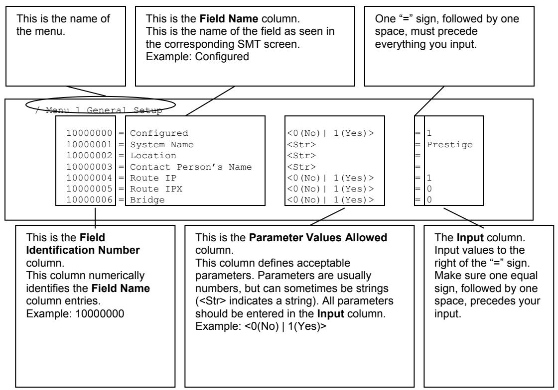
flowchart
graph TD
    A["This is the name of the menu."] --> B["/ Menu 1 General Setup"]
    B --> C["10000000 = Configured"]
    B --> D["10000001 = System Name"]
    B --> E["10000002 = Location"]
    B --> F["10000003 = Contact Person's Name"]
    B --> G["10000004 = Route IP"]
    B --> H["10000005 = Route IPX"]
    B --> I["10000006 = Bridge"]
    J["This is the Field Identification Number column. This column numerically identifies the Field Name column entries. Example: 10000000"] --> K["This column defines acceptable parameters. Parameters are usually numbers, but can sometimes be strings (<Str> indicates a string). All parameters should be entered in the Input column. Example: <0(No) | 1(Yes)>"]
    L["One “=” sign, followed by one space, must precede everything you input."] --> M["<0 (No) | 1 (Yes) ><br><Str><br><Str><br><Str><br><0 (No) | 1 (Yes) ><br><0 (No) | 1 (Yes) ><br><0 (No) | 1 (Yes)>"]
    N["The Input column. Input values to the right of the “=” sign. Make sure one equal sign, followed by one space, precedes your input."] --> O["= 1 = Prestige = 1 = 0 = 0"]
Figure 44-1 Configuration Text File Format: Column Descriptions
DO NOT alter or delete any field except parameters in the Input column.
For more text file examples, refer to the Example Internal SPTGEN Screens Appendix.
44.2.1 Internal SPTGEN File Modification - Important Points to Remember
• Each parameter you enter must be preceded by one “=” sign and one space.
- Some parameters are dependent on others. For example, if you disable the Configured field in menu 1 (see Figure 44-1), then you disable every field in this menu.
- If you enter a parameter that is invalid in the Input column, the Prestige will not save the configuration and the command line will display the Field Identification Number. Figure 44-2, shown next, is an example of what the Prestige displays if you enter a value other than “0” or “1” in the Input column of Field Identification Number 1000000 (refer to Figure 44-1).
field value is not legal error:-1
ROM-t is not saved, error Line ID:10000000
reboot to get the original configuration
Bootbase Version: V2.02 | 2/22/2001 13:33:11
RAM: Size = 8192 Kbytes
FLASH: Intel 8M *2
Figure 44-2 Invalid Parameter Entered: Command Line Example
The Prestige will display the following if you enter parameter(s) that are valid.
Please wait for the system to write SPT text file(ROM-t)...
Bootbase Version: V2.02 | 2/22/2001 13:33:11
RAM: Size = 8192 Kbytes
FLASH: Intel 8M *2
Figure 44-3 Valid Parameter Entered: Command Line Example
44.3 Internal SPTGEN FTP Download Example
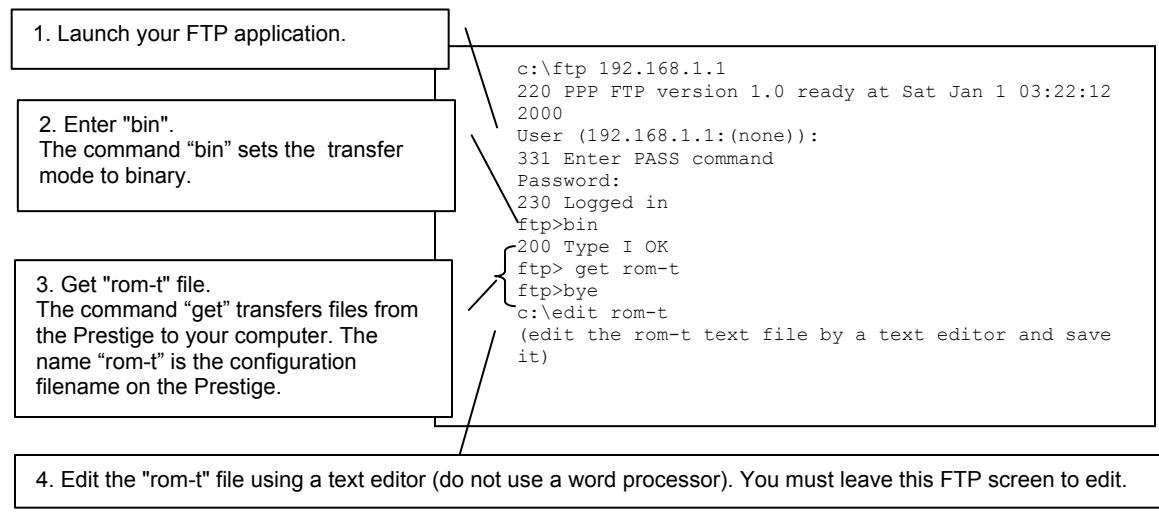
flowchart
graph TD
    A["1. Launch your FTP application."] --> B["2. Enter "bin". The command "bin" sets the transfer mode to binary."]
    B --> C["3. Get "rom-t" file. The command "get" transfers files from the Prestige to your computer. The name "rom-t" is the configuration filename on the Prestige."]
    C --> D["4. Edit the "rom-t" file using a text editor (do not use a word processor). You must leave this FTP screen to edit."]
    D --> E["End"]
Figure 44-4 Internal SPTGEN FTP Download Example
You can rename your “rom-t” file when you save it to your computer but it must be named “rom-t” when you upload it to your Prestige.
44.4 Internal SPTGEN FTP Upload Example
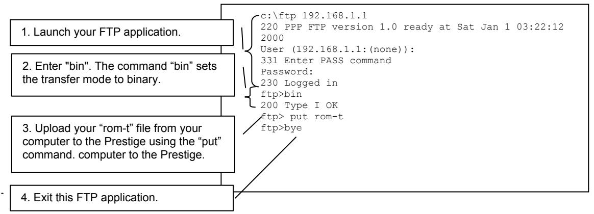
flowchart
graph TD
    A["1. Launch your FTP application."] --> B["2. Enter "bin". The command "bin" sets the transfer mode to binary."]
    B --> C["3. Upload your "rom-t" file from your computer to the Prestige using the "put" command. computer to the Prestige."]
    C --> D["4. Exit this FTP application."]
    A --> E["c:\ftp 192.168.1.1\n220 PPP FTP version 1.0 ready at Sat Jan 1 03:22:12\n2000\nUser (192.168.1.1:(none)):\n331 Enter PASS command\nPassword:\n230 Logged in\nftp>bin\n200 Type I OK\nftp> put rom-t\nftp>bye"]
Figure 44-5 Internal SPTGEN FTP Upload Example
Part XI:
Appendices and Index
This part contains additional background information and an index or key terms.
Appendix A
Troubleshooting
This chapter covers potential problems and the corresponding remedies.
Problems Starting Up the Prestige
Chart A-1 Troubleshooting the Start-Up of Your Prestige
| PROBLEM | CORRECTIVE ACTION | |
| None of the LEDs turn on when I turn on the Prestige. | Make sure that the Prestige's power adaptor is connected to the Prestige and plugged in to an appropriate power source. Check that the Prestige and the power source are both turned on.Turn the Prestige off and on.If the error persists, you may have a hardware problem. In this case, you should contact your vendor. | |
| I cannot access the Prestige via the console port. | 1. Make sure the Prestige is connected to your computer's serial port. | |
| 2. Make sure the communications program is configured correctly.The communications software should be configured as follows: | VT100 terminal emulation. | |
| 9600 bps is the default speed on leaving the factory.Try other speeds in case the speed has been changed. | ||
| No parity, 8 data bits, 1 stop bit, data flow set to none. | ||
Problems with the LAN LED
Chart A-2 Troubleshooting the LAN LED
| PROBLEM | CORRECTIVE ACTION |
| The LAN LEDs do not turn on. | Check your Ethernet cable connections and type (refer to the Compact Guide or Read Me First for details).Check for faulty Ethernet cables. |
| Make sure your computer’s Ethernet Card is working properly. |
Problems with the DSL LED
Chart A-3 Troubleshooting the DSL LED
| PROBLEM | CORRECTIVE ACTION |
| The DSL LED is off. | Check the telephone wire and connections between the Prestige DSL port and the wall jack. |
| Make sure that the telephone company has checked your phone line and set it up for DSL service. | |
| Reset your ADSL line to reinitialize your link to the DSLAM. For details, refer to the Maintenance chapter (web configurator) or the System Information and Diagnosis chapter (SMT). |
Problems with the LAN Interface
Chart A-4 Troubleshooting the LAN Interface
| PROBLEM | CORRECTIVE ACTION |
| I cannot access the Prestige from the LAN. | If the 10M/100M LEDs on the front panel are both off, refer toChart A-2 Troubleshooting the LAN LED.Make sure that the IP address and the subnet mask of the Prestige and your computer(s) are on the same subnet. |
| I cannot ping any computer on the LAN. | If the 10M/100M LEDs on the front panel are both off, refer toChart A-2 Troubleshooting the LAN LED.Make sure that the IP address and the subnet mask of the Prestige and the computers are on the same subnet. |
Problems with the WAN Interface
Chart A-5 Troubleshooting the WAN Interface
| PROBLEM | CORRECTIVE ACTION |
| I cannot get a WAN IP address from the ISP. | The ISP provides the WAN IP address after authenticating you. Authentication may be through the user name and password, the MAC address or the host name.The username and password apply to PPPoE and PPoA encapsulation only. Make sure that you have entered the correct Service Type, User Name and Password (be sure to use the correct casing). Refer to the WAN Setup chapter (web configurator) or the Internet Access chapter (SMT). |
Problems with Internet Access
Chart A-6 Troubleshooting Internet Access
| PROBLEM | CORRECTIVE ACTION |
| I cannot access the Internet. | Make sure the Prestige is turned on and connected to the network.If the DSL LED is off, refer toChart A-3 Troubleshooting the DSL LED.Verify your WAN settings. Refer to theWAN Setupchapter (web configurator) or theInternet Access chapter (SMT).Make sure you entered the correct user name and password.If you use PPPoE pass through (P652H/HW), make sure that bridge is turned on. See theMenu 1 General Setupchapter for details.For wireless stations, check that both the Prestige and wireless station(s) are using the same ESSID, channel and WEP keys (if WEP encryption is activated). |
| Internet connection disconnects. | Check the schedule rules. Refer to theCall Schedulingchapter (SMT).If you use PPPoA or PPPoE encapsulation, check the idle time-out setting. Refer to theWAN chapter (web configurator) or theRemote Node Configurationchapter (SMT).Contact your ISP. |
Problems with the Password
Chart A-7 Troubleshooting the Password
| PROBLEM | CORRECTIVE ACTION |
| I cannot access the Prestige. | The username is “admin”. The default password is “1234”. The Password and Username fields are case-sensitive. Make sure that you enter the correct password and username using the proper casing.If you have changed the password and have now forgotten it, you will need to upload the default configuration file (Refer to the Resetting the Prestige section in the Introducing the Web Configurator chapter). This restores all of the factory defaults including the password. |
Problems with the Web Configurator
Chart A-8 Troubleshooting the Web Configurator
| PROBLEM | CORRECTIVE ACTION |
| I cannot access the web configurator. | Refer toChart A-7 Troubleshooting the Password.Make sure that there is not an SMT console session running.Check that you have enabled web service access. If you have configured a secured client IP address, your computer’s IP address must match it. Refer to the chapter on remote management for details.For WAN access, you must configure remote management to allow server access from the Wan (or all). You must also configure a firewall rule to allow access from the WAN. Refer to the chapters on remote management and firewall for details.Your computer’s and the Prestige’s IP addresses must be on the same subnet for LAN access.If you changed the Prestige’s LAN IP address, then enter the new one as the URL.Remove any filters in SMT menu 3.1 (LAN) or menu 11.5 (WAN) that block web service.See also theProblems with Remote Managementsection. |
Problems with Remote Management
Chart A-9 Troubleshooting Remote Management
| PROBLEM | CORRECTIVE ACTION |
| I cannot remotely manage the Prestige from the LAN or WAN. | Refer to the Remote Management Limitations section in the Firmware and Configuration File Management chapter (SMT) for scenarios when remote management may not be possible. |
| Use the Prestige's WAN IP address when configuring from the WAN.Use the Prestige's LAN IP address when configuring from the LAN. | |
| Refer to Chart A-4 Troubleshooting the LAN Interface for instructions on checking your LAN connection. | |
| Refer to the Problems with the WAN Interface section for instructions on checking your WAN connection. | |
| See also the Problems with the Web Configurator section. |
Appendix B
IP Subnetting
IP Addressing
Routers “route” based on the network number. The router that delivers the data packet to the correct destination host uses the host ID.
IP Classes
An IP address is made up of four octets (eight bits), written in dotted decimal notation, for example, 192.168.1.1. IP addresses are categorized into different classes. The class of an address depends on the value of its first octet.
Class “A” addresses have a 0 in the left most bit. In a class “A” address the first octet is the network number and the remaining three octets make up the host ID.
Class “B” addresses have a 1 in the left most bit and a 0 in the next left most bit. In a class “B” address the first two octets make up the network number and the two remaining octets make up the host ID.
Class “C” addresses begin (starting from the left) with 1 1 0. In a class “C” address the first three octets make up the network number and the last octet is the host ID.
Class “D” addresses begin with 1 1 1 0. Class “D” addresses are used for multicasting. (There is also a class “E” address. It is reserved for future use.)
Chart B-1 Classes of IP Addresses
| IP ADDRESS: | OCTET 1 | OCTET 2 | OCTET 3 | OCTET 4 | |
| Class A | 0 | Network number | Host ID | Host ID | Host ID |
| Class B | 10 | Network number | Network number | Host ID | Host ID |
| Class C | 110 | Network number | Network number | Network number | Host ID |
Host IDs of all zeros or all ones are not allowed.
Therefore:
A class “C” network (8 host bits) can have 2^8-2 or 254 hosts.
A class “B” address (16 host bits) can have 2^16-2 or 65534 hosts.
A class “A” address (24 host bits) can have 2^24-2 hosts (approximately 16 million hosts).
Since the first octet of a class “A” IP address must contain a “0”, the first octet of a class “A” address can have a value of 0 to 127.
Similarly the first octet of a class “B” must begin with “10”, therefore the first octet of a class “B” address has a valid range of 128 to 191. The first octet of a class “C” address begins with “110”, and therefore has a range of 192 to 223.
Chart B-2 Allowed IP Address Range By Class
| CLASS | ALLOWED RANGE OF FIRST OCTET (BINARY) | ALLOWED RANGE OF FIRST OCTET (DECIMAL) |
| Class A | 00000000 to 01111111 | 0 to 127 |
| Class B | 10000000 to 10111111 | 128 to 191 |
| Class C | 11000000 to 11011111 | 192 to 223 |
| Class D | 11100000 to 11101111 | 224 to 239 |
Subnet Masks
A subnet mask is used to determine which bits are part of the network number, and which bits are part of the host ID (using a logical AND operation). A subnet mask has 32 bits; each bit of the mask corresponds to a bit of the IP address. If a bit in the subnet mask is a “1” then the corresponding bit in the IP address is part of the network number. If a bit in the subnet mask is “0” then the corresponding bit in the IP address is part of the host ID.
Subnet masks are expressed in dotted decimal notation just as IP addresses are. The “natural” masks for class A, B and C IP addresses are as follows.
Chart B-3 "Natural" Masks
| CLASS | NATURAL MASK |
| A | 255.0.0.0 |
| B | 255.255.0.0 |
| C | 255.255.255.0 |
Subnetting
With subnetting, the class arrangement of an IP address is ignored. For example, a class C address no longer has to have 24 bits of network number and 8 bits of host ID. With subnetting, some of the host ID bits are converted into network number bits. By convention, subnet masks always consist of a continuous sequence
of ones beginning from the left most bit of the mask, followed by a continuous sequence of zeros, for a total number of 32 bits.
Since the mask is always a continuous number of ones beginning from the left, followed by a continuous number of zeros for the remainder of the 32 bit mask, you can simply specify the number of ones instead of writing the value of each octet. This is usually specified by writing a “/” followed by the number of bits in the mask after the address.
For example, 192.1.1.0 /25 is equivalent to saying 192.1.1.0 with mask 255.255.255.128.
The following table shows all possible subnet masks for a class “C” address using both notations.
Chart B-4 Alternative Subnet Mask Notation
| SUBNET MASK IP ADDRESS | SUBNET MASK “1” BITS | LAST OCTET BIT VALUE |
| 255.255.255.0 | /24 | 0000 0000 |
| 255.255.255.128 | /25 | 1000 0000 |
| 255.255.255.192 | /26 | 1100 0000 |
| 255.255.255.224 | /27 | 1110 0000 |
| 255.255.255.240 | /28 | 1111 0000 |
| 255.255.255.248 | /29 | 1111 1000 |
| 255.255.255.252 | /30 | 1111 1100 |
The first mask shown is the class “C” natural mask. Normally if no mask is specified it is understood that the natural mask is being used.
Example: Two Subnets
As an example, you have a class "C" address 192.168.1.0 with subnet mask of 255.255.255.0.
| NETWORK NUMBER | HOST ID | |
| IP Address | 192.168.1. | 0 |
| IP Address (Binary) | 11000000.10101000.00000001. | 00000000 |
| Subnet Mask | 255.255.255. | 0 |
| Subnet Mask (Binary) | 11111111.11111111.11111111. | 00000000 |
The first three octets of the address make up the network number (class “C”). You want to have two separate networks.
Divide the network 192.168.1.0 into two separate subnets by converting one of the host ID bits of the IP address to a network number bit. The “borrowed” host ID bit can be either “0” or “1” thus giving two subnets; 192.168.1.0 with mask 255.255.255.128 and 192.168.1.128 with mask 255.255.255.128.
In the following charts, shaded/bolded last octet bit values indicate host ID bits “borrowed” to form network ID bits. The number of “borrowed” host ID bits determines the number of subnets you can have. The remaining number of host ID bits (after “borrowing”) determines the number of hosts you can have on each subnet.
Chart B-5 Subnet 1
| NETWORK NUMBER | LAST OCTET BIT VALUE | ||
| IP Address | 192.168.1. | 0 | |
| IP Address (Binary) | 11000000.10101000.00000001. | 00000000 | |
| Subnet Mask | 255.255.255. | 128 | |
| Subnet Mask (Binary) | 11111111.11111111.11111111. | 10000000 | |
| Subnet Address: 192.168.1.0 | Lowest Host ID: 192.168.1.1 | ||
| Broadcast Address: 192.168.1.127 | Highest Host ID: 192.168.1.126 | ||
Chart B-6 Subnet 2
| NETWORK NUMBER | LAST OCTET BIT VALUE | ||
| IP Address | 192.168.1. | 128 | |
| IP Address (Binary) | 11000000.10101000.00000001. | 10000000 | |
| Subnet Mask | 255.255.255. | 128 | |
| Subnet Mask (Binary) | 11111111.11111111.11111111. | 10000000 | |
| Subnet Address: 192.168.1.128 | Lowest Host ID: 192.168.1.129 | ||
| Broadcast Address: 192.168.1.255 | Highest Host ID: 192.168.1.254 | ||
The remaining 7 bits determine the number of hosts each subnet can have. Host IDs of all zeros represent the subnet itself and host IDs of all ones are the broadcast address for that subnet, so the actual number of hosts available on each subnet in the example above is 2^7-2 or 126 hosts for each subnet.
192.168.1.0 with mask 255.255.255.128 is the subnet itself, and 192.168.1.127 with mask 255.255.255.128 is the directed broadcast address for the first subnet. Therefore, the lowest IP address that can be assigned to an
actual host for the first subnet is 192.168.1.1 and the highest is 192.168.1.126. Similarly the host ID range for the second subnet is 192.168.1.129 to 192.168.1.254.
Example: Four Subnets
The above example illustrated using a 25-bit subnet mask to divide a class “C” address space into two subnets. Similarly to divide a class “C” address into four subnets, you need to “borrow” two host ID bits to give four possible combinations of 00, 01, 10 and 11. The subnet mask is 26 bits (11111111.11111111.11111111.11000000) or 255.255.255.192. Each subnet contains 6 host ID bits, giving 2^6 -2 or 62 hosts for each subnet (all 0’s is the subnet itself, all 1’s is the broadcast address on the subnet).
Chart B-7 Subnet 1
| NETWORK NUMBER | LAST OCTET BIT VALUE | ||
| IP Address | 192.168.1. | 0 | |
| IP Address (Binary) | 11000000.10101000.00000001. | 00000000 | |
| Subnet Mask (Binary) | 11111111.11111111.11111111. | 11000000 | |
| Subnet Address: 192.168.1.0 | Lowest Host ID: 192.168.1.1 | ||
| Broadcast Address: 192.168.1.63 | Highest Host ID: 192.168.1.62 | ||
Chart B-8 Subnet 2
| NETWORK NUMBER | LAST OCTET BIT VALUE | ||
| IP Address | 192.168.1. | 64 | |
| IP Address (Binary) | 11000000.10101000.00000001. | 01000000 | |
| Subnet Mask (Binary) | 11111111.11111111.11111111. | 11000000 | |
| Subnet Address: 192.168.1.64 | Lowest Host ID: 192.168.1.65 | ||
| Broadcast Address: 192.168.1.127 | Highest Host ID: 192.168.1.126 | ||
Chart B-9 Subnet 3
| NETWORK NUMBER | LAST OCTET BIT VALUE | ||
| IP Address | 192.168.1. | 128 | |
| IP Address (Binary) | 11000000.10101000.00000001. | 10000000 | |
| Subnet Mask (Binary) | 11111111.11111111.11111111. | 11000000 | |
| Subnet Address: 192.168.1.128 | Lowest Host ID: 192.168.1.129 | ||
| Broadcast Address: 192.168.1.191 | Highest Host ID: 192.168.1.190 | ||
Chart B-10 Subnet 4
| NETWORK NUMBER | LAST OCTET BIT VALUE | ||
| IP Address | 192.168.1. | 192 | |
| IP Address (Binary) | 11000000.10101000.00000001. | 11000000 | |
| Subnet Mask (Binary) | 11111111.11111111.11111111. | 11000000 | |
| Subnet Address: 192.168.1.192 | Lowest Host ID: 192.168.1.193 | ||
| Broadcast Address: 192.168.1.255 | Highest Host ID: 192.168.1.254 | ||
Example Eight Subnets
Similarly use a 27-bit mask to create 8 subnets (001, 010, 011, 100, 101, 110).
The following table shows class C IP address last octet values for each subnet.
Chart B-11 Eight Subnets
| SUBNET | SUBNET ADDRESS | FIRST ADDRESS | LAST ADDRESS | BROADCAST ADDRESS |
| 1 | 0 | 1 | 30 | 31 |
| 2 | 32 | 33 | 62 | 63 |
| 3 | 64 | 65 | 94 | 95 |
| 4 | 96 | 97 | 126 | 127 |
| 5 | 128 | 129 | 158 | 159 |
| 6 | 160 | 161 | 190 | 191 |
| 7 | 192 | 193 | 222 | 223 |
| 8 | 224 | 223 | 254 | 255 |
The following table is a summary for class “C” subnet planning.
Chart B-12 Class C Subnet Planning
| NO. “BORROWED” HOST BITS | SUBNET MASK | NO. SUBNETS | NO. HOSTS PER SUBNET |
| 1 | 255.255.255.128 (/25) | 2 | 126 |
| 2 | 255.255.255.192 (/26) | 4 | 62 |
| 3 | 255.255.255.224 (/27) | 8 | 30 |
| 4 | 255.255.255.240 (/28) | 16 | 14 |
| 5 | 255.255.255.248 (/29) | 32 | 6 |
| 6 | 255.255.255.252 (/30) | 64 | 2 |
| 7 | 255.255.255.254 (/31) | 128 | 1 |
Subnetting With Class A and Class B Networks.
For class “A” and class “B” addresses the subnet mask also determines which bits are part of the network number and which are part of the host ID.
A class “B” address has two host ID octets available for subnetting and a class “A” address has three host ID octets (see Chart B-1) available for subnetting.
The following table is a summary for class “B” subnet planning.
Chart B-13 Class B Subnet Planning
| NO. “BORROWED” HOST BITS | SUBNET MASK | NO. SUBNETS | NO. HOSTS PER SUBNET |
| 1 | 255.255.128.0 (/17) | 2 | 32766 |
| 2 | 255.255.192.0 (/18) | 4 | 16382 |
| 3 | 255.255.224.0 (/19) | 8 | 8190 |
| 4 | 255.255.240.0 (/20) | 16 | 4094 |
| 5 | 255.255.248.0 (/21) | 32 | 2046 |
| 6 | 255.255.252.0 (/22) | 64 | 1022 |
| 7 | 255.255.254.0 (/23) | 128 | 510 |
| 8 | 255.255.255.0 (/24) | 256 | 254 |
| 9 | 255.255.255.128 | 512 | 126 |
Chart B-13 Class B Subnet Planning
| NO. “BORROWED” HOST BITS | SUBNET MASK | NO. SUBNETS | NO. HOSTS PER SUBNET |
| (/25) | |||
| 10 | 255.255.255.192 (/26) | 1024 | 62 |
| 11 | 255.255.255.224 (/27) | 2048 | 30 |
| 12 | 255.255.255.240 (/28) | 4096 | 14 |
| 13 | 255.255.255.248 (/29) | 8192 | 6 |
| 14 | 255.255.255.252 (/30) | 16384 | 2 |
| 15 | 255.255.255.254 (/31) | 32768 | 1 |
Appendix C
Wireless LAN and IEEE 802.11
A wireless LAN (WLAN) provides a flexible data communications system that you can use to access various services (navigating the Internet, email, printer services, etc.) without the any expensive network cabling infrastructure. In effect a wireless LAN environment provides you the freedom to stay connected to the network while in the coverage area.
Benefits of a Wireless LAN
- Access to network services in areas otherwise hard or expensive to wire, such as historical buildings, buildings with asbestos materials and classrooms.
- Doctors and nurses can access a complete patient's profile on a handheld or notebook computer upon entering a patient's room.
- It allows flexible workgroups a lower total cost of ownership for networks that are frequently reconfigured.
- Conference room users can access the network as they move from meeting to meeting- accessing up-to-date information that facilitates the ability to communicate decisions “on the fly”.
- It provides campus-wide networking coverage, allowing enterprises the roaming capability to set up easy-to-use wireless networks that transparently covers an entire campus.
IEEE 802.11
The 1997 completion of the IEEE 802.11 standard for wireless LANs (WLANs) was a first important step in the evolutionary development of wireless networking technologies. The standard was developed to maximize interoperability between differing brands of wireless LANs and to introduce a variety of performance improvements and benefits. On September 16, 1999, the 802.11b provided much higher data rates of up to 11Mbps, while maintaining the 802.11 protocol.
The IEEE 802.11 specifies three different transmission methods for the PHY, the layer responsible for transferring data between nodes. Two of the methods use spread spectrum RF signals, Direct Sequence Spread Spectrum (DSSS) and Frequency-Hopping Spread Spectrum (FHSS), in the 2.4 to 2.4825 GHz unlicensed ISM (Industrial, Scientific and Medical) band. The third method is infrared technology, using very high frequencies, just below visible light in the electromagnetic spectrum to carry data.
Ad-hoc Wireless LAN Configuration
The simplest WLAN configuration is an independent (Ad-hoc) WLAN that connects a set of computers with wireless nodes or stations (STA), which is called a Basic Service Set (BSS). In the most basic form, a wireless LAN connects a set of computers with wireless adapters. Any time two or more wireless adapters are within range of each other, they can set up an independent network, which is commonly referred to as an Ad-hoc network or Independent Basic Service Set (IBSS). See the following diagram of an example of an Ad-hoc wireless LAN.
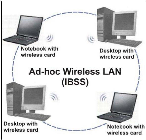
flowchart
graph TD
    A["Laptop"] -->|Notebook with wireless card| B["Desktop with wireless card"]
    B -->|Notebook with wireless card| C["Desktop with wireless card"]
    C -->|Notebook with wireless card| D["Laptop"]
    D -->|Notebook with wireless card| E["Desktop with wireless card"]
    E -->|Notebook with wireless card| F["Laptop"]
    F -->|Notebook with wireless card| G["Desktop with wireless card"]
    G -->|Notebook with wireless card| H["Laptop"]
    H -->|Notebook with wireless card| I["Desktop with wireless card"]
    I -->|Notebook with wireless card| J["Laptop"]
    J -->|Notebook with wireless card| K["Desktop with wireless card"]
    K -->|Notebook with wireless card| L["Laptop"]
    L -->|Notebook with wireless card| M["Desktop with wireless card"]
    M -->|Notebook with wireless card| N["Laptop"]
    N -->|Notebook with wireless card| O["Desktop with wireless card"]
    O -->|Notebook with wireless card| P["Laptop"]
    P -->|Notebook with wireless card| Q["Desktop with wireless card"]
    Q -->|Notebook with wireless card| R["Laptop"]
    R -->|Notebook with wireless card| S["Desktop with wireless card"]
    S -->|Notebook with wireless card| T["Laptop"]
    T -->|Notebook with wireless card| U["Desktop with wireless card"]
    U -->|Notebook with wireless card| V["Laptop"]
    V -->|Notebook with wireless card| W["Desktop with wireless card"]
    W -->|Notebook with wireless card| X["Laptop"]
    X -->|Notebook with wireless card| Y["Desktop with wireless card"]
    Y -->|Notebook with wireless card| Z["Laptop"]
    Z -->|Notebook with wireless card| AA["Desktop with wireless card"]
    AA -->|Notebook with wireless card| AB["Laptop"]
    AB -->|Notebook with wireless card| AC["Desktop with wireless card"]
    AC -->|Notebook with wireless card| AD["Laptop"]
    AD -->|Notebook with wireless card| AE["Desktop with wireless card"]
    AE -->|Notebook with wireless card| AF["Laptop"]
    AF -->|Notebook with wireless card| AG["Desktop with wireless card"]
    AG -->|Notebook with wireless card| AH["Laptop"]
    AH -->|Notebook with wireless card| AI["Desktop with wireless card"]
    AI -->|Notebook with wireless card| AJ["Laptop"]
    AJ -->|Notebook with wireless card| AK["Desktop with wireless card"]
    AK -->|Notebook with wireless card| AL["Laptop"]
    AL -->|Notebook with wireless card| AM["Desktop with wireless card"]
    AM -->|Notebook with wireless card| AN["Laptop"]
    AN -->|Notebook with wireless card| AO["Desktop with wireless card"]
    AO -->|Notebook with wireless card| AP["Laptop"]
    AP -->|Notebook with wireless card| AQ["Desktop with wireless card"]
    AQ -->|Notebook with wireless card| AR["Laptop"]
    AR -->|Notebook with wireless card| AS["Desktop with wireless card"]
    AS -->|Notebook with wireless card| AT["Laptop"]
    AT -->|Notebook with wireless card| AU["Desktop with wireless card"]
    AU -->|Notebook with wireless card| AV["Laptop"]
    AV -->|Notebook with wireless card| AW["Desktop with wireless card"]
    AW -->|Notebook with wireless card| AX["Laptop"]
    AX -->|Notebook with wireless card| AY["Desktop with wireless card"]
    AY -->|Notebook with wireless card| AZ["Laptop"]
    AZ -->|Notebook with wireless card| BA["Desktop with wireless card"]
    BA -->|Notebook with wireless card| BB["Laptop"]
    BB -->|Notebook with wireless card| BC["Desktop with wireless card"]
    BC -->|Notebook with wireless card| BD["Laptop"]
    BD -->|Notebook with wireless card| BE["Desktop with wireless card"]
    BE -->|Notebook with wireless card| BF["Laptop"]
    BF -->|Notebook with wireless card| BG["Desktop with wireless card"]
    BG -->|Notebook with wireless card| BH["Laptop"]
    BH -->|Notebook with wireless card| BI["Desktop with wireless card"]
    BI -->|Notebook with wireless card| BJ["Laptop"]
    BJ -->|Notebook with wireless card| BK["Desktop with wireless card"]
    BK -->|Notebook with wireless card| BL["Laptop"]
    BL -->|Notebook with wireless card| BM["Desktop with wireless card"]
    BM -->|Notebook with wireless card| BN["Laptop"]
    BN -->|Notebook with wireless card| BO["Desktop with wireless card"]
    BO -->|Notebook with wireless card| BP["Laptop"]
    BP -->|Notebook with wireless card| BQ["Desktop with wireless card"]
    BQ -->|Notebook with wireless card| BR["Laptop"]
    BR -->|Notebook with wireless card| BS["Desktop with wireless card"]
    BS -->|Notebook with wireless card| BT["Laptop"]
    BT -->|Notebook with wireless card| BU["Desktop with wireless card"]
    BU -->|Notebook with wireless card| BV["Laptop"]
    BV -->|Notebook with wireless card|
    BV -->|Notebook with wireless card|
Diagram C-1 Peer-to-Peer Communication in an Ad-hoc Network
Infrastructure Wireless LAN Configuration
For Infrastructure WLANs, multiple access points (APs) link the WLAN to the wired network and allow users to efficiently share network resources. The Access Points not only provide communication with the wired network but also mediate wireless network traffic in the immediate neighborhood. Multiple access points can provide wireless coverage for an entire building or campus. All communications between stations or between a station and a wired network client go through the access point.
The Extended Service Set (ESS) shown in the next figure consists of a series of overlapping BSSs (each containing an access point) connected together by means of a Distribution System (DS). Although the DS could be any type of network, it is almost invariably an Ethernet LAN. Mobile nodes can roam between access points and seamless campus-wide coverage is possible.
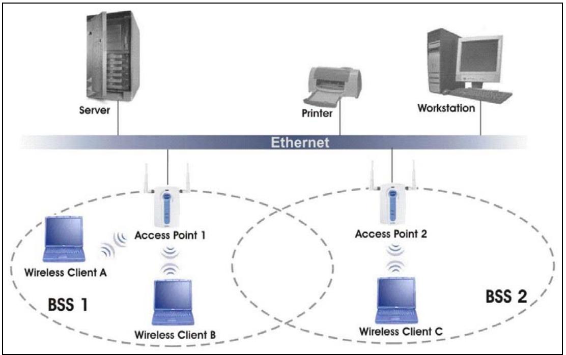
flowchart
graph TD
    Server["Server"] -->|Ethernet| Internet1["Access Point 1"]
    Internet1 -->|BSS 1| WirelessClientA["Wireless Client A"]
    Internet1 -->|BSS 1| WirelessClientB["Wireless Client B"]
    Internet1 -->|BSS 1| WirelessClientC["Wireless Client C"]
    Internet2["Printer"] -->|Ethernet| Internet2["Access Point 2"]
    Internet2 -->|BSS 2| WirelessClientC
    Internet2 -->|BSS 2| WirelessClientB
    Internet2 -->|BSS 2| WirelessClientC
    Workstation["Workstation"] -->|Ethernet| Internet2
    Workstation -->|BSS 2| WirelessClientC
Diagram C-2 ESS Provides Campus-Wide Coverage
Appendix D PPPoE
PPPoE in Action
An ADSL modem bridges a PPP session over Ethernet (PPP over Ethernet, RFC 2516) from your PC to an ATM PVC (Permanent Virtual Circuit) which connects to a xDSL Access Concentrator where the PPP session terminates (see the next figure). One PVC can support any number of PPP sessions from your LAN. PPPoE provides access control and billing functionality in a manner similar to dial-up services using PPP.
Benefits of PPPoE
PPPoE offers the following benefits:
- It provides you with a familiar dial-up networking (DUN) user interface.
- It lessens the burden on the carriers of provisioning virtual circuits all the way to the ISP on multiple switches for thousands of users. For GSTN (PSTN and ISDN), the switching fabric is already in place.
- It allows the ISP to use the existing dial-up model to authenticate and (optionally) to provide differentiated services.
Traditional Dial-up Scenario
The following diagram depicts a typical hardware configuration where the PCs use traditional dial-up networking.
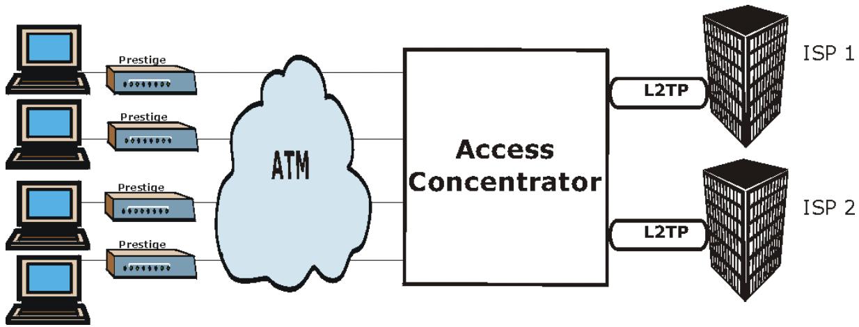
flowchart
graph LR
    A["Computer"] --> B["Prestige"]
    C["Computer"] --> D["Prestige"]
    E["Computer"] --> F["Prestige"]
    G["Computer"] --> H["Prestige"]
    B --> I["ATM"]
    D --> I
    F --> I
    H --> I
    I --> J["Access Concentrator"]
    J --> K["L2TP"]
    J --> L["L2TP"]
    K --> M["ISP 1"]
    L --> N["ISP 2"]
Diagram D-1 Single-PC per Router Hardware Configuration
How PPPoE Works
The PPPoE driver makes the Ethernet appear as a serial link to the PC and the PC runs PPP over it, while the modem bridges the Ethernet frames to the Access Concentrator (AC). Between the AC and an ISP, the AC is acting as a L2TP (Layer 2 Tunneling Protocol) LAC (L2TP Access Concentrator) and tunnels the PPP frames to the ISP. The L2TP tunnel is capable of carrying multiple PPP sessions.
With PPPoE, the VC (Virtual Circuit) is equivalent to the dial-up connection and is between the modem and the AC, as opposed to all the way to the ISP. However, the PPP negotiation is between the PC and the ISP.
Prestige as a PPPoE Client
When using the Prestige as a PPPoE client, the PCs on the LAN see only Ethernet and are not aware of PPPoE. This alleviates the administrator from having to manage the PPPoE clients on the individual PCs.
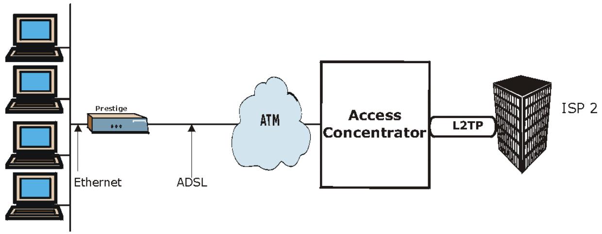
flowchart
graph LR
    A["Computer"] --> B["Prestige"]
    B --> C["ATM"]
    C --> D["Access Concentrator"]
    D --> E["L2TP"]
    E --> F["ISP 2"]
    G["Ethernet"] --> B
    H["ADSL"] --> C
Diagram D-2 Prestige as a PPPoE Client
Appendix E
Virtual Circuit Topology
ATM is a connection-oriented technology, meaning that it sets up virtual circuits over which end systems communicate. The terminology for virtual circuits is as follows:
- Virtual Channel Logical connections between ATM switches
- Virtual Path A bundle of virtual channels
● Virtual Circuit A series of virtual paths between circuit end points virtual circuit
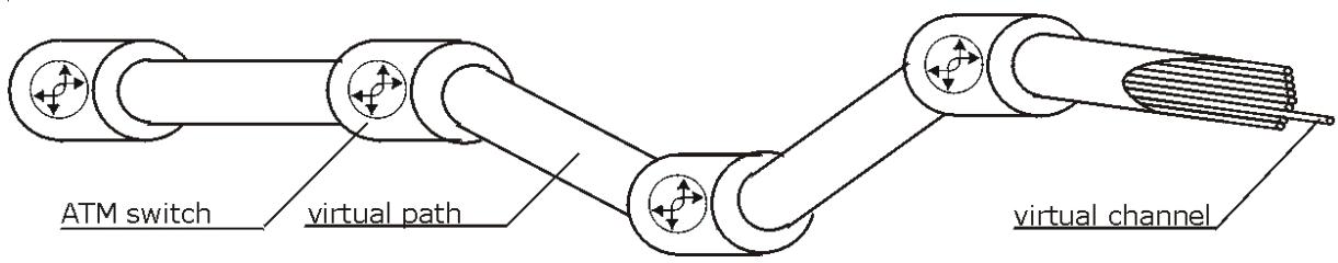
Diagram E-1 Virtual Circuit Topology
Think of a virtual path as a cable that contains a bundle of wires. The cable connects two points and wires within the cable provide individual circuits between the two points. In an ATM cell header, a VPI (Virtual Path Identifier) identifies a link formed by a virtual path; a VCI (Virtual Channel Identifier) identifies a channel within a virtual path.
The VPI and VCI identify a virtual path, that is, termination points between ATM switches. A series of virtual paths make up a virtual circuit.
Your service provider should supply you with VPI/VCI numbers.
Appendix F
Power Adaptor Specifications
Prestige 652R-11; Prestige 652R-13
| NORTH AMERICAN PLUG STANDARDS | |
| AC Power Adapter Model | DV-1215A |
| Input Power | AC120Volts/60Hz/30W |
| Output Power | AC12Volts/1.25A |
| Power Consumption | 11 W |
| Safety Standards | UL, CUL, CSA (UL 1310, CSA C22.2 No.223) |
| NORTH AMERICAN PLUG STANDARDS | |
| AC Power Adapter Model | AA-121A25 |
| Input Power | AC120Volts/60Hz/19W |
| Output Power | AC 12Volts/ 1.25A |
| Power Consumption | 11W |
| Safety Standards | UL, CUL (UL 1310, CSA C22.2 No.223) |
| EUROPEAN PLUG STANDARDS | |
| AC Power Adapter Model | AA-121A3BN |
| Input Power | AC230Volts/50Hz/140mA |
| Output Power | AC12Volts/1.3A |
| Power Consumption | 11W |
| Safety Standards | ITS-GS, CE (EN 60950) |
Prestige 652H-31/-33/-37; Prestige 652H/HW-31/-33/-37
| NORTH AMERICAN PLUG STANDARDS | |
| AC Power Adapter Model | DV-1215A |
| Input Power | AC120Volts/60Hz/30W |
| Output Power | AC12Volts/1.25A |
| Power Consumption | 14 W |
| Safety Standards | UL, CUL, CSA (UL 1310, CSA C22.2 No.223) |
| NORTH AMERICAN PLUG STANDARDS | |
| AC Power Adapter Model | AA-121A25 |
| Input Power | AC120Volts/60Hz/19W |
| Output Power | AC 12Volts/ 1.25A |
| Power Consumption | 14W |
| Safety Standards | UL, CUL (UL 1310, CSA C22.2 No.223) |
| EUROPEAN PLUG STANDARDS | |
| AC Power Adapter Model | AA-121A3BN |
| Input Power | AC230Volts/50Hz/140mA |
| Output Power | AC12Volts/1.3A |
| Power Consumption | 14W |
| Safety Standards | ITS-GS, CE (EN 60950) |
| UNITED KINGDOM PLUG STANDARDS | |
| AC Power Adapter Model | AA-121A3D |
| Input Power | AC230Volts/50Hz/140mA |
| Output Power | AC12Volts/1.3A |
| Power Consumption | 14W |
| Safety Standards | ITS-GS, CE (EN 60950) |
Appendix G
Example Internal SPTGEN Screens
This appendix covers Prestige Internal SPTGEN screens.
Abbreviations Used in the Example Internal SPTGEN Screens Table
| ABBREVIATION | MEANING |
| FIN | Field Identification Number (not seen in SMT screens) |
| FN | Field Name |
| PVA | Parameter Values Allowed |
| INPUT | An example of what you may enter |
| * | Applies to the P652H/HW. |
The following are Internal SPTGEN screens associated with the SMT screens of your Prestige.
Example Internal SPTGEN Screens Table
| / MENU 1 GENERAL SETUP (SMT MENU 1) | |||
| FIN | FN | PVA | INPUT |
| 10000000 = | Configured | <0(No) | 1(Yes)> | = 0 |
| 10000001 = | System Name | = Prestige | |
| 10000002 = | Location | = | |
| 10000003 = | Contact Person's Name | = | |
| 10000004 = | Route IP | <0(No) | 1(Yes)> | = 1 |
| 10000006 = | Bridge | <0(No) | 1(Yes)> | = 0 |
| / MENU 3.1 GENERAL ETHERNET SETUP (SMT MENU 3.1) | |||
| FIN | FN | PVA | INPUT |
| 30100001 = | Input Protocol filters Set 1 |  | |
| 30100002 = | Input Protocol filters Set 2 | ||
| 30100003 = | Input Protocol filters Set 3 | ||
| 30100004 = | Input Protocol filters Set 4 | = 256 | |
| 30100005 = | Input device filters Set 1 | = 256 | |
| 30100006 = | Input device filters Set 2 | = 256 | |
| 30100007 = | Input device filters Set 3 | = 256 | |
| 30100008 = | Input device filters Set 4 | = 256 | |
| 30100009 = | Output protocol filters Set 1 | = 256 | |
| 30100010 = | Output protocol filters Set 2 | = 256 | |
| 30100011 = | Output protocol filters Set 3 | = 256 | |
| 30100012 = | Output protocol filters Set 4 | = 256 | |
| 30100013 = | Output device filters Set 1 | = 256 | |
| 30100014 = | Output device filters Set 2 | = 256 | |
| 30100015 = | Output device filters Set 3 | = 256 | |
| 30100016 = | Output device filters Set 4 | = 256 | |
| / MENU 3.2 TCP/IP AND DHCP ETHERNET SETUP (SMT MENU 3.2) | |||
| FIN | FN | PVA | INPUT |
| 30200001 = | DHCP | <0(None) | 1(Server) | 2(Relay)> | = 0 |
| 30200002 = | Client IP Pool Starting Address | = 192.168 | |
| 30200003 = | Size of Client IP Pool | = 32 | |
| 30200004 = | Primary DNS Server | = 0.0.0.0 | |
| 30200005 = | Secondary DNS Server | = 0.0.0.0 | |
| 30200006 = | Remote DHCP Server | = 0.0.0.0 | |
| 30200008 = | IP Address | = 172.21.2.200 | |
| 30200009 = | IP Subnet Mask | = 16 | |
| 30200010 = | RIP Direction | <0(None) | 1(Both) | 2(In Only) | 3(Out Only)> | = 0 |
| 30200011 = | Version | <0(Rip-1) | 1(Rip-2B) |2(Rip-2M)> | = 0 |
| 30200012 = | Multicast | <0(IGMP-v2) | 1(IGMP-v1) | 2(None)> | = 2 |
| 30200013 = | IP Policies Set 1 (1~12) | = 256 | |
| 30200014 = | IP Policies Set 2 (1~12) | = 256 | |
| 30200015 = | IP Policies Set 3 (1~12) | = 256 | |
| 30200016 = | IP Policies Set 4 (1~12) | = 256 | |
| /MENU 3.2.1 IP ALIAS SETUP (SMT MENU 3.2.1) | |||
| FIN | FN | PVA | INPUT |
| 30201001 = | IP Alias 1 | <0(No) | 1(Yes)> | = 0 |
| 30201002 = | IP Address | = 0.0.0.0 | |
| 30201003 = | IP Subnet Mask | = 0 | |
| 30201004 = | RIP Direction | <0(None) | 1(Both) | 2(In Only) | 3(Out Only)> | = 0 |
| 30201005 = | Version | <0(Rip-1) | 1(Rip-2B) |2(Rip-2M)> | = 0 |
| 30201006 = | IP Alias #1 Incoming protocol filters Set 1 | = 256 | |
| 30201007 = | IP Alias #1 Incoming protocol filters Set 2 | = 256 | |
| 30201008 = | IP Alias #1 Incoming protocol filters Set 3 | = 256 | |
| 30201009 = | IP Alias #1 Incoming protocol filters Set 4 | = 256 | |
| 30201010 = | IP Alias #1 Outgoing protocol filters Set 1 | = 256 | |
| 30201011 = | IP Alias #1 Outgoing protocol filters Set 2 | = 256 | |
| 30201012 = | IP Alias #1 Outgoing protocol filters Set 3 | = 256 | |
| 30201013 = | IP Alias #1 Outgoing protocol filters Set 4 | = 256 | |
| 30201014 = | IP Alias 2 <0(No) | 1(Yes)> | = 0 | |
| 30201015 = | IP Address | = 0.0.0.0 | |
| 30201016 = | IP Subnet Mask | = 0 | |
| 30201017 = | RIP Direction | <0(None) | 1(Both) | 2(In Only) | 3(Out Only)> | = 0 |
| 30201018 = | Version | <0(Rip-1) | 1(Rip-2B) |2(Rip-2M)> | = 0 |
| 30201019 = | IP Alias #2 Incoming protocol filters Set 1 | = 256 | |
| 30201020 = | IP Alias #2 Incoming protocol filters Set 2 | = 256 | |
| 30201021 = | IP Alias #2 Incoming protocol filters Set 3 | = 256 | |
| 30201022 = | IP Alias #2 Incoming protocol filters Set 4 | = 256 | |
| 30201023 = | IP Alias #2 Outgoing protocol filters Set 1 | = 256 | |
| 30201024 = | IP Alias #2 Outgoing protocol filters Set 2 | = 256 | |
| 30201025 = | IP Alias #2 Outgoing protocol filters Set 3 | = 256 | |
| 30201026 = | IP Alias #2 Outgoing protocol filters Set 4 | = 256 | |
| */ MENU 3.5 WIRELESS LAN SETUP (SMT MENU 3.5) | |||
| 30500001 = | ESSID | Wireless | |
| 30500002 = | Hide ESSID | <0(No) | 1(Yes)> | = 0 |
| 30500003 = | Channel ID | <1|2|3|4|5|6|7|8|9|10|11|12|13> | = 1 |
| 30500004 = | RTS Threshold | <0 ~ 2432> | = 2432 |
| 30500005 = | FRAG. Threshold | <256 ~ 2432> | = 2432 |
| 30500006 = | WEP | <0(DISABLE) | 1(64-bit WEP) | 2(128-bit WEP)> | = 0 |
| 30500007 = | Default Key | <1|2|3|4> | = 0 |
| 30500008 = | WEP Key1 | = | |
| 30500009 = | WEP Key2 | = | |
| 30500010 = | WEP Key3 | = | |
| 30500011 = | WEP Key4 | = | |
| */ MENU 3.5.1 WLAN MAC ADDRESS FILTER (SMT MENU 3.5.1) | |||
| 30501001 = | Mac Filter Active | <0(No) | 1(Yes)> | = 0 |
| 30501002 = | Filter Action | <0(Allow) | 1(Deny)> | = 0 |
| 30501003 = | Address 1 | = 00:00:00:00:00:00 | |
| 30501004 = | Address 2 | = 00:00:00:00:00:00 | |
| 30501005 = | Address 3 | = 00:00:00:00:00:00 | |
| Continued | ... | ... | |
| 30501034 = | Address 32 | = 00:00:00:00:00:00 | |
| / MENU 4 INTERNET ACCESS SETUP (SMT MENU 4) | |||
| FIN | FN | PVA | INPUT |
| 40000000 = | Configured | <0(No) | 1(Yes)> | = 1 |
| 40000001 = | ISP | <0(No) | 1(Yes)> | = 1 |
| 40000002 = | Active | <0(No) | 1(Yes)> | = 1 |
| 40000003 = | ISP's Name | = ChangeMe | |
| 40000004 = | Encapsulation | <2(PPPOE) | 3(RFC 1483)| 4(PPPoA )| 5(ENET ENCAP)> | = 2 |
| 40000005 = | Multiplexing | <1(LLC-based) | 2(VC-based) | = 1 |
| 40000006 = | VPI # | = 0 | |
| 40000007 = | VCI # | = 35 | |
| 40000008 = | Service Name | = any | |
| 40000009 = | My Login | = test@pqa | |
| 40000010 = | My Password | = 1234 | |
| 40000011 = | Single User Account | <0(No) | 1(Yes)> | = 1 |
| 40000012 = | IP Address Assignment | <0(Static)|1(Dynamic)> | = 1 |
| 40000013 = | IP Address | = 0.0.0.0 | |
| 40000014 = | Remote IP address | = 0.0.0.0 | |
| 40000015 = | Remote IP subnet mask | This value must be between 0-32. | = 0 |
| 40000016 = | ISP incoming protocol filter set 1 | = 6 | |
| 40000017 = | ISP incoming protocol filter set 2 | = 256 | |
| 40000018 = | ISP incoming protocol filter set 3 | = 256 | |
| 40000019 = | ISP incoming protocol filter set 4 | = 256 | |
| 40000020 = | ISP outgoing protocol filter set 1 | = 256 | |
| 40000021 = | ISP outgoing protocol filter set 2 | = 256 | |
| 40000022 = | ISP outgoing protocol filter set 3 | = 256 | |
| 40000023 = | ISP outgoing protocol filter set 4 | = 256 | |
| 40000024 = | ISP PPPoE idle timeout | = 0 | |
| 40000025 = | Route IP | <0(No) | 1(Yes)> | = 1 |
| 40000026 = | Bridge | <0(No) | 1(Yes)> | = 0 |
| 40000027 = | ATM QoS Type | <0(CBR) | (1 (UBR)> | = 1 |
| 40000028 = | Peak Cell Rate (PCR) | = 0 | |
| 40000029 = | Sustain Cell Rate (SCR) | = 0 | |
| 40000030 = | Maximum Burst Size(MBS) | = 0 | |
| 40000031= | RIP Direction | <0(None) | 1(Both) | 2(In Only) | 3(Out Only)> | = 0 |
| 40000032= | RIP Version | <0(Rip-1) | 1(Rip-2B) |2(Rip-2M)> | = 0 |
| 40000033= | Nailed-up Connection | <0(No) |1(Yes)> | = 0 |
| /MENU 12.1.1 IP STATIC ROUTE SETUP (SMT MENU 12.1.1) | |||
| FIN | FN | PVA | INPUT |
| 120101001 = | IP Static Route set #1, Name | = | |
| 120101002 = | IP Static Route set #1, Active | <0(No) |1(Yes)> | = 0 |
| 120101003 = | IP Static Route set #1, Destination IP address | = 0.0.0.0 | |
| 120101004 = | IP Static Route set #1, Destination IP subnetmask | = 0 | |
| 120101005 = | IP Static Route set #1, Gateway | = 0.0.0.0 | |
| 120101006 = | IP Static Route set #1, Metric | = 0 | |
| 120101007 = | IP Static Route set #1, Private | <0(No) |1(Yes)> | = 0 |
| /MENU 12.1.2 IP STATIC ROUTE SETUP (SMT MENU 12.1.2) | |||
| FIN | FN | PVA | INPUT |
| 120102001 = | IP Static Route set #2, Name | = | |
| 120102002 = | IP Static Route set #2, Active | <0(No) |1(Yes)> | = 0 |
| 120102003 = | IP Static Route set #2, Destination IP address | = 0.0.0.0 | |
| 120102004 = | IP Static Route set #2, Destination IP subnetmask | = 0This value must be between 0-8. | |
| 120102005 = | IP Static Route set #2, Gateway | = 0.0.0.0 | |
| 120102006 = | IP Static Route set #2, Metric | = 0This value must be between 0-32. | |
| 120102007 = | IP Static Route set #2, Private | <0(No) |1(Yes)> | = 0 |
| /MENU 12.1.3 IP STATIC ROUTE SETUP (SMT MENU 12.1.3) | |||
| FIN | FN | PVA | INPUT |
| 120103001 = | IP Static Route set #3, Name | = | |
| 120103002 = | IP Static Route set #3, Active | <0(No) |1(Yes)> | = 0 |
| 120103003 = | IP Static Route set #3, Destination IP address | = 0.0.0.0 | |
| 120103004 = | IP Static Route set #3, Destination IP subnetmask | = 0 | |
| 120103005 = | IP Static Route set #3, Gateway | = 0.0.0.0 | |
| 120103006 = | IP Static Route set #3, Metric | = 0 | |
| 120103007 = | IP Static Route set #3, Private | <0(No) |1(Yes)> | = 0 |
| /MENU 12.1.4 IP STATIC ROUTE SETUP (SMT MENU 12.1.4) | |||
| FIN | FN | PVA | INPUT |
| 120104001 = | IP Static Route set #4, Name | = | |
| 120104002 = | IP Static Route set #4, Active | <0(No) |1(Yes)> | = 0 |
| 120104003 = | IP Static Route set #4, Destination IP address | = 0.0.0.0 | |
| 120104004 = | IP Static Route set #4, Destination IP subnetmask | = 0 | |
| 120104005 = | IP Static Route set #4, Gateway | = 0.0.0.0 | |
| 120104006 = | IP Static Route set #4, Metric | = 0 | |
| 120104007 = | IP Static Route set #4, Private | <0(No) |1(Yes)> | = 0 |
| /MENU 12.1.5 IP STATIC ROUTE SETUP (SMT MENU 12.1.5) | |||
| FIN | FN | PVA | INPUT |
| 120105001 = | IP Static Route set #5, Name | = | |
| 120105002 = | IP Static Route set #5, Active | <0(No) |1(Yes)> | = 0 |
| 120105003 = | IP Static Route set #5, Destination IP address | = 0.0.0.0 | |
| 120105004 = | IP Static Route set #5, Destination IP subnetmask | = 0 | |
| 120105005 = | IP Static Route set #5, Gateway | = 0.0.0.0 | |
| 120105006 = | IP Static Route set #5, Metric | = 0 | |
| 120105007 = | IP Static Route set #5, Private | <0(No) |1(Yes)> | = 0 |
| / MENU 12.1.6 IP STATIC ROUTE SETUP (SMT MENU 12.1.6) | |||
| FIN | FN | PVA | INPUT |
| 120106001 = | IP Static Route set #6, Name | = | |
| 120106002 = | IP Static Route set #6, Active | <0(No) |1(Yes)> | = 0 |
| 120106003 = | IP Static Route set #6, Destination IP address | = 0.0.0.0 | |
| 120106004 = | IP Static Route set #6, Destination IP subnetmask | = 0 | |
| 120106005 = | IP Static Route set #6, Gateway | = 0.0.0.0 | |
| 120106006 = | IP Static Route set #6, Metric | = 0 | |
| 120106007 = | IP Static Route set #6, Private | <0(No) |1(Yes)> | = 0 |
| / MENU 12.1.7 IP STATIC ROUTE SETUP (SMT MENU 12.1.7) | |||
| FIN | FN | PVA | INPUT |
| 120107001 = | IP Static Route set #7, Name | = | |
| 120107002 = | IP Static Route set #7, Active | <0(No) |1(Yes)> | = 0 |
| 120107003 = | IP Static Route set #7, Destination IP address | = 0.0.0.0 | |
| 120107004 = | IP Static Route set #7, Destination IP subnetmask | = 0 | |
| 120107005 = | IP Static Route set #7, Gateway | = 0.0.0.0 | |
| 120107006 = | IP Static Route set #7, Metric | = 0 | |
| 120107007 = | IP Static Route set #7, Private | <0(No) |1(Yes)> | = 0 |
| / MENU 12.1.8 IP STATIC ROUTE SETUP (SMT MENU 12.1.8) | |||
| FIN | FN | PVA | INPUT |
| 120108001 = | IP Static Route set #8, Name | = | |
| 120108002 = | IP Static Route set #8, Active | <0(No) |1(Yes)> | = 0 |
| 120108003 = | IP Static Route set #8, Destination IP address | = 0.0.0.0 | |
| 120108004 = | IP Static Route set #8, Destination IP subnetmask | = 0 | |
| 120108005 = | IP Static Route set #8, Gateway | = 0.0.0.0 | |
| 120108006 = | IP Static Route set #8, Metric | = 0 | |
| 120108007 = | IP Static Route set #8, Private | <0(No) |1(Yes)> | = 0 |
| */ MENU 12.1.9 IP STATIC ROUTE SETUP (SMT MENU 12.1.9) | ||||
| FIN | FN | PVA | INPUT | |
| 120109001 = | IP Static Route set #9, Name | = | ||
| 120109002 = | IP Static Route set #9, Active | <0(No) |1(Yes)> | = 0 | |
| 120109003 = | IP Static Route set #9, Destination IP address | = 0.0.0.0 | ||
| 120109004 = | IP Static Route set #9, Destination IP subnetmask | = 0 | ||
| 120109005 = | IP Static Route set #9, Gateway | = 0.0.0.0 | ||
| 120109006 = | IP Static Route set #9, Metric | = 0 | ||
| 120109007 = | IP Static Route set #9, Private | <0(No) |1(Yes)> | = 0 | |
| */ MENU 12.1.10 IP STATIC ROUTE SETUP (SMT MENU 12.1.10) | ||||
| FIN | FN | PVA | INPUT | |
| 120110001 = | IP Static Route set #10, Name | = | ||
| 120110002 = | IP Static Route set #10, Active | <0(No) |1(Yes)> | = 0 | |
| 120110003 = | IP Static Route set #10, Destination IP address | = 0.0.0.0 | ||
| 120110004 = | IP Static Route set #10, Destination IP subnetmask | = 0This value must be between 0-8. | ||
| 120110005 = | IP Static Route set #10, Gateway | = 0.0.0.0 | ||
| 120110006 = | IP Static Route set #10, Metric | = 0This value must be between 0-32. | ||
| 120110007 = | IP Static Route set #10, Private | <0(No) |1(Yes)> | = 0 | |
| */ MENU 12.1.11 IP STATIC ROUTE SETUP (SMT MENU 12.1.11) | ||||
| FIN | FN | PVA | INPUT | |
| 120111001 = | IP Static Route set #11, Name | = | ||
| 120111002 = | IP Static Route set #11, Active | <0(No) |1(Yes)> | = 0 | |
| 120111003 = | IP Static Route set #11, Destination IP address | = 0.0.0.0 | ||
| 120111004 = | IP Static Route set #11, Destination IP subnetmask | = 0 | ||
| 120111005 = | IP Static Route set #11, Gateway | = 0.0.0.0 | ||
| 120111006 = | IP Static Route set #11, Metric | = 0 | ||
| 120111007 = | IP Static Route set #11, Private | <0(No) |1(Yes)> | = 0 | |
| */ MENU 12.1.12 IP STATIC ROUTE SETUP (SMT MENU 12.1.12) | ||||
| FIN | FN | PVA | INPUT | |
| 120112001 = | IP Static Route set #12, Name | = | ||
| 120112002 = | IP Static Route set #12, Active | <0(No) |1(Yes)> | = 0 | |
| 120112003 = | IP Static Route set #12, Destination IP address | = 0.0.0.0 | ||
| 120112004 = | IP Static Route set #12, Destination IP subnetmask | = 0 | ||
| 120112005 = | IP Static Route set #12, Gateway | = 0.0.0.0 | ||
| 120112006 = | IP Static Route set #12, Metric | = 0 | ||
| 120112007 = | IP Static Route set #12, Private | <0(No) |1(Yes)> | = 0 | |
| */ MENU 12.1.13 IP STATIC ROUTE SETUP (SMT MENU 12.1.13) | ||||
| FIN | FN | PVA | INPUT | |
| 120113001 = | IP Static Route set #13, Name | = | ||
| 120113002 = | IP Static Route set #13, Active | <0(No) |1(Yes)> | = 0 | |
| 120113003 = | IP Static Route set #13, Destination IP address | = 0.0.0.0 | ||
| 120113004 = | IP Static Route set #13, Destination IP subnetmask | = 0 | ||
| 120113005 = | IP Static Route set #13, Gateway | = 0.0.0.0 | ||
| 120113006 = | IP Static Route set #13, Metric | = 0 | ||
| 120113007 = | IP Static Route set #13, Private | <0(No) |1(Yes)> | = 0 | |
| */ MENU 12.1.14 IP STATIC ROUTE SETUP (SMT MENU 12.1.14) | ||||
| FIN | FN | PVA | INPUT |
| 120114001 = | IP Static Route set #14, Name | = | |
| 120114002 = | IP Static Route set #14, Active | <0(No) |1(Yes)> | = 0 |
| 120114003 = | IP Static Route set #14, Destination IP address | = 0.0.0.0 | |
| 120114004 = | IP Static Route set #14, Destination IP subnetmask | = 0 | |
| 120114005 = | IP Static Route set #14, Gateway | = 0.0.0.0 | |
| 120114006 = | IP Static Route set #14, Metric | = 0 | |
| 120114007 = | IP Static Route set #14, Private | <0(No) |1(Yes)> | = 0 |
| */ MENU 12.1.15 IP STATIC ROUTE SETUP (SMT MENU 12.1. 15) | |||
| FIN | FN | PVA | INPUT |
| 120115001 = | IP Static Route set #15, Name | = | |
| 120115002 = | IP Static Route set #15, Active | <0(No) |1(Yes)> | = 0 |
| 120115003 = | IP Static Route set #15, Destination IP address | = 0.0.0.0 | |
| 120115004 = | IP Static Route set #15, Destination IP subnetmask | = 0 | |
| 120115005 = | IP Static Route set #15, Gateway | = 0.0.0.0 | |
| 120115006 = | IP Static Route set #15, Metric | = 0 | |
| 120115007 = | IP Static Route set #15, Private | <0(No) |1(Yes)> | = 0 |
| */ MENU 12.1.16 IP STATIC ROUTE SETUP (SMT MENU 12.1. 16) | |||
| FIN | FN | PVA | INPUT |
| 120116001 = | IP Static Route set #16, Name | = | |
| 120116002 = | IP Static Route set #16, Active | <0(No) |1(Yes)> | = 0 |
| 120116003 = | IP Static Route set #16, Destination IP address | = 0.0.0.0 | |
| 120116004 = | IP Static Route set #16, Destination IP subnetmask | = 0 | |
| 120116005 = | IP Static Route set #16, Gateway | = 0.0.0.0 | |
| 120116006 = | IP Static Route set #16, Metric | = 0 | |
| 120116007 = | IP Static Route set #16, Private | <0(No) |1(Yes)> | = 0 |
| / MENU 15 SUA SERVER SETUP (SMT MENU 15) | |||
| FIN | FN | PVA | INPUT |
| 150000001 = | SUA Server IP address for default port | = 0.0.0.0 | |
| 150000002 = | SUA Server #2 Active | <0(No) | 1(Yes)> | = 0 |
| 150000003 = | SUA Server #2 Protocol | <0(All)|6(TCP)|17(UDP)> | = 0 |
| 150000004 = | SUA Server #2 Port Start | = 0 | |
| 150000005 = | SUA Server #2 Port End | = 0 | |
| 150000006 = | SUA Server #2 Local IP address | = 0.0.0.0 | |
| 150000007 = | SUA Server #3 Active | <0(No) | 1(Yes)> | = 0 |
| 150000008 = | SUA Server #3 Protocol | <0(All)|6(TCP)|17(UDP)> | = 0 |
| 150000009 = | SUA Server #3 Port Start | = 0 | |
| 150000010 = | SUA Server #3 Port End | = 0 | |
| 150000011 = | SUA Server #3 Local IP address | = 0.0.0.0 | |
| 150000012 = | SUA Server #4 Active | <0(No) | 1(Yes)> | = 0 |
| 150000013 = | SUA Server #4 Protocol | <0(All)|6(TCP)|17(UDP)> | = 0 |
| 150000014 = | SUA Server #4 Port Start | = 0 | |
| 150000015 = | SUA Server #4 Port End | = 0 | |
| 150000016 = | SUA Server #4 Local IP address | = 0.0.0.0 | |
| 150000017 = | SUA Server #5 Active | <0(No) | 1(Yes)> | = 0 |
| 150000018 = | SUA Server #5 Protocol | <0(All)|6(TCP)|17(UDP)> | = 0 |
| 150000019 = | SUA Server #5 Port Start | = 0 | |
| 150000020 = | SUA Server #5 Port End | = 0 | |
| 150000021 = | SUA Server #5 Local IP address | = 0.0.0.0 | |
| 150000022 = | SUA Server #6 Active | <0(No) | 1(Yes)> = 0 | = 0 |
| 150000023 = | SUA Server #6 Protocol | <0(All)|6(TCP)|17(UDP)> | = 0 |
| 150000024 = | SUA Server #6 Port Start | = 0 | |
| 150000025 = | SUA Server #6 Port End | = 0 | |
| 150000026 = | SUA Server #6 Local IP address | = 0.0.0.0 | |
| 150000027 = | SUA Server #7 Active | <0(No) | 1(Yes)> | = 0 |
| 150000028 = | SUA Server #7 Protocol | <0(All)|6(TCP)|17(UDP)> | = 0.0.0.0 |
| 150000029 = | SUA Server #7 Port Start | = 0 | |
| 150000030 = | SUA Server #7 Port End | = 0 | |
| 150000031 = | SUA Server #7 Local IP address | = 0.0.0.0 | |
| 150000032 = | SUA Server #8 Active | <0(No) | 1(Yes)> | = 0 |
| 150000033 = | SUA Server #8 Protocol | <0(All)|6(TCP)|17(UDP)> | = 0 |
| 150000034 = | SUA Server #8 Port Start | = 0 | |
| 150000035 = | SUA Server #8 Port End | = 0 | |
| 150000036 = | SUA Server #8 Local IP address | = 0.0.0.0 | |
| 150000037 = | SUA Server #9 Active | <0(No) | 1(Yes)> | = 0 |
| 150000038 = | SUA Server #9 Protocol | <0(All)|6(TCP)|17(UDP)> | = 0 |
| 150000039 = | SUA Server #9 Port Start | = 0 | |
| 150000040 = | SUA Server #9 Port End | = 0 | |
| 150000041 = | SUA Server #9 Local IP address | = 0.0.0.0 | |
| 150000042 = | = SUA Server #10 Active | <0(No) | 1(Yes)> | = 0 |
| 150000043 = | SUA Server #10 Protocol | <0(All)|6(TCP)|17(UDP)> | = 0 |
| 150000044 = | SUA Server #10 Port Start | = 0 | |
| 150000045 = | SUA Server #10 Port End | = 0 | |
| 150000046 = | SUA Server #10 Local IP address | = 0.0.0.0 | |
| 150000047 = | SUA Server #11 Active | <0(No) | 1(Yes)> | = 0 |
| 150000048 = | SUA Server #11 Protocol | <0(All)|6(TCP)|17(UDP)> | = 0 |
| 150000049 = | SUA Server #11 Port Start | = 0 | |
| 150000050 = | SUA Server #11 Port End | = 0 | |
| 150000051 = | SUA Server #11 Local IP address | = 0.0.0.0 | |
| 150000052 = | SUA Server #12 Active | <0(No) | 1(Yes)> | = 0 |
| 150000053 = | SUA Server #12 Protocol | <0(All)|6(TCP)|17(UDP)> | = 0 |
| 150000054 = | SUA Server #12 Port Start | = 0 | |
| 150000055 = | SUA Server #12 Port End | = 0 | |
| 150000056 = | SUA Server #12 Local IP address | = 0.0.0.0 | |
| /MENU 21 FILTER SET #1 (SMT MENU 21) | |||
| FIN | FN | PVA | INPUT |
| 210100001 = | Filter Set 1, Name | = | |
| /MENU 21.1.1.1 FILTER SET #1, RULE #1 (SMT MENU 21.1.1.1) | |||
| FIN | FN | PVA | INPUT |
| 210101001 = | IP Filter Set 1,Rule 1 Type | <2(TCP/IP)> | =2 |
| 210101002 = | IP Filter Set 1,Rule 1 Active | <0(No)|1(Yes)> | = 1 |
| 210101003 = | IP Filter Set 1,Rule 1 Protocol | This value must be between 0-255. | = 6 |
| 210101004 = | IP Filter Set 1,Rule 1 Dest IP address | = 0.0.0.0 | |
| 210101005 = | IP Filter Set 1,Rule 1 Dest Subnet Mask | = 0 | |
| 210101006 = | IP Filter Set 1,Rule 1 Dest Port | This value must be between 0-65535. | = 137 |
| 210101007 = | IP Filter Set 1,Rule 1 Dest Port Comp | <0(none)|1(equal)|2(not equal)|3(less)|4(greater)> | = 1 |
| 210101008 = | IP Filter Set 1,Rule 1 Src IP address | = 0.0.0.0 | |
| 210101009 = | IP Filter Set 1,Rule 1 Src Subnet Mask | = 0 | |
| 210101010 = | IP Filter Set 1,Rule 1 Src Port | = 0 | |
| 210101011 = | IP Filter Set 1,Rule 1 Src Port Comp | <0(none)|1(equal)|2(not equal)|3(less)|4(greater)> | = 0 |
| 210101013 = | IP Filter Set 1,Rule 1 Act Match | <1(check next)|2(forward)|3(drop)> | = 3 |
| 210101014 = | IP Filter Set 1,Rule 1 Act Not Match | <1(check next)|2(forward)|3(drop)> | = 1 |
| /MENU 21.1.1.2 SET #1, RULE #2 (SMT MENU 21.1.1.2) | |||
| FIN | FN | PVA | INPUT |
| 210102001 = | IP Filter Set 1,Rule 2 Type | <2(TCP/IP)> | = 2 |
| 210102002 = | IP Filter Set 1,Rule 2 Active | <0(No)|1(Yes)> | = 1 |
| 210102003 = | IP Filter Set 1,Rule 2 Protocol | = 6 | |
| 210102004 = | IP Filter Set 1,Rule 2 Dest IP address | = 0.0.0.0 | |
| 210102005 = | IP Filter Set 1,Rule 2 Dest Subnet Mask | = 0 | |
| 210102006 = | IP Filter Set 1,Rule 2 Dest Port | = 138 | |
| 210102007 = | IP Filter Set 1,Rule 2 Dest Port Comp | <0(none)|1(equal)|2(not equal)|3(less)|4(greater)> | = 1 |
| 210102008 = | IP Filter Set 1,Rule 2 Src IP address | = 0.0.0.0 | |
| 210102009 = | IP Filter Set 1,Rule 2 Src Subnet Mask | = 0 | |
| 210102010 = | IP Filter Set 1,Rule 2 Src Port | = 0 | |
| 210102011 = | IP Filter Set 1,Rule 2 Src Port Comp | <0(none)|1(equal)|2(not equal)|3(less)|4(greater)> | = 0 |
| 210102013 = | IP Filter Set 1,Rule 2 Act Match | <1(check next)|2(forward)|3(drop)> | = 3 |
| 210102014 = | IP Filter Set 1,Rule 2 Act Not Match | <1(check next)|2(forward)|3(drop)> | = 1 |
| /MENU 21.1.1.3 SET #1, RULE #3 (SMT MENU 21.1.1.3) | |||
| FIN | FN | PVA | INPUT |
| 210103001 = | IP Filter Set 1,Rule 3 Type | <2(TCP/IP)> | = 2 |
| 210103002 = | IP Filter Set 1,Rule 3 Active | <0(No)|1(Yes)> | = 1 |
| 210103003 = | IP Filter Set 1,Rule 3 Protocol | = 6 | |
| 210103004 = | IP Filter Set 1,Rule 3 Dest IP address | = 0.0.0.0 | |
| 210103005 = | IP Filter Set 1,Rule 3 Dest Subnet Mask | = 0 | |
| 210103006 = | IP Filter Set 1,Rule 3 Dest Port | = 139 | |
| 210103007 = | IP Filter Set 1,Rule 3 Dest Port Comp | <0(none)|1(equal)|2(not equal)|3(less)|4(greater)> | = 1 |
| 210103008 = | IP Filter Set 1,Rule 3 Src IP address | = 0.0.0.0 | |
| 210103009 = | IP Filter Set 1,Rule 3 Src Subnet Mask | = 0 | |
| 210103010 = | IP Filter Set 1,Rule 3 Src Port | = 0 | |
| 210103011 = | IP Filter Set 1,Rule 3 Src Port Comp | <0(none)|1(equal)|2(not equal)|3(less)|4(greater)> | = 0 |
| 210103013 = | IP Filter Set 1,Rule 3 Act Match | <1(check next)|2(forward)|3(drop) | = 3 |
| 210103014 = | IP Filter Set 1,Rule 3 Act Not Match | <1(check next)|2(forward)|3(drop) | = 1 |
| /MENU 21.1.1.4 SET #1, RULE #4 (SMT MENU 21.1.1.4) | |||
| FIN | FN | PVA | INPUT |
| 210104001 = | IP Filter Set 1,Rule 4 Type | <2(TCP/IP)> | = 2 |
| 210104002 = | IP Filter Set 1,Rule 4 Active | <0(No)|1(Yes)> | = 1 |
| 210104003 = | IP Filter Set 1,Rule 4 Protocol | = 17 | |
| 210104004 = | IP Filter Set 1,Rule 4 Dest IP address | = 0.0.0.0 | |
| 210104005 = | IP Filter Set 1,Rule 4 Dest Subnet Mask | = 0 | |
| 210104006 = | IP Filter Set 1,Rule 4 Dest Port | = 137 | |
| 210104007 = | IP Filter Set 1,Rule 4 Dest Port Comp | <0(none)|1(equal)|2(not equal)|3(less)|4(greater)> | = 1 |
| 210104008 = | IP Filter Set 1,Rule 4 Src IP address | = 0.0.0.0 | |
| 210104009 = | IP Filter Set 1,Rule 4 Src Subnet Mask | = 0 | |
| 210104010 = | IP Filter Set 1,Rule 4 Src Port | = 0 | |
| 210104011 = | IP Filter Set 1,Rule 4 Src Port Comp | <0(none)|1(equal)|2(not equal)|3(less)|4(greater)> | = 0 |
| 210104013 = | IP Filter Set 1,Rule 4 Act Match | <1(check next) |2(forward) | 3(drop) | = 3 |
| 210104014 = | IP Filter Set 1,Rule 4 Act Not Match | <1(check next)|2(forward)|3(drop) | = 1 |
| /MENU 21.1.1.5 SET #1, RULE #5 (SMT MENU 21.1.1.5) | |||
| FIN | FN | PVA | INPUT |
| 210105001 = | IP Filter Set 1,Rule 5 Type | <2(TCP/IP)> | = 2 |
| 210105002 = | IP Filter Set 1,Rule 5 Active | <0(No)|1(Yes)> | = 1 |
| 210105003 = | IP Filter Set 1,Rule 5 Protocol | = 17 | |
| 210105004 = | IP Filter Set 1,Rule 5 Dest IP address | = 0.0.0.0 | |
| 210105005 = | IP Filter Set 1,Rule 5 Dest Subnet Mask | = 0 | |
| 210105006 = | IP Filter Set 1,Rule 5 Dest Port | = 138 | |
| 210105007 = | IP Filter Set 1,Rule 5 Dest Port Comp | <0(none)|1(equal)|2(not equal)|3(less)|4(greater)> | = 1 |
| 210105008 = | IP Filter Set 1,Rule 5 Src IP Address | = 0.0.0.0 | |
| 210105009 = | IP Filter Set 1,Rule 5 Src Subnet Mask | = 0 | |
| 210105010 = | IP Filter Set 1,Rule 5 Src Port | = 0 | |
| 210105011 = | IP Filter Set 1,Rule 5 Src Port Comp | <0(none)|1(equal)|2(not equal)|3(less)|4(greater)> | = 0 |
| 210105013 = | IP Filter Set 1,Rule 5 Act Match | <1(check next)|2(forward)|3(drop)> | = 3 |
| 210105014 = | IP Filter Set 1,Rule 5 Act Not Match | <1(Check Next)|2(Forward)|3(Drop)> | = 1 |
| /MENU 21.1.1.6 SET #1, RULE #6 (SMT MENU 21.1.1.6) | |||
| FIN | FN | PVA | INPUT |
| 210106001 = | IP Filter Set 1,Rule 6 Type | <2(TCP/IP)> | = 2 |
| 210106002 = | IP Filter Set 1,Rule 6 Active | <0(No)|1(Yes)> | = 1 |
| 210106003 = | IP Filter Set 1,Rule 6 Protocol | = 17 | |
| 210106004 = | IP Filter Set 1,Rule 6 Dest IP address | = 0.0.0.0 | |
| 210106005 = | IP Filter Set 1,Rule 6 Dest Subnet Mask | = 0 | |
| 210106006 = | IP Filter Set 1,Rule 6 Dest Port | = 139 | |
| 210106007 = | IP Filter Set 1,Rule 6 Dest Port Comp | <0(none)|1(equal)|2(not equal)|3(less)|4(greater)> | = 1 |
| 210106008 = | IP Filter Set 1,Rule 6 Src IP address | = 0.0.0.0 | |
| 210106009 = | IP Filter Set 1,Rule 6 Src Subnet Mask | = 0 | |
| 210106010 = | IP Filter Set 1,Rule 6 Src Port | = 0 | |
| 210106011 = | IP Filter Set 1,Rule 6 Src Port Comp | <0(none)|1(equal)|2(not equal)|3(less)|4(greater)> | = 0 |
| 210106013 = | IP Filter Set 1,Rule 6 Act Match | <1(check next)|2(forward)|3(drop)> | = 3 |
| 210106014 = | IP Filter Set 1,Rule 6 Act Not Match | <1(check next)|2(forward)|3(drop)> | = 2 |
| / MENU 21.1 FILTER SET #2, (SMT MENU 21.1) | |||
| FIN | FN | PVA | INPUT |
| 210200001 = | Filter Set 2, Nam | = NetBIOS_WAN | |
| / MENU 21.1.2.1 FILTER SET #2, RULE #1 (SMT MENU 21.1.2.1) | |||
| FIN | FN | PVA | INPUT |
| 210201001 = | IP Filter Set 2, Rule 1 Type | <0(none)|2(TCP/IP)> | = 2 |
| 210201002 = | IP Filter Set 2, Rule 1 Active | <0(No)|1(Yes)> | = 1 |
| 210201003 = | IP Filter Set 2, Rule 1 Protocol | = 6 | |
| 210201004 = | IP Filter Set 2, Rule 1 Dest IP address | = 0.0.0.0 | |
| 210201005 = | IP Filter Set 2, Rule 1 Dest Subnet Mask | = 0 | |
| 210201006 = | IP Filter Set 2, Rule 1 Dest Port | = 137 | |
| 210201007 = | IP Filter Set 2, Rule 1 Dest Port Comp | <0(none)|1(equal)|2(not equal)|3(less)|4(greater)> | = 1 |
| 210201008 = | IP Filter Set 2, Rule 1 Src IP address | = 0.0.0.0 | |
| 210201009 = | IP Filter Set 2, Rule 1 Src Subnet Mask | = 0 | |
| 210201010 = | IP Filter Set 2, Rule 1 Src Port | = 0 | |
| 210201011 = | IP Filter Set 2, Rule 1 Src Port Comp | <0(none)|1(equal)|2(not equal)|3(less)|4(great er)> | = 0 |
| 210201013 = | IP Filter Set 2, Rule 1 Act Match | <1(check next)|2(forward)|3(drop)> | = 3 |
| 210201014 = | IP Filter Set 2, Rule 1 Act Not Match | <1(check next)|2(forward)|3(drop)> | = 1 |
| /MENU 21.1.2.2 FILTER SET #2, RULE #2 (SMT MENU 21.1.2.2) | |||
| FIN | FN | PVA | INPUT |
| 210202001 = | IP Filter Set 2, Rule 2 Type | <0(none)|2(TCP/IP)> | = 2 |
| 210202002 = | IP Filter Set 2, Rule 2 Active | <0(No)|1(Yes)> | = 1 |
| 210202003 = | IP Filter Set 2, Rule 2 Protocol | = 6 | |
| 210202004 = | IP Filter Set 2, Rule 2 Dest IP address | = 0.0.0.0 | |
| 210202005 = | IP Filter Set 2, Rule 2 Dest Subnet Mask | = 0 | |
| 210202006 = | IP Filter Set 2, Rule 2 Dest Port | = 138 | |
| 210202007 = | IP Filter Set 2, Rule 2 Dest Port Comp | <0(none)|1(equal)|2(not equal)|3(less)|4(great er)> | = 1 |
| 210202008 = | IP Filter Set 2, Rule 2 Src IP address | = 0.0.0.0 | |
| 210202009 = | IP Filter Set 2, Rule 2 Src Subnet Mask | = 0 | |
| 210202010 = | IP Filter Set 2,Rule 2 Src Port | = 0 | |
| 210202011 = | IP Filter Set 2, Rule 2 Src Port Comp | <0(none)|1(equal)|2(not equal)|3(less)|4(great er)> | = 0 |
| 210202013 = | IP Filter Set 2, Rule 2 Act Match | <1(check next)|2(forward)|3(drop)> | = 3 |
| 210202014 = | IP Filter Set 2, Rule 2 Act Not Match | <1(check next)|2(forward)|3(drop)> | = 1 |
| / MENU 21.1.2.3 FILTER SET #2, RULE #3 (SMT MENU 21.1.2.3) | |||
| FIN | FN | PVA | INPUT |
| 210203001 = | IP Filter Set 2, Rule 3 Type | <0(none)|2(TCP/IP)> | = 2 |
| 210203002 = | IP Filter Set 2, Rule 3 Active | <0(No)|1(Yes)> | = 1 |
| 210203003 = | IP Filter Set 2, Rule 3 Protocol | = 6 | |
| 210203004 = | IP Filter Set 2, Rule 3 Dest IP address | = 0.0.0.0 | |
| 210203005 = | IP Filter Set 2, Rule 3 Dest Subnet Mask | = 0 | |
| 210203006 = | IP Filter Set 2, Rule 3 Dest Port | = 139 | |
| 210203007 = | IP Filter Set 2, Rule 3 Dest Port Comp | <0(none)|1(equal)|2(not equal)|3(less)|4(greater)> | = 1 |
| 210203008 = | IP Filter Set 2, Rule 3 Src IP address | = 0.0.0.0 | |
| 210203009 = | IP Filter Set 2,Rule 3 Src Subnet Mask | = 0 | |
| 210203010 = | IP Filter Set 2, Rule 3 Src Port | = 0 | |
| 210203011 = | IP Filter Set 2, Rule 3 Src Port Comp | <0(none)|1(equal)|2(not equal)|3(less)|4(greater)> | = 0 |
| 210203013 = | IP Filter Set 2, Rule 3 Act Match | <1(check next)|2(forward)|3(drop)> | = 3 |
| 210203014 = | IP Filter Set 2,Rule 3 Act Not Match | <1(check next)|2(forward)|3(drop)> | = 1 |
| / MENU 21.1.2.4 FILTER SET #2, RULE #4 (SMT MENU 21.1.2.4) | |||
| FIN | FN | PVA | INPUT |
| 210204001 = | IP Filter Set 2, Rule 4 Type | <0(none)|2(TCP/IP)> | = 2 |
| 210204002 = | IP Filter Set 2, Rule 4 Active | <0(No)|1(Yes)> = 1 | |
| 210204003 = | IP Filter Set 2, Rule 4 Protocol | = 17 | |
| 210204004 = | IP Filter Set 2, Rule 4 Dest IP address | = 0.0.0.0 | |
| 210204005 = | IP Filter Set 2, Rule 4 Dest Subnet Mask | = 0 | |
| 210204006 = | IP Filter Set 2, Rule 4 Dest Port | = 137 | |
| 210204007 = | IP Filter Set 2, Rule 4 Dest Port Comp | <0(none)|1(equal)|2(not equal)|3(less)|4(greater)> | = 1 |
| 210204008 = | IP Filter Set 2, Rule 4 Src IP address | = 0.0.0.0 | |
| 210204009 = | IP Filter Set 2, Rule 4 Src Subnet Mask | = 0 | |
| 210204010 = | IP Filter Set 2, Rule 4 Src Port | = 0 | |
| 210204011 = | IP Filter Set 2, Rule 4 Src Port Comp | <0(none)|1(equal)|2(not equal)|3(less)|4(greater)> | = 0 |
| 210204013 = | IP Filter Set 2, Rule 4 Act Match | <1(check next)|2(forward)|3(drop)> | = 3 |
| 210204014 = | IP Filter Set 2, Rule 4 Act Not Match | <1(check next)|2(forward)|3(drop)> | = 1 |
| / MENU 21.1.2.5 FILTER SET #2, RULE #5 (SMT MENU 21.1.2.5) | |||
| FIN | FN | PVA | INPUT |
| 210205001 = | IP Filter Set 2, Rule 5 Type | <0(none)|2(TCP/IP)> | = 2 |
| 210205002 = | IP Filter Set 2, Rule 5 Active | <0(No)|1(Yes)> | = 1 |
| 210205003 = | IP Filter Set 2,Rule 5 Protocol | = 17 | |
| 210205004 = | IP Filter Set 2, Rule 5 Dest IP address | = 0.0.0.0 | |
| 210205005 = | IP Filter Set 2, Rule 5 Dest Subnet Mask | = 0 | |
| 210205006 = | IP Filter Set 2, Rule 5 Dest Port | = 138 | |
| 210205007 = | IP Filter Set 2, Rule 5 Dest Port Comp | <0(none)|1(equal)|2(not equal)|3(less)|4(greater)> | = 1 |
| 210205008 = | IP Filter Set 2, Rule 5 Src IP address | = 0.0.0.0 | |
| 210205009 = | IP Filter Set 2, Rule 5 Src Subnet Mask | = 0 | |
| 210205010 = | IP Filter Set 2, Rule 5 Src Port | = 0 | |
| 210205011 = | IP Filter Set 2, Rule 5 Src Port Comp | <0(none)|1(equal)|2(not equal)|3(less)|4(greater)> | = 0 |
| 210205013 = | IP Filter Set 2, Rule 5 Act Match | <1(check next)|2(forward)|3(drop)> | = 3 |
| 210205014 = | IP Filter Set 2, Rule 5 Act Not Match | <1(check next)|2(forward)|3(drop)> | = 1 |
| /MENU 21.1.2.6 FILTER SET #2, RULE #6 (SMT MENU 21.1.2.5) | |||
| FIN | FN | PVA | INPUT |
| 210206001 = | IP Filter Set 2, Rule 6 Type | <0(none)|2(TCP/IP)> | = 2 |
| 210206002 = | IP Filter Set 2, Rule 6 Active | <0(No)|1(Yes)> | = 1 |
| 210206003 = | IP Filter Set 2, Rule 6 Protocol | = 17 | |
| 210206004 = | IP Filter Set 2, Rule 6 Dest IP address | = 0.0.0.0 | |
| 210206005 = | IP Filter Set 2, Rule 6 Dest Subnet Mask | = 0 | |
| 210206006 = | IP Filter Set 2, Rule 6 Dest Port | = 139 | |
| 210206007 = | IP Filter Set 2, Rule 6 Dest Port Comp | <0(none)|1(equal)|2(not equal)|3(less)|4(greater)> | = 1 |
| 210206008 = | IP Filter Set 2, Rule 6 Src IP address | = 0.0.0.0 | |
| 210206009 = | IP Filter Set 2, Rule 6 Src Subnet Mask | = 0 | |
| 210206010 = | IP Filter Set 2, Rule 6 Src Port | = 0 | |
| 210206011 = | IP Filter Set 2, Rule 6 Src Port Comp | <0(none)|1(equal)|2(not equal)|3(less)|4(greater)> | = 0 |
| 210206013 = | IP Filter Set 2,Rule 6 Act Match | <1(check next)|2(forward)|3(drop)> | = 3 |
| 210206014 = | IP Filter Set 2,Rule 6 Act Not Match | <1(check next)|2(forward)|3(drop)> | = 2 |
| */ MENU 23.1 SYSTEM PASSWORD SETUP (SMT MENU 23.1) | |||
| FIN | FN | PVA | INPUT |
| 230000000 = | System Password | = 1234 | |
| */ MENU 23.2 SYSTEM SECURITY: RADIUS SERVER (SMT MENU 23.2) | |||
| FIN | FN | PVA | INPUT |
| 230200001 = | Authentication Server Configured | <0(No) | 1(Yes)> | = 1 |
| 230200002 = | Authentication Server Active | <0(No) | 1(Yes)> | = 1 |
| 230200003 = | Authentication Server IP Address | = 192.168.1.32 | |
| 230200004 = | Authentication Server Port | = 1822 | |
| 230200005 = | Authentication Server Shared Secret | = 1111111111111111111111111111111111111111111111111111111111111111111111111111111111111111111111111111 | |
| 230200006 = | Accounting Server Configured | <0(No) | 1(Yes)> | = 1 |
| 230200007 = | Accounting Server Active | <0(No) | 1(Yes)> | = 1 |
| 230200008 = | Accounting Server IP Address | = 192.168.1.44 | |
| 230200009 = | Accounting Server Port | = 1823 | |
| 230200010 = | Accounting Server Shared Secret | = 1234 | |
| */ MENU 23.4 SYSTEM SECURITY: IEEE802.1X (SMT MENU 23.4) | |||
| FIN | FN | PVA | INPUT |
| 230400002 = | ReAuthentication Timer (in second) | = 555 | |
| 230400003 = | Idle Timeout (in second) | = 999 | |
| 230400004 = | Authentication Databases | <0(Local User Database Only)|1(RADIUS Only)|2(Local,RADIUS)|3(RADIUS,Local)> | = 1 |
| /MENU 24.11 REMOTE MANAGEMENT CONTROL (SMT MENU 24.11) | |||
| FIN | FN | PVA | INPUT |
| 241100001 = | TELNET Server Port | = 23These values must be between 0-65535. | |
| 241100002 = | TELNET Server Access | <0(all)|1(none)|2(Lan)|3(Wan)> | = 0 |
| 241100003 = | TELNET Server Secured IP address | = 0.0.0.0 | |
| 241100004 = | FTP Server Port | = 21 | |
| 241100005 = | FTP Server Access | <0(all)|1(none)|2(Lan)|3(Wan)> | = 0 |
| 241100006 = | FTP Server Secured IP address | = 0.0.0.0This value must be between 0-65535. | |
| 241100007 = | WEB Server Port | = 80 | |
| 241100008 = | WEB Server Access | <0(all)|1(none)|2(Lan)|3(Wan)> | = 0 |
| 241100009 = | WEB Server Secured IP address | = 0.0.0.0 | |
Command Examples
The following are example Internal SPTGEN screens associated with the Prestige's command interpreter commands.
| /CI COMMAND (FOR ANNEX A): WAN ADSL OPENCMD | |||
| FIN | FN | PVA | INPUT |
| 990000001 = | ADSL OPMD | <0(glite)|1(t1.413)|2(gdmt)|3(multimode)> | = 3 |
| /CI COMMAND (FOR ANNEX B): WAN ADSL OPENCMD | |||
| FIN | FN | PVA | INPUT |
| 990000001 = | ADSL OPMD | <0(etsi)|1(normal)|2(gdmt)|3(multimode)> | = 3 |
Appendix H Setting up Your Computer's IP Address
All computers must have a 10M or 100M Ethernet adapter card and TCP/IP installed.
Windows 95/98/Me/NT/2000/XP, Macintosh OS 7 and later operating systems and all versions of UNIX/LINUX include the software components you need to install and use TCP/IP on your computer. Windows 3.1 requires the purchase of a third-party TCP/IP application package.
TCP/IP should already be installed on computers using Windows NT/2000/XP, Macintosh OS 7 and later operating systems.
After the appropriate TCP/IP components are installed, configure the TCP/IP settings in order to "communicate" with your network.
If you manually assign IP information instead of using dynamic assignment, make sure that your computers have IP addresses that place them in the same subnet as the Prestige's LAN port.
Windows 95/98/Me
Click Start, Settings, Control Panel and double-click the Network icon to open the Network window.
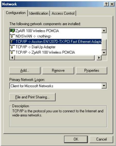
Installing Components
The Network window Configuration tab displays a list of installed components. You need a network adapter, the TCP/IP protocol and Client for Microsoft Networks.
If you need the adapter:
a. In the Network window, click Add.
b. Select Adapter and then click Add.
c. Select the manufacturer and model of your network adapter and then click OK.
If you need TCP/IP:
a. In the Network window, click Add.
b. Select Protocol and then click Add.
c. Select Microsoft from the list of manufacturers.
d. Select TCP/IP from the list of network protocols and then click OK.
If you need Client for Microsoft Networks:
a. Click Add.
b. Select Client and then click Add.
c. Select Microsoft from the list of manufacturers.
d. Select Client for Microsoft Networks from the list of network clients and then click OK.
e. Restart your computer so the changes you made take effect.
Configuring
- In the Network window Configuration tab, select your network adapter's TCP/IP entry and click Properties.
2. Click the IP Address tab.
-If your IP address is dynamic, select Obtain an IP address automatically.
-If you have a static IP address, select Specify an IP address and type your information into the IP Address and Subnet Mask fields.
3. Click the DNS Configuration tab.
-If you do not know your DNS information, select Disable DNS.
-If you know your DNS information, select Enable DNS and type the information in the fields below (you may not need to fill them all in).

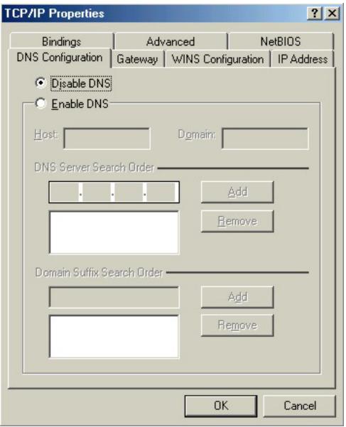
4. Click the Gateway tab.
-If you do not know your gateway's IP address, remove previously installed gateways.
-If you have a gateway IP address, type it in the New gateway field and click Add.
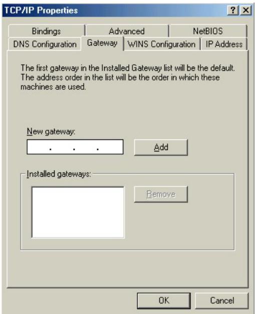
- Click OK to save and close the TCP/IP Properties window.
- Click OK to close the Network window. Insert the Windows CD if prompted.
- Turn on your Prestige and restart your computer when prompted.
Verifying Settings
-
Click Start and then Run.
-
In the Run window, type "winipcfg" and then click OK to open the IP Configuration window.
-
Select your network adapter. You should see your computer's IP address, subnet mask and default gateway.
Windows 2000/NT/XP
-
For Windows XP, click start, Control Panel. In Windows 2000/NT, click Start, Settings, Control Panel.
-
For Windows XP, click Network Connections. For Windows 2000/NT, click Network and Dial-up Connections.
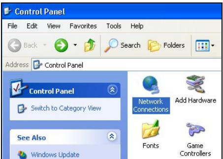
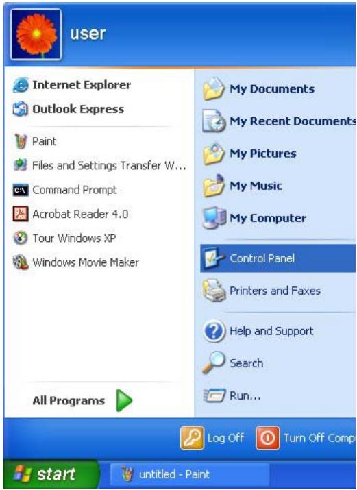
- Right-click Local Area Connection and then click Properties.
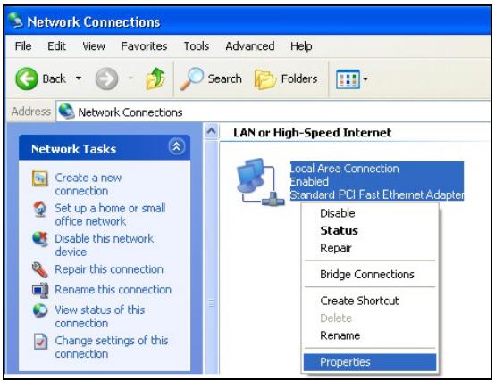
-
Select Internet Protocol (TCP/IP) (under the General tab in Win XP) and click Properties.
-
The Internet Protocol TCP/IP Properties window opens (the General tab in Windows XP).
-If you have a dynamic IP address click Obtain an IP address automatically. -If you have a static IP address click Use the following IP Address and fill in the IP address Subnet mask, and Default gateway fields.
Click Advanced.
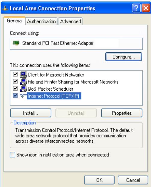
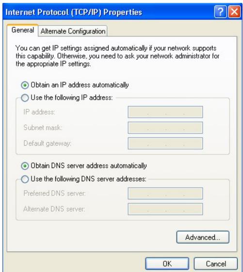
- -If you do not know your gateway's IP address, remove any previously installed gateways in the IP Settings tab and click OK.
Do one or more of the following if you want to configure additional IP addresses:
-In the IP Settings tab, in IP addresses, click Add.
-In TCP/IP Address, type an IP address in IP address and a subnet mask in Subnet mask, and then click Add.
-Repeat the above two steps for each IP address you want to add.
-Configure additional default gateways in the IP Settings tab by clicking Add in Default gateways.
-In TCP/IP Gateway Address, type the IP address of the default gateway in Gateway. To manually configure a default metric (the number of transmission hops), clear the Automatic metric check box and type a metric in Metric.
-Click Add.
-Repeat the previous three steps for each default gateway you want to add.
-Click OK when finished.
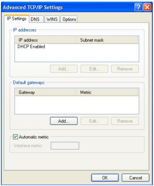
- In the Internet Protocol TCP/IP Properties window (the General tab in Windows XP):
-Click Obtain DNS server address automatically if you do not know your DNS server IP address(es).
-If you know your DNS server IP address(es), click Use the following DNS server addresses, and type them in the Preferred DNS server and Alternate DNS server fields.
If you have previously configured DNS servers, click Advanced and then the DNS tab to order them.

- Click OK to close the Internet Protocol (TCP/IP) Properties window.
- Click OK to close the Local Area Connection Properties window.
- Turn on your Prestige and restart your computer (if prompted).
Verifying Settings
- Click Start, All Programs, Accessories and then Command Prompt.
- In the Command Prompt window, type "ipconfig" and then press [ENTER]. You can also open Network Connections, right-click a network connection, click Status and then click the Support tab.
Macintosh OS 8/9
- Click the Apple menu, Control Panel and double-click TCP/IP to open the TCP/IP Control Panel.
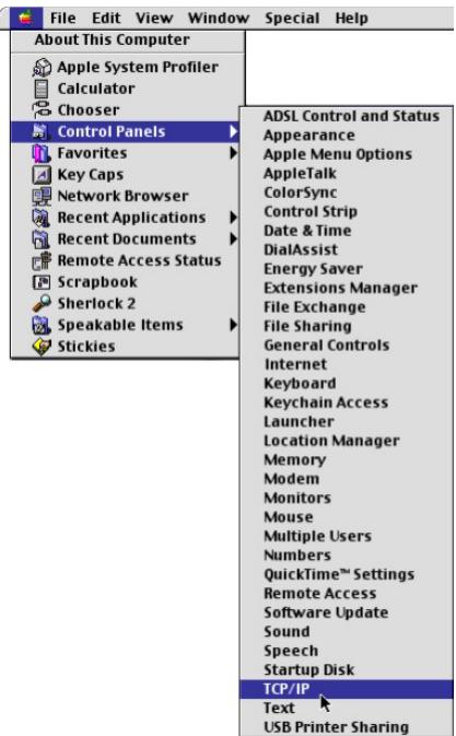
- Select Ethernet built-in from the Connect via list.
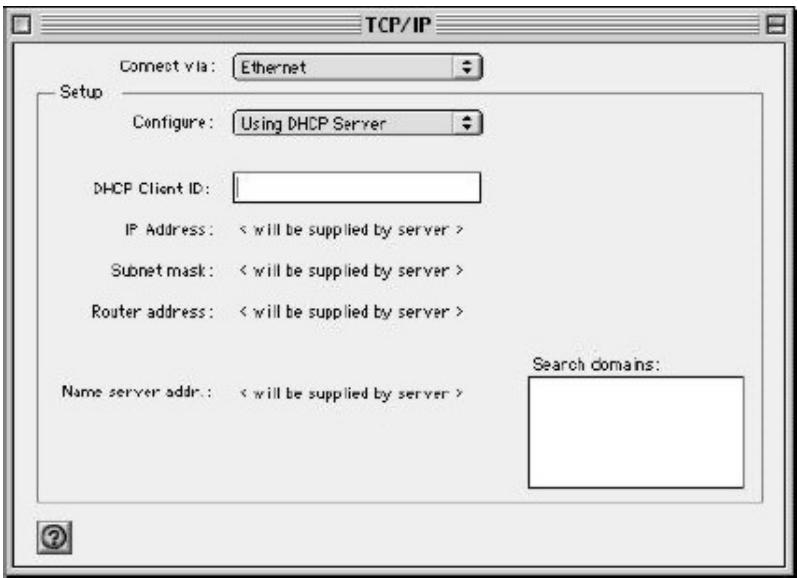
- For dynamically assigned settings, select Using DHCP Server from the Configure: list.
- For statically assigned settings, do the following:
-From the Configure box, select Manually.
-Type your IP address in the IP Address box.
-Type your subnet mask in the Subnet mask box.
-Type the IP address of your Prestige in the Router address box.
- Close the TCP/IP Control Panel.
- Click Save if prompted, to save changes to your configuration.
- Turn on your Prestige and restart your computer (if prompted).
Verifying Settings
Check your TCP/IP properties in the TCP/IP Control Panel window.
Macintosh OS X
- Click the Apple menu, and click System Preferences to open the System Preferences window.
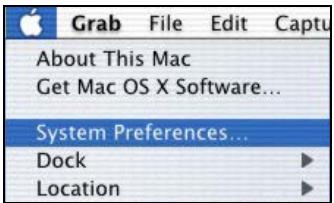
-
Click Network in the icon bar.
-
Select Automatic from the Location list.
- Select Built-in Ethernet from the Show list.
- Click the TCP/IP tab.
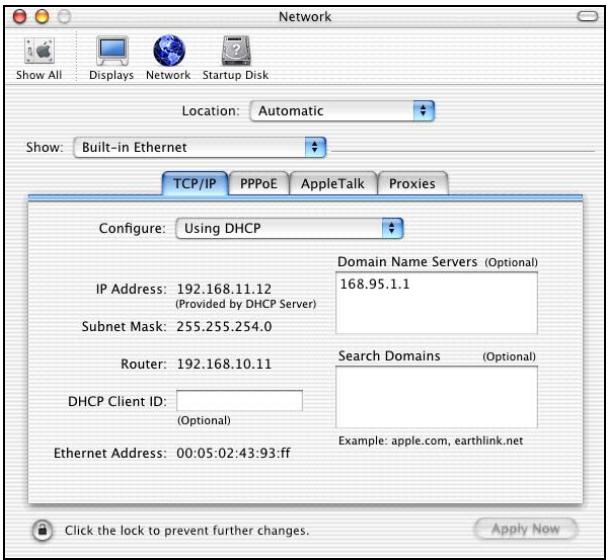
- For dynamically assigned settings, select Using DHCP from the Configure list.
- For statically assigned settings, do the following:
-From the Configure box, select Manually.
-Type your IP address in the IP Address box.
-Type your subnet mask in the Subnet mask box.
-Type the IP address of your Prestige in the Router address box.
- Click Apply Now and close the window.
- Turn on your Prestige and restart your computer (if prompted).
Verifying Settings
Check your TCP/IP properties in the Network window.
Appendix I
Splitters and Microfilters
This appendix tells you how to install a POTS splitter or a telephone microfilter.
Connecting a POTS Splitter
When you use the Full Rate (G.dmt) ADSL standard, you can use a POTS (Plain Old Telephone Service) splitter to separate the telephone and ADSL signals. This allows simultaneous Internet access and telephone service on the same line. A splitter also eliminates the destructive interference conditions caused by telephone sets.
Install the POTS splitter at the point where the telephone line enters your residence, as shown in the following figure.
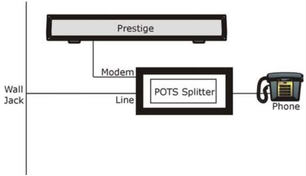
flowchart
graph TD
    A["Prestige"] --> B["Modem"]
    B --> C["POTS Splitter"]
    C --> D["Phone"]
    style A fill:#f9f,stroke:#333
    style B fill:#ccf,stroke:#333
    style C fill:#cfc,stroke:#333
    style D fill:#fcc,stroke:#333
Diagram I-1 Connecting a POTS Splitter
Step 1. Connect the side labeled “Phone” to your telephone.
Step 2. Connect the side labeled “Modem” to your Prestige.
Step 3. Connect the side labeled "Line" to the telephone wall jack.
Telephone Microfilters
Telephone voice transmissions take place in the lower frequency range, 0 - 4KHz, while ADSL transmissions take place in the higher bandwidth range, above 4KHz. A microfilter acts as a low-pass filter, for your telephone, to ensure that ADSL transmissions do not interfere with your telephone voice transmissions. The use of a telephone microfilter is optional.
Step 1. Connect a phone cable from the wall jack to the single jack end of the Y- Connector.
Step 2. Connect a cable from the double jack end of the Y-Connector to the “wall side” of the microfilter.
Step 3. Connect another cable from the double jack end of the Y-Connector to the Prestige.
Step 4. Connect the “phone side” of the microfilter to your telephone as shown in the following figure.
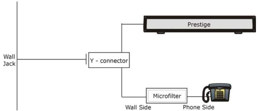
flowchart
graph TD
    A["Wall Jack"] --> B["Y - connector"]
    B --> C["Prestige"]
    B --> D["Microfilter"]
    D --> E["Phone Side"]
Diagram I-2 Connecting a Microfilter
Prestige With ISDN
This section relates to people who use their Prestige with ADSL over ISDN (digital telephone service) only. The following is an example installation for the Prestige with ISDN.
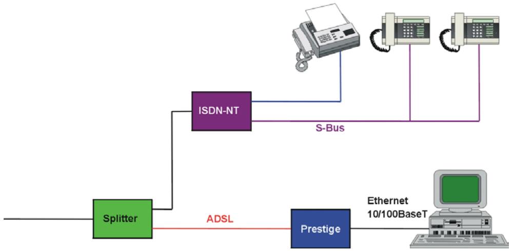
flowchart
graph LR
    A["Splitter"] -->|ADSL| B["ISDN-NT"]
    B -->|S-Bus| C["Ethernet 10/100BaseT"]
    B --> D["Prestige"]
    D -->|ADSL| A
Diagram I-3 Prestige with ISDN
Appendix J
Log Descriptions
This appendix provides descriptions of example log messages ^1 .
Chart J-1 System Maintenance Logs
| LOG MESSAGE | DESCRIPTION |
| Time calibration is successful | The router has adjusted its time based on information from the time server. |
| Time calibration failed | The router failed to get information from the time server. |
| DHCP client gets %s | A DHCP client got a new IP address from the DHCP server. |
| DHCP client IP expired | A DHCP client's IP address has expired. |
| DHCP server assigns %s | The DHCP server assigned an IP address to a client. |
| SMT Login Successfully | Someone has logged on to the router's SMT interface. |
| SMT Login Fail | Someone has failed to log on to the router's SMT interface. |
| WEB Login Successfully | Someone has logged on to the router's web configurator interface. |
| WEB Login Fail | Someone has failed to log on to the router's web configurator interface. |
| TELNET Login Successfully | Someone has logged on to the router via telnet. |
| TELNET Login Fail | Someone has failed to log on to the router via telnet. |
| FTP Login Successfully | Someone has logged on to the router via ftp. |
| FTP Login Fail | Someone has failed to log on to the router via ftp. |
Chart J-2 UPnP Logs
| LOG MESSAGE | DESCRIPTION |
| UPnP pass through Firewall | UPnP packets can pass through the firewall. |
For the content filtering logs “(Destination)” means the destination IP address or domain name.
Chart J-3 Content Filtering Logs
| MESSAGE | NOTE | DESCRIPTION |
| (Destination)Keyword Blocking | WebBlock | The Prestige blocked access to an address or domain name that had a forbidden keyword. |
| (Destination)Contains ActiveX | WebBlock | The Prestige blocked access to an IP address or domain name that contains ActiveX because the content filter is set to forbid ActiveX. |
| (Destination)Contains Java applet | WebBlock | The Prestige blocked access to an IP address or domain name that contains a Java applet because the content filter is set to forbid Java applets. |
| (Destination)Contains cookie | WebBlock | The Prestige blocked access to an IP address or domain name that contains a cookie because the content filter is set to forbid cookies. |
| (Destination)Proxy mode detected | WebBlock | The Prestige blocked access to an IP address or domain name that contains a proxy because the content filter is set to forbid proxies. |
| (Destination) | WebForward | The Prestige allowed access to an address or domain name when content filtering was turned off according to its schedule. |
The attack logs may include the protocol (Protocol) of the packet (for example TCP or UDP) that triggered the log.
Chart J-4 Attack Logs
| LOG MESSAGE | DESCRIPTION |
| attack (Protocol) | The firewall detected an attack. The log may also display the protocol (for example TCP or UDP). |
| land Protocol) | The firewall detected a land attack. The log may also display the protocol (for example TCP or UDP). |
| icmp echo ICMP (type:%d, code:%d) | The firewall detected an ICMP echo attack. See the section on ICMP messages for type and code details. |
| syn flood TCP | The firewall detected a TCP syn flood attack. |
| ports scan TCP | The firewall detected a TCP port scan attack. |
| teardrop (Protocol) | The firewall detected a teardrop attack. |
| illegal command TCP | The firewall detected a TCP SMTP illegal command attack. |
| NetBIOS TCP | The firewall detected a TCP NetBIOS attack. |
| ip spoofing - no routing entry (Protocol) | The firewall detected an IP spoofing attack while the Prestige did not have a default route. The log may also display the protocol (for example TCP or UDP). |
| vulnerability ICMP (type:%d, code:%d) | The firewall detected an ICMP vulnerability attack; see the section on ICMP messages for type and code details. |
| traceroute ICMP (type:%d, code:%d) | The firewall detected an ICMP traceroute attack; see the section on ICMP messages for type and code details. |
Access logs may include the following information:
➢ (Protocol) is the protocol of the packet (for example TCP or UDP) that triggered the log.
➢ (Direction) is the direction in which the packet was traveling (for example LAN to WAN or WAN to LAN)
➢ (Rule) is the number of the firewall rule which caused the log.
Chart J-5 Access Logs
| LOG MESSAGE | DESCRIPTION |
| Firewall default policy (Protocol, Direction) | Access matched the default policy and the Prestige blocked or forwarded it according to the configuration of the default firewall policy. |
| Firewall rule match (Protocol, Direction, Rule) | Access matched a firewall rule and the Prestige blocked or forwarded it according to the rule's configuration. |
| Firewall rule NOT match: (Protocol, Direction, Rule) | Access did not match a firewall rule and the Prestige logged it. |
| dest port (Protocol, Direction) | Access did not match a firewall rule's destination port and the Prestige logged it. |
| src port (Protocol, Direction) | Access did not match a firewall rule's source port and the Prestige logged it. |
| dest IP (Protocol, Direction) | Access did not match a firewall rule's destination IP address and the Prestige logged it. |
| src IP (Protocol, Direction) | Access did not match a firewall rule's source IP address and the Prestige logged it. |
| protocol (Protocol, Direction) | Access did not match a firewall rule's protocol and the Prestige logged it. |
| Triangle route packet forwarded (Protocol) | The firewall allowed a triangle route session to pass through. |
| ICMP Source Quench | The Prestige sent or received an ICMP source quench packet to tell a host to slow down data transmission. |
| ICMP Time Exceed | The Prestige sent or received an ICMP Time Exceed packet because a packet with zero Time To Live (TTL) was dropped. |
| ICMP Destination Unreachable | The Prestige sent or received an ICMP Destination Unreachable packet when a packet was dropped because the target port was not open. |
| Packet without a NAT table entry blocked (Protocol) | The router blocked a packet that did not have a corresponding NAT table entry. |
Chart J-5 Access Logs
| LOG MESSAGE | DESCRIPTION |
| Out of order TCP handshake packet blocked (Protocol) | The router blocked a TCP handshake packet that came out of the proper order |
| Unsupported/out-of-order ICMP (Protocol) | The Prestige generates this log after it drops an ICMP packet due to one of the following two reasons:1. The Prestige does not support the ICMP packet's protocol.2. The ICMP packet is an echo reply for which there was no corresponding echo request. |
| Router reply ICMP packet | The router sent an ICMP response packet. This packet automatically bypasses the firewall. |
| Remote access denied | The router blocked a remote access attempt. |
Chart J-6 TCP Reset Logs
| LOG MESSAGE | DESCRIPTION |
| Firewall sent TCP reset packets | The firewall sent out TCP reset packets. |
Chart J-7 ICMP Notes
| TYPE | CODE | DESCRIPTION |
| 0 | Echo Reply | |
| 0 | Echo reply message | |
| 3 | Destination Unreachable | |
| 0 | Net unreachable | |
| 1 | Host unreachable | |
| 2 | Protocol unreachable | |
| 3 | Port unreachable |
Chart J-7 ICMP Notes
| TYPE | CODE | DESCRIPTION |
| 4 | A packet that needed fragmentation was dropped because it was set to Don't Fragment (DF) | |
| 5 | Source route failed | |
| 4 | Source Quench | |
| 0 | A gateway may discard internet datagrams if it does not have the buffer space needed to queue the datagrams for output to the next network on the route to the destination network. | |
| 5 | Redirect | |
| 0 | Redirect datagrams for the Network | |
| 1 | Redirect datagrams for the Host | |
| 2 | Redirect datagrams for the Type of Service and Network | |
| 3 | Redirect datagrams for the Type of Service and Host | |
| 8 | Echo | |
| 0 | Echo message | |
| 11 | Time Exceeded | |
| 0 | Time to live exceeded in transit | |
| 1 | Fragment reassembly time exceeded | |
| 12 | Parameter Problem | |
| 0 | Pointer indicates the error | |
| 13 | Timestamp | |
| 0 | Timestamp request message | |
| 14 | Timestamp Reply | |
| 0 | Timestamp reply message | |
| 15 | Information Request | |
| 0 | Information request message | |
| 16 | Information Reply |
Chart J-7 ICMP Notes
| TYPE | CODE | DESCRIPTION |
| 0 | Information reply message |
VPN/IPSec logs
To view the IPSec and IKE connection log, type 3 in menu 27 and press [ENTER] to display the IPSec log as shown next. The following figure shows a typical log from the initiator of a VPN connection.
Index: Date/Time: Log:
001 01 Jan 08:02:22 Send Main Mode request to <192.168.100.101>
002 01 Jan 08:02:22 Send:<SA>
003 01 Jan 08:02:22 Recv:<SA>
004 01 Jan 08:02:24 Send:<KE><NONCE>
005 01 Jan 08:02:24 Recv:<KE><NONCE>
006 01 Jan 08:02:26 Send:<ID><HASH>
007 01 Jan 08:02:26 Recv:<ID><HASH>
008 01 Jan 08:02:26 Phase 1 IKE SA process done
009 01 Jan 08:02:26 Start Phase 2: Quick Mode
010 01 Jan 08:02:26 Send:<HASH><SA><NONCE><ID><ID>
011 01 Jan 08:02:26 Recv:<HASH><SA><NONCE><ID><ID>
012 01 Jan 08:02:26 Send:<HASH>
Clear IPSec Log (y/n):
Diagram J-1 Example VPN Initiator IPSec Log
VPN Responder IPSec Log
The following figure shows a typical log from the VPN connection peer.
Index: Date/Time: Log:
001 01 Jan 08:08:07 Recv Main Mode request from <192.168.100.100>
002 01 Jan 08:08:07 Recv:<SA>
003 01 Jan 08:08:08 Send:<SA>
004 01 Jan 08:08:08 Recv:<KE><NONCE>
005 01 Jan 08:08:10 Send:<KE><NONCE>
006 01 Jan 08:08:10 Recv:<ID><HASH>
007 01 Jan 08:08:10 Send:<ID><HASH>
008 01 Jan 08:08:10 Phase 1 IKE SA process done
009 01 Jan 08:08:10 Recv:<HASH><SA><NONCE><ID><ID>
010 01 Jan 08:08:10 Start Phase 2: Quick Mode
011 01 Jan 08:08:10 Send:<HASH><SA><NONCE><ID><ID>
012 01 Jan 08:08:10 Recv:<HASH>
Clear IPSec Log (y/n):
Diagram J-2 Example VPN Responder IPSec Log
This menu is useful for troubleshooting. A log index number, the date and time the log was created and a log message are displayed.
Double exclamation marks (!!) denote an error or warning message.
The following table shows sample log messages during IKE key exchange.
Chart J-8 Sample IKE Key Exchange Logs
| LOG MESSAGE | DESCRIPTION |
| Send <Symbol> Mode request to <IP> | The Prestige has started negotiation with the peer. |
| Send <Symbol> Mode request to <IP> | |
| Recv <Symbol> Mode request from <IP> | The Prestige has received an IKE negotiation request from the peer. |
| Recv <Symbol> Mode request from <IP> | |
| Recv:<Symbol> | IKE uses the ISAKMP protocol (refer to RFC2408 – ISAKMP) to transmit data. Each ISAKMP packet contains payloads of different types that show in the log – see Chart J-10. |
| Phase 1 IKE SA process done | Phase 1 negotiation is finished. |
Chart J-8 Sample IKE Key Exchange Logs
| LOG MESSAGE | DESCRIPTION |
| Start Phase 2: Quick Mode | Phase 2 negotiation is beginning using Quick Mode. |
| !! IKE Negotiation is in process | The Prestige has begun negotiation with the peer for the connection already, but the IKE key exchange has not finished yet. |
| !! Duplicate requests with the same cookie | The Prestige has received multiple requests from the same peer but it is still processing the first IKE packet from that peer. |
| !! No proposal chosen | The parameters configured for Phase 1 or Phase 2 negotiations don’t match. Please check all protocols and settings for these phases. For example, one party may be using 3DES encryption, but the other party is using DES encryption, so the connection will fail. |
| !! Verifying Local ID failed!! Verifying Remote ID failed | During IKE Phase 2 negotiation, both parties exchange policy details, including local and remote IP address ranges. If these ranges differ, then the connection fails. |
| !! Local / remote IPs of incoming request conflict with rule <#d> | If the security gateway is “0.0.0.0”, the Prestige will use the peer’s “Local Addr” as its “Remote Addr”. If this IP (range) conflicts with a previously configured rule then the connection is not allowed. |
| !! Invalid IP/ | The peer’s “Local IP Addr” range is invalid. |
| !! Remote IP/conflicts | If the security gateway is “0.0.0.0”, the Prestige will use the peer’s “Local Addr” as its “Remote Addr”. If a peer’s “Local Addr” range conflicts with other connections, then the Prestige will not accept VPN connection requests from this peer. |
| !! Active connection allowed exceeded | The Prestige limits the number of simultaneous Phase 2 SA negotiations. The IKE key exchange process fails if this limit is exceeded. |
| !! IKE Packet Retransmit | The Prestige did not receive a response from the peer and so retransmits the last packet sent. |
| !! Failed to send IKE Packet | The Prestige cannot send IKE packets due to a network error. |
Chart J-8 Sample IKE Key Exchange Logs
| LOG MESSAGE | DESCRIPTION |
| !! Too many errors! Deleting SA | The Prestige deletes an SA when too many errors occur. |
| !! ID type mismatch | The ID type of an incoming packet does not match the local's peer ID type. |
| !! ID content mismatch | The ID content of an incoming packet does not match the local's peer ID content. |
| !! No known phase 1 ID type found | The ID type of an incoming packet does not match any known ID type. |
| vs. My Remote | The IP address type or IP address of an incoming packet does not match the peer IP address type or IP address configured on the local router. The log displays this router's configured remote IP address type or IP address that the incoming packet did not match. |
| vs. My Local | The IP address type or IP address of an incoming packet does not match the peer IP address type or IP address configured on the local router. The log displays this router's configured local IP address type or IP address that the incoming packet did not match. |
| -> | The router sent a payload type of IKE packet. |
The following table shows sample log messages during packet transmission.
Chart J-9 Sample IPSec Logs During Packet Transmission
| LOG MESSAGE | DESCRIPTION |
| !! WAN IP changed to | If the Prestige's WAN IP changes, all configured “My IP Addr” are changed to b “0.0.0.0”. If this field is configured as 0.0.0.0, then the Prestige will use the current Prestige WAN IP address (static or dynamic) to set up the VPN tunnel. |
| !! Cannot find outbound SA for rule <%d> | The packet matches the rule index number (#d), but Phase 1 or Phase 2 negotiation for outbound (from the VPN initiator) traffic is not finished yet. |
Chart J-9 Sample IPSec Logs During Packet Transmission
| LOG MESSAGE | DESCRIPTION |
| !! Discard REPLAY packet | If the Prestige receives a packet with the wrong sequence number it will discard it. |
| !! Inbound packet authentication failed | The authentication configuration settings are incorrect. Please check them. |
| !! Inbound packet decryption failed | The decryption configuration settings are incorrect. Please check them. |
| Rule <#d> idle time out, disconnect | If an SA has no packets transmitted for a period of time (configurable via CI command), the Prestige drops the connection. |
The following table shows RFC-2408 ISAKMP payload types that the log displays. Please refer to the RFC for detailed information on each type.
Chart J-10 RFC-2408 ISAKMP Payload Types
| LOG DISPLAY | PAYLOAD TYPE |
| SA | Security Association |
| PROP | Proposal |
| TRANS | Transform |
| KE | Key Exchange |
| ID | Identification |
| CER | Certificate |
| CER_REQ | Certificate Request |
| HASH | Hash |
| SIG | Signature |
| NONCE | Nonce |
| NOTFY | Notification |
| DEL | Delete |
| VID | Vendor ID |
Appendix K Index
A
Action for Matched Packets.... 13-11
Active....24-8, 24-11
Address Assignment 5-2
Ad-hoc Configuration C-2
ADSL, what is it?...... xxviii
Allocated Budget 24-9
Alternative Subnet Mask Notation...... B-3
Application-level Firewalls.... 11-1
AT command 24-5, 24-6, 37-1
Attack Alert....12-2, 12-3, 12-4
Attack Types 11-6
Authen....24-9
Authentication....24-9, 28-4, 28-5
auto-negotiation 1-3
B
Backup 37-2
Basic Service Set.... C-2
Blocking Time 12-3
Bridging 25-2
Ether Address 30-4
Ethernet....30-1
Ethernet Addr Timeout 30-3
Remote Node 30-1
Static Route Setup.... 30-3
Brute-force Attack, 11-6
BSS ...... See Basic Service Set
Budget Management 38-2, 38-3
C
call back delay....24-7
Call Filtering 33-1
Call Filters
Built-In....33-1
User-Defined 33-1
Call Scheduling.... 41-1
Maximum Number of Schedule Sets ...... 41-1
PPPoE 41-3
Precedence.... 41-1
Precedence Example...... See precedence
CDR 36-7
CDR (Call Detail Record).... 36-6
Channel ID 26-2
CHAP 24-9, 28-4
Classes of IP Addresses....B-1
Collision 36-3
Command Interpreter Mode.... 38-1
Community 34-2
Computer Name 23-1
Conditions that prevent TFTP and FTP from working over WAN 37-4
Configuration.... 3-11, 21-6
Content Filtering.... 15-1
Categories.... 15-1
Exempt Computers 15-4
Keywords 15-1, 15-3
Copyright......ii
Cost Of Transmission 28-7, 29-3
Country Code.... 36-4
CPU Load 36-3
Custom Ports
Creating/Editing 14-2
Introduction 14-1
Customer Support......v
Customized Services.... 14-2
D
Data encryption.... 6-4
Data Filtering 33-1
Default Policy Log.... 13-5
Denial of Service ..... 11-2, 11-3, 12-2, 12-3, 32-1
Destination Address.... 13-3, 13-11
Device Filter rules.... 33-15
DHCP 1-4,3-11,5-2,9-1,21-6,36-4
Diagnostic Tools 36-1
dial timeout.... 24-7
Digital Subscriber Line Access Multiplexer.... 1-6
Direct Sequence Spread Spectrum......C-1
Distribution System ......C-2
DNS 25-3
Domain Name 5-2, 8-7
Domain Name System 5-1
DoS Basics 11-3
Types 11-4
DoS (Denial of Service).... 1-2
drop timeout.... 24-7
DS ...... See Distribution System
DSL (Digital Subscriber Line)...... xxviii
DSL, What Is It? ...... xxviii
DSLAM ......See Digital Subscriber Line Access Multiplexer
DSSS......See Direct Sequence Spread Spectrum
DTR 7-17,24-7
Dynamic DNS....1-3, 9-1, 23-2
DYNDNS Wildcard.... 9-1
E
EAP....6-8
EAP Authentication Sequence 6-9
ECHO 8-7
Edit IP 24-9
E-mail Log Example 20-6
Encapsulation....1-5, 3-1, 27-5, 28-2
ENET ENCAP.... 3-1
PPP over Ethernet.... 3-1
PPPoA 3-1
RFC 1483 3-2
Error Log 36-5
Error/Information Messages Sample 36-6
ESS ...... See Extended Service Set
ESS ID 6-1
Ethernet Encapsulation 8-6
Ethernet Traffic 33-19
Example Internal SPTGEN Screens ......G-1
Extended Service Set...... C-2
F
Factory LAN Defaults 5-2
FCC ....iii
FHSS .. See Frequency-Hopping Spread Spectrum
Filename Conventions....37-1
Filter 24-15, 25-1
Applying Filters ....33-18
Ethernet traffic 33-19
Ethernet Traffic 33-19
Filter Rules....33-7
Filter Structure 33-4
Generic Filter Rule....33-13
Remote Node....28-8
Remote Node Filter 28-9
Remote Node Filters 33-19
Sample....33-17
SUA....33-15
TCP/IP Filter Rule....33-9
Filter Log.... 36-7, 36-8
Filter Rule....33-10
Filter Rule Process....33-3
Filter Rule Setup....33-8
Filter Rules Summary Sample....33-18
Filter Set Class....33-9
Filter Set Configuration.... 33-4, 33-6
Filtering 33-1, 33-9
Filtering Process Outgoing Packets ....33-2
Finger 8-7
Firewall Access Methods ....32-1
Address Type 13-12
Alerts....12-2
Connection Direction 13-3
Creating/Editing Rules 13-9
Custom Ports......See Custom Ports
Enabling 12-1
Firewall Vs Filters....11-12
Guidelines For Enhancing Security ..... 11-11
Introduction 11-2
LAN to WAN Rules 13-3
Logs 13-4
Policies....13-1
Remote Management 12-1, 32-1
Rule Checklist.... 13-1
Rule Logic 13-1
Rule Precedence.... 13-4
Rule Security Ramifications 13-2
Services.... 13-6
SMT Menus 32-1
Types 11-1
When To Use 11-13
Firmware File
Maintenance 21-11
Fragment Threshold 26-2
Fragmentation Threshold 6-3
Frame Relay 1-6
Frequency-Hopping Spread Spectrum ...... C-1
FTP....8-6, 8-7, 9-1, 18-1, 39-2
Restrictions 39-2
FTP File Transfer 37-10
FTP Restrictions....18-1, 37-4
FTP Server 31-15
Full Rate....I-1
G
Gateway 29-3
Gateway Node 30-4
General Setup....23-1
H
Half-Open Sessions.... 12-2
Hidden Menus 22-4
Hop Count....28-7, 29-3
Host 4-2
Host IDs ...... B-1
HTTP 8-7, 11-1, 11-3, 11-4, 42-9, 42-10
HyperTerminal program 37-6, 37-9
I
IANA 3-5
IBSS......See Independent Basic Service Set
ICMP echo.... 11-6
Idle Timeout 24-10
IEEE 802.11.....C-1
IEEE 802.11b....1-2
IGMP 5-3
IGMP support 28-7
Independent Basic Service Set......C-2
Infrastructure Configuration ......C-2
Install UPnP 19-3
Windows Me 19-3
Windows XP.... 19-4
Interactive Applications.... 40-1
Internal SPTGEN.... 44-1
FTP Download Example 44-3
FTP Upload Example 44-4
Points to Remember 44-2
Text File 44-1
Internal SPTGEN Screens ......G-1
Internet access.... 27-1
Internet Access...... 1-1, 1-6, 1-7, 25-2, 27-1, 27-5
Internet Access Setup ...... A-3, 31-1
Internet Assigned Numbers Authority .. See IANA
Internet Control Message Protocol (ICMP)... 11-6
IP address.... 24-9, 24-11
IP Address3-4, 5-3, 8-6, 8-9, 21-6, 25-3, 29-3, 30-4, 33-10, 36-4, 36-9, 40-3
Remote 24-11
IP Address Assignment.... 3-4
ENET ENCAP 3-5
PPPoA or PPPoE 3-5
RFC 1483 3-5
IP Addressing ......B-1
IP Alias Setup 27-2
IP Classes......B-1
IP Filter 33-12
Logic Flow 33-11
IP mask 33-10
IP Packet 33-13
IP Policies 40-5
IP Policy Routing (IPPR).... 1-4, 27-1
Applying an IP Policy 40-5
Ethernet IP Policies 40-5
Gateway.... 40-5
IP Pool Setup 3-12
IP Ports 42-9, 42-10
IP Protocol 40-4
IP Routing Policy (IPPR).... 40-1
Benefits.... 40-1
Cost Savings 40-1
Criteria.... 40-1
Load Sharing 40-1
Setup 40-2
IP Routing Policy Setup.... 40-3
IP Spoofing.... 11-4, 11-7
IP Static Route 29-1
IP Static Route Setup 29-2
IP Subnet Mask....24-12
Remote 24-12
IPSec standard 1-1
ISDN....I-2
K
Key Fields For Configuring Rules.... 13-2
L
LAN 36-3
LAN Setup....5-1, 7-1
LAN TCP/IP 5-2
LAN to WAN Rules 13-3
LAND 11-4, 11-6
Link type.... 36-2
LLC-based Multiplexing.... 28-10
Local Network
Rule Summary 13-4
Log and Trace 36-6
Log Descriptions....J-1
Log Facility 36-7
Logging Option.... 33-11, 33-14
Login.... 28-4
Logs 20-1
M
MAC address 30-4
MAC Address Filter 26-3
MAC Address Filter Action.... 6-8, 26-4
MAC Address Filtering 6-6
Main Menu 22-5
Management Information Base (MIB) ......34-2
Max-incomplete High....12-3
Max-incomplete Low 12-3
MBS ......See Maximum Burst Size
Media Access Control 30-1
Message Logging 36-5
Metric 7-1, 24-12, 28-7, 29-3
Multicast....5-3, 24-12, 28-7
Multiplexing
LLC-based....3-2
VC-based....3-2
Multiplexing 1-5, 3-2, 27-6, 28-2
Multiprotocol Encapsulation 3-2
My Login....24-8
My Password 24-8
My WAN Address 24-12, 28-7
N
Nailed-Up Connection.... 3-6, 24-10
NAT....3-4, 8-6, 8-8, 24-12, 33-15
Application....8-3
Applying NAT in the SMT Menus......31-1
Configuring 31-3
Definitions....8-1
Examples....31-11
How NAT Works 8-2
Mapping Types 8-4
Non NAT Friendly Application Programs31-17
Ordering Rules 31-6
Server Sets....8-6
What NAT does....8-2
NAT Traversal....19-1
NetBIOS commands....11-6
Network Address Translation....27-7
Network Address Translation (NAT) 31-1
Network Management 1-5, 8-7
NNTP 8-7
O
One-Minute High 12-3
P
Packet
Error.... 36-2
Received 36-3
Transmitted 36-3
Packet Filtering 11-12
Packet Filtering Firewalls 11-1
Packet Triggered 36-7
Packets 36-2
PAP 24-9, 28-4
Password 4-1, 22-1, 22-6, 28-4, 34-2
Period(hr) 24-9
Ping 36-9
Ping of Death 11-4
Point-to-Point.... xxviii
Point-to-Point Tunneling Protocol 8-7
policy-based routing...... 40-1
POP3 8-7, 11-3, 11-4
Port Configuration.... 14-3
Port Numbers 8-7
PPP 24-10
PPP Encapsulation 28-10
PPP Log 36-7, 36-8
PPPoA 28-2
PPTP 8-7
Precedence 40-1, 40-4
Prestige Firewall Application.... 11-3
Private 24-12, 28-7, 29-4
Protocol 33-10
Protocol Filter Rules 33-15
Q
Quality of Service 40-1
Quick Start Guide 2-1
R
RADIUS....6-8
Shared Secret Key....6-9
RADIUS Message Types 6-9
RAS....36-4, 40-2
Rate
Receiving 36-2
Transmission....36-2
Read Me First.... xxvi
Related Documentation.... xxvi
Rem IP Address 24-11
Rem Node Name....24-8, 24-11
Remote DHCP Server 25-3
Remote Management
Firewall....12-1, 32-1
Remote Management and NAT 18-2
Remote Management Limitations...... 18-1, 39-2
Remote Management Setup 39-1
Remote Node 28-1, 36-2
Remote Node Profile 28-3
Remote Node Setup.... 28-1, 28-2
Remote Node Filter 24-14
Remote Node Index Number 36-2
Remote Node Traffic 33-20
Required fields 22-4
Restore Configuration.... 37-7
retry count.... 24-7
retry interval 24-7
RF signals C-1
RFC-1483 28-2
RFC-2364 28-2, 28-3
RIP ....24-12, 25-3, 28-7. See Routing Information Protocol
Routing Information Protocol 5-3
Direction 5-3
Version 5-3
Routing Policy 40-1
RTS Threshold....6-2, 26-2
Rule Summary 13-4, 14-6
Rules 13-1, 13-3
Checklist.... 13-1
Creating Custom.... 13-1
Key Fields 13-2
LAN to WAN 13-3
Logic.... 13-1
Predefined Services 13-6
Source and Destination Addresses ..... 13-11
Summary 13-4
Timeout 13-12
S
SA Monitor 43-1
Sample IP Addresses 28-8
Saving the State 11-7
Schedule Sets Duration.... 41-2
SCR......See Sustain Cell Rate
script 24-13
Security Association 43-1
Security In General 11-11
Security Ramifications.... 13-2
Server. ^8-5 , 10-2, 31-4, 31-5, 31-8, 31-9, 31-10, 31-13, 31-14, 38-5
Service iv, 13-2
Service Type....A-3, 14-3
Services....8-6, 8-7
setup a schedule 41-2
SMT Menu Overview 22-2
SMTP 8-7
SMTP Error Messages.... 20-5
Smurf 11-6
SNMP 8-7
Community 34-3
Configuration.... 34-2
Get 34-2
Manager.... 34-2
MIBs.... 34-2
Trap 34-2
Trusted Host 34-3
Source & Destination Addresses .... 13-11
Source Address 13-3, 13-10
Source-Based Routing 40-1
Splitters....I-1
SPTGEN Screens....G-1
Stateful Inspection ..... 1-2, 11-1, 11-2, 11-7, 11-8
Prestige 11-9
Process.... 11-8
Static Route Setup.... 29-1
Static Routing Topology.... 29-1
SUA 1-7, 8-6, 8-7
SUA (Single User Account) .. See NAT. See NAT
Subnet Mask ... 3-4, 5-3, 13-12, 24-12, 25-3, 28-6, 29-3, 36-4
Subnet Masks B-2
Subnetting......B-2
Supporting Disk....xxvi
SYN Flood.... 11-4, 11-5
SYN-ACK 11-5
Syntax Conventions.... xxvii
Syslog.... 14-3, 36-6
Syslog IP Address 36-7
Syslog Server....36-6
System Console Port Speed .... 36-5
Diagnostic 36-8
Log and Trace ....36-5
Syslog and Accounting 36-6
System Information....36-3
System Status 36-1
System Information 36-3
System Information & Diagnosis ....36-1
System Maintenance.20-4, 36-1, 36-3, 37-2, 37-5, 37-13, 37-14, 38-1, 38-2, 38-4, 38-5
System Management Terminal....22-3
System Parameter Table Generator ....44-1
System Status 36-2
System Timeout.... 18-2, 39-3
T
TCP Maximum Incomplete 12-3
TCP Security 11-10
TCP/IP...... 11-3, 11-4, 18-2, 24-11, 33-15, 36-9
Teardrop 11-4
Telephone Microfilters ...... I-1
Telnet....18-2
Telnet Configuration 18-2
Text File Format....44-1
TFTP And FTP Over WAN}....39-2 Restrictions....39-2
TFTP and FTP over WAN Will Not Work When....37-4
TFTP and FTP Over WAN}....18-1
TFTP File Transfer 37-12
TFTP Restrictions.... 18-1, 37-4
Three-Way Handshake.... 11-5
Threshold Values 12-2
Time and Date Setting....38-4, 38-5
Time Zone....38-5
Timeout....13-12, 13-13, 24-10
TOS (Type of Service) 40-1
Trace Records 36-5
Traceroute 11-7
Traffic Redirect....7-7, 7-8, 7-9
Setup 24-3
Transmission Rates 1-1
Type of Service....40-1, 40-3, 40-4, 40-5
U
UDP/ICMP Security 11-10
Universal Plug and Play 19-1
Application 19-1
Security issues 19-1
Universal Plug and Play Forum 19-2
UNIX Syslog....36-5, 36-7
UNIX syslog parameters 36-6
Upload Firmware 37-10
UPnP .... See Universal Plug and Play
Upper Layer Protocols 11-10
User Name 9-2
User Profiles....6-12, 35-5
V
VC-based Multiplexing 28-2
Virtual Private Network.... 1-1
VPI & VCI 3-2
W
WAN Setup.... 24-2
WAN to LAN Rules 13-3
Web Configurator2-1, 2-2, 2-3, 11-2, 11-11, 13-2, 32-2
WEP....6-4
WEP Encryption 26-3
Wireless LAN....C-1, 26-1
Benefits....C-1
Wireless LAN Setup 26-1
Wizard Setup 3-1
WLAN ...... See Wireless LAN
X
XMODEM protocol.... 37-2
Z
ZyNOS....37-1, 37-2
ZyNOS F/W Version 37-1
ZyXEL Limited Warranty
Note ......iv
ZyXEL's Firewall
Introduction 11-2
- Prestige 652 Series
- User's Guide
- Copyright
- Disclaimer
- Trademarks
- Federal Communications Commission (FCC) Interference Statement
- Notice 1
- Certifications
- ZyXEL Limited Warranty
- Note
- Safety Warnings
- Customer Support
- Table of Contents
- Chapter 5 LAN Setup ....5-1
- Chapter 6 Wireless LAN Setup....6-1
- Chapter 7 WAN Setup ....7-1
- NAT, Dynamic DNS and Time Zone...... III
- Chapter 8 Network Address Translation (NAT) Screens....8-1
- Chapter 9 Dynamic DNS Setup 9-1
- Chapter 10 Time Zone....10-1
- Firewall and Content Filters......IV
- Chapter 11 Firewalls.... 11-1
- Chapter 12 Firewall Configuration....12-1
- Chapter 13 Creating Custom Rules ....13-1
- Chapter 14 Customized Services....14-1
- Chapter 15 Content Filtering Screens....15-1
- VPN/IPSec V
- Chapter 16 Introduction to IPSec....16-1
- Chapter 17 VPN Screens ....17-1
- Remote Management, UPnP and Logs...... VI
- Chapter 18 Remote Management Configuration....18-1
- Chapter 19 Universal Plug-and-Play (UPnP)....19-1
- Chapter 20 Logs Screens ....20-1
- Maintenance......VII
- Chapter 21 Maintenance ....21-1
- SMT General Configuration......VIII
- Chapter 22 Introducing the SMT ...... 22-1
- Chapter 23 Menu 1 General Setup....23-1
- Chapter 24 Menu 2 WAN Backup Setup ....24-1
- Chapter 25 Menu 3 LAN Setup ....25-1
- Chapter 26 Wireless LAN Setup....26-1
- Chapter 27 Internet Access ...... 27-1
- Chapter 28 Remote Node Configuration ....28-1
- Chapter 29 Static Route Setup....29-1
- Chapter 30 Bridging Setup....30-1
- Chapter 31 Network Address Translation (NAT)....31-1
- Chapter 32 Enabling the Firewall....32-1
- SMT Advanced Management.... IX
- Chapter 33 Filter Configuration....33-1
- Chapter 34 SNMP Configuration ....34-1
- Chapter 35 System Security ....35-1
- Chapter 36 System Information and Diagnosis....36-1
- Chapter 37 Firmware and Configuration File Maintenance ....37-1
- Chapter 38 System Maintenance....38-1
- Chapter 39 Remote Management....39-1
- Chapter 40 IP Policy Routing ....40-1
- Chapter 41 Call Scheduling ....41-1
- SMT VPN/IPSec and Internal SPTGEN......X
- Chapter 42 VPN/IPSec Setup....42-1
- Chapter 43 SA Monitor ....43-1
- Chapter 44 Internal SPTGEN ....44-1
- Appendices and Index ......XI
- Appendix A Troubleshooting......A-1
- Appendix B IP Subnetting......B-1
- List of Figures
- List of Tables
- List of Charts
- Preface
- Don't forget to register your Prestige online at www.zyxel.com for free future product updates and information.
- About This User's Guide
- Use the web configurator, System Management Terminal (SMT) or command interpreter interface to configure your Prestige. Not all features can be configured through all interfaces.
- Related Documentation
- User Guide Feedback
- Syntax Conventions
- What is DSL?
- What is ADSL?
- Part I:
- Getting Started
- Chapter 1
- Getting To Know Your Prestige
- Introducing the Prestige 652 Series
- Features of the Prestige
- ● High Speed Internet Access
- - IPSec VPN Capability
- - Firewall
- - Content Filtering
- - IEEE 802.11b 11 Mbps Wireless LAN
- ● Wireless LAN MAC Address Filtering
- - Traffic Redirect
- - Auxiliary Port
- ● Universal Plug and Play (UPnP)
- - PPPoE Support (RFC2516)
- ● Network Address Translation (NAT)
- ● 10/100M Auto-negotiating Ethernet/Fast Ethernet Interface(s)
- ● Auto-crossover 10/100 Mbps Ethernet Interface(s)
- ● LAN/DMZ Interface
- ● Dynamic DNS Support
- ● Multiple PVC (Permanent Virtual Circuits) Support
- - ADSL Transmission Rate Standards
- - Protocol Support
- ● Networking Compatibility
- - Multiplexing
- - Encapsulation
- Network Management
- - Other PPPoE Features
- • Diagnostics Capabilities
- - Packet Filters
- - Ease of Installation
- - Housing
- Applications for the Prestige
- Internet Access
- Internet Single User Account
- Firewall for Secure Broadband Internet Access
- VPN Application
- LAN to LAN Application
- Chapter 2
- Introducing the Web Configurator
- Web Configurator Overview
- Accessing the Prestige Web Configurator
- Navigating the Prestige Web Configurator
- Resetting the Prestige
- Using The Reset Button
- Uploading a Configuration File Via Console Port
- Chapter 3
- Wizard Setup
- Wizard Setup Introduction
- Encapsulation
- ENET ENCAP
- PPP over Ethernet
- PPPoA
- RFC 1483
- Multiplexing
- VC-based Multiplexing
- LLC-based Multiplexing
- VPI and VCI
- Wizard Setup Configuration: First Screen
- IP Address and Subnet Mask
- IP Address Assignment
- IP Assignment with PPPoA or PPPoE Encapsulation
- IP Assignment with RFC 1483 Encapsulation
- IP Assignment with ENET ENCAP Encapsulation
- Private IP Addresses
- Nailed-Up Connection (PPP)
- NAT
- Wizard Setup Configuration: Second Screen
- DHCP Setup
- IP Pool Setup
- Wizard Setup Configuration: Third Screen
- Wizard Setup Configuration: Connection Tests
- Test Your Internet Connection
- Part II:
- Password, LAN, Wireless LAN and WAN
- Chapter 4
- Password Setup
- Password Overview
- Configuring Password
- Chapter 5
- LAN Setup
- LAN Overview
- LANs, WANs and the Prestige
- DNS Server Address
- DNS Server Address Assignment
- LAN TCP/IP
- Factory LAN Defaults
- IP Address and Subnet Mask
- RIP Setup
- Multicast
- Configuring LAN
- Chapter 6
- Wireless LAN Setup
- Wireless LAN Overview
- The WLAN screens are only available when a WLAN card is installed.
- Additional Installation Requirements for Using 802.1x
- Channel
- ESS ID
- RTS/CTS
- Enabling the RTS Threshold causes redundant network overhead that could negatively affect the throughput performance instead of providing a remedy.
- Fragmentation Threshold
- Levels of Security
- Data Encryption with WEP
- Inserting a PCMCIA Wireless LAN Card
- Configuring Wireless LAN
- Configuring MAC Filter
- Network Authentication
- EAP
- RADIUS
- - Accounting
- Types of RADIUS Messages
- EAP Authentication Overview
- Configuring 802.1x
- Configuring Local User Authentication
- Configuring RADIUS
- Chapter 7
- WAN Setup
- WAN Overview
- Metric
- PPPoE Encapsulation
- Traffic Shaping
- Configuring WAN Setup
- WAN Backup
- Traffic Redirect on the LAN
- Traffic Redirect on the WAN
- Configuring WAN Backup
- Configuring Advanced WAN Backup
- WAN - WAN Backup Setup- WAN Backup Advanced
- Basic
- TCP/IP Options
- PPP Options
- Connection
- Budget
- AT Command Strings
- DTR Signal
- Response Strings
- Configuring Advanced Modem Setup
- Part III:
- NAT, Dynamic DNS and Time Zone
- Chapter 8
- Network Address Translation (NAT)
- Screens
- NAT Overview
- NAT Definitions
- What NAT Does
- How NAT Works
- NAT Application
- NAT Mapping Types
- Port numbers do not change for One-to-One and Many-to-Many No Overload NAT mapping types.
- SUA (Single User Account) Versus NAT
- SUA Server
- Default Server IP Address
- Port Forwarding: Services and Port Numbers
- Configuring Servers Behind SUA (Example)
- Selecting the NAT Mode
- Configuring SUA Server
- Configuring Address Mapping
- Editing an Address Mapping Rule
- Chapter 9
- Dynamic DNS Setup
- Dynamic DNS
- DYNDNS Wildcard
- Configuring Dynamic DNS
- Chapter 10 Time Zone
- Configuring Time Zone
- Part IV:
- Firewall and Content Filters
- Chapter 11 Firewalls
- Firewall Overview
- Types of Firewalls
- Packet Filtering Firewalls
- Application-level Firewalls
- Stateful Inspection Firewalls
- Introduction to ZyXEL's Firewall
- Denial of Service
- Basics
- Types of DoS Attacks
- ☐ ICMP Vulnerability
- ☐ Illegal Commands (NetBIOS and SMTP)
- Traceroute
- Stateful Inspection
- Stateful Inspection Process
- Stateful Inspection and the Prestige
- The ability to define firewall rules is a very powerful tool. Using custom rules, it is possible to disable all firewall protection or block all access to the Internet. Use extreme caution when creating or deleting firewall rules. Test changes after creating them to make sure they work correctly.
- TCP Security
- UDP/ICMP Security
- Upper Layer Protocols
- Guidelines For Enhancing Security With Your Firewall
- Security In General
- Packet Filtering Vs Firewall
- Packet Filtering:
- When To Use Filtering
- Firewall
- When To Use The Firewall
- Chapter 12
- Firewall Configuration
- Remote Management and the Firewall
- Enabling the Firewall
- Firewall · Configuration · Config
- □ Firewall Enabled
- Attack Alert
- Alerts
- Threshold Values
- Half-Open Sessions
- TCP Maximum Incomplete and Blocking Time
- Chapter 13
- Creating Custom Rules
- Rules Overview
- Rule Logic Overview
- Rule Checklist
- Security Ramifications
- Key Fields For Configuring Rules
- Action
- Service
- Source Address
- Destination Address
- Connection Direction
- LAN to WAN Rules
- WAN to LAN Rules
- Logs
- Rule Summary
- Firewall · LAN to WAN · Rule Summary
- Predefined Services
- Creating/Editing Firewall Rules
- Source and Destination Addresses
- Timeout
- Factors Influencing Choices for Timeout Values
- Chapter 14
- Customized Services
- Introduction to Customized Services
- Creating/Editing A Customized Service
- Example Custom Service Firewall Rule
- Chapter 15
- Content Filtering Screens
- Content Filtering Overview
- Configuring Keyword Blocking
- Configuring the Schedule
- Configuring Trusted Computers
- Part V:
- VPN/IPSec
- Chapter 16
- Introduction to IPSec
- VPN Overview
- IPSec
- Security Association
- Other Terminology
- Encryption
- Data Confidentiality
- Data Integrity
- Data Origin Authentication
- VPN Applications
- - Linking Two or More Private Networks Together
- - Accessing Network Resources When NAT Is Enabled
- ▶ Unsupported IP Applications
- IPSec Architecture
- IPSec Algorithms
- Key Management
- Encapsulation
- Transport Mode
- Tunnel Mode
- IPSec and NAT
- Chapter 17
- VPN Screens
- VPN/IPSec Overview
- IPSec Algorithms
- AH (Authentication Header) Protocol
- ESP (Encapsulating Security Payload) Protocol
- My IP Address
- Secure Gateway Address
- Dynamic Secure Gateway Address
- VPN Summary Screen
- Keep Alive
- ID Type and Content
- ID Type and Content Examples
- Pre-Shared Key
- Editing VPN Policies
- IKE Phases
- Negotiation Mode
- Diffie-Hellman (DH) Key Groups
- Perfect Forward Secrecy (PFS)
- Configuring Advanced IKE Settings
- Manual Key Setup
- Security Parameter Index (SPI)
- 17.13Configuring Manual Key
- 17.14Viewing SA Monitor
- 17.15Configuring Global Setting
- Telecommuter VPN/IPSec Examples
- Telecommuters Sharing One VPN Rule Example
- Telecommuters Using Unique VPN Rules Example
- 17.17VPN and Remote Management
- Part VI:
- Remote Management, UPnP and Logs
- Chapter 18
- Remote Management Configuration
- Remote Management Overview
- Remote Management Limitations
- Remote Management and NAT
- System Timeout
- Telnet
- FTP
- Web
- Configuring Remote Management
- Chapter 19
- Universal Plug-and-Play (UPnP)
- Introducing Universal Plug and Play
- How do I know if I'm using UPnP?
- NAT Traversal
- Cautions with UPnP
- UPnP and ZyXEL
- Configuring UPnP
- Installing UPnP in Windows Example
- Installing UPnP in Windows Me
- Installing UPnP in Windows XP
- Using UPnP in Windows XP Example
- Auto-discover Your UPnP-enabled Network Device
- Web Configurator Easy Access
- Chapter 20
- Logs Screens
- Logs Overview
- Alerts and Logs
- Configuring Log Settings
- Logs·Log Settings
- Address Info:
- UNIX Syslog:
- Send Log:
- Log
- Send immediate alert
- Displaying the Logs
- Time Message Source Destination Notes
- SMTP Error Messages
- Example E-mail Log
- Part VII:
- Maintenance
- Chapter 21
- Maintenance Overview
- System Status Screen
- System Status
- WAN Information:
- LAN Information:
- System Statistics
- DHCP Table Screen
- Wireless Screens
- Association List
- Channel Usage Table
- Diagnostic Screens
- Diagnostic General Screen
- Diagnostic DSL Line Screen
- Firmware Screen
- Only use firmware for your device's specific model. Refer to the label on the bottom of your device.
- Do not turn off the device while firmware upload is in progress!
- Part VIII:
- SMT General Configuration
- Chapter 22
- Introducing the SMT
- SMT Introduction
- Procedure for SMT Configuration via Console Port
- Procedure for SMT Configuration via Telnet
- Entering Password
- Prestige SMT Menu Overview
- Navigating the SMT Interface
- System Management Terminal Interface Summary
- Changing the System Password
- Chapter 23
- Menu 1 General Setup
- General Setup
- Procedure To Configure Menu 1
- Procedure to Configure Dynamic DNS
- Chapter 24
- Menu 2 WAN Backup Setup
- Introduction to WAN Backup Setup
- Dial Backup
- Configuring Dial Backup in Menu 2
- Traffic Redirect Setup
- Configuring Dial Backup Setup
- Advanced Dial Backup Setup
- Consult the manual of your WAN device connected to your Dial Backup port for specific AT commands.
- Remote Node Profile (Backup ISP)
- Editing PPP Options
- Editing TCP/IP Options
- Editing Login Script
- Remote Node Filter
- Chapter 25
- Menu 3 LAN Setup
- LAN Setup
- General Ethernet Setup
- Protocol Dependent Ethernet Setup
- TCP/IP Ethernet Setup and DHCP
- Chapter 26
- Wireless LAN Overview
- Inserting a PCMCIA Wireless LAN Card
- Wireless LAN Setup
- Wireless LAN MAC Address Filter
- Chapter 27
- Internet Access
- Internet Access Overview
- IP Policies
- IP Alias
- IP Alias Setup
- Route IP Setup
- Internet Access Configuration
- Chapter 28
- Remote Node Configuration
- Remote Node Setup Overview
- Remote Node Setup
- Remote Node Profile
- Encapsulation and Multiplexing Scenarios
- Outgoing Authentication Protocol
- Remote Node Network Layer Options
- My WAN Addr Sample IP Addresses
- Remote Node Filter
- Editing ATM Layer Options
- VC-based Multiplexing (non-PPP Encapsulation)
- LLC-based Multiplexing or PPP Encapsulation
- Advance Setup Options
- Chapter 29
- Static Route Setup
- IP Static Route Overview
- Configuration
- Chapter 30
- Bridging Setup
- Bridging in General
- Bridge Ethernet Setup
- Remote Node Bridging Setup
- Bridge Static Route Setup
- Chapter 31
- Using NAT
- SUA (Single User Account) Versus NAT
- Applying NAT
- NAT Setup
- Address Mapping Sets
- SUA Address Mapping Set
- Menu 15.1.255 is read-only.
- User-Defined Address Mapping Sets
- Ordering Your Rules
- Configuring a Server behind NAT
- General NAT Examples
- Example 1: Internet Access Only
- Example 3: Multiple Public IP Addresses With Inside Servers
- Example 4: NAT Unfriendly Application Programs
- Chapter 32
- Enabling the Firewall
- Remote Management and the Firewall
- Access Methods
- Enabling the Firewall
- Active: Yes
- Part IX:
- SMT Advanced Management
- Chapter 33
- Filter Configuration
- About Filtering
- The Filter Structure of the Prestige
- Configuring a Filter Set for the Prestige 652H/HW
- Configuring a Filter Set for the Prestige 652
- Filter Rules Summary Menus
- Configuring a Filter Rule
- TCP/IP Filter Rule
- Generic Filter Rule
- Filter Types and NAT
- Example Filter
- A Type
- Applying Filters and Factory Defaults
- Ethernet Traffic
- Remote Node Filters
- Chapter 34
- SNMP Configuration
- About SNMP
- Supported MIBs
- SNMP Configuration
- SNMP Traps
- Chapter 35
- System Security
- System Security
- System Password
- Configuring External RADIUS Server
- IEEE802.1x
- Creating User Accounts on the Prestige
- Chapter 36
- System Information and Diagnosis
- System Status
- System Information
- System Information
- Console Port Speed
- Log and Trace
- Viewing Error Log
- Syslog and Accounting
- Diagnostic
- Chapter 37
- Firmware and Configuration File Maintenance
- Filename Conventions
- Only use firmware for your Prestige's specific model. Refer to the label on the bottom of your Prestige.
- Backup Configuration
- Backup Configuration
- Using the FTP Command from the Command Line
- Example of FTP Commands from the Command Line
- GUI-based FTP Clients
- TFTP and FTP over WAN Will Not Work When
- Backup Configuration Using TFTP
- TFTP Command Example
- GUI-based TFTP Clients
- Backup Via Console Port
- Figure 37-3 Menu 24.5 System Maintenance : Backup Configuration
- Restore Configuration
- WARNING! DO NOT INTERRUPT THE FILE TRANSFER PROCESS AS THIS MAY PERMANENTLY DAMAGE YOUR PRESTIGE.
- Restore Using FTP
- Figure 37-7 Telnet into Menu 24.6
- Restore Using FTP Session Example
- Restore Via Console Port
- Uploading Firmware and Configuration Files
- Firmware File Upload
- Figure 37-13 Telnet Into Menu 24.7.1 Upload System Firmware
- Configuration File Upload
- Figure 37-14 Telnet Into Menu 24.7.2 System Maintenance
- FTP File Upload Command from the DOS Prompt Example
- FTP Session Example of Firmware File Upload
- TFTP File Upload
- TFTP Upload Command Example
- Uploading Via Console Port
- Uploading Firmware File Via Console Port
- Example Xmodem Firmware Upload Using HyperTerminal
- Uploading Configuration File Via Console Port
- Example Xmodem Configuration Upload Using HyperTerminal
- Chapter 38
- System Maintenance
- Command Interpreter Mode
- Call Control Support
- Budget Management
- Time and Date Setting
- Resetting the Time
- Chapter 39
- Remote Management
- Remote Management Overview
- Remote Management
- Remote Management Setup
- Remote Management Limitations
- Remote Management and NAT
- System Timeout
- Chapter 40
- IP Policy Routing
- IP Policy Routing Overview
- Benefits of IP Policy Routing
- Routing Policy
- IP Routing Policy Setup
- Applying an IP Policy
- Ethernet IP Policies
- IP Policy Routing Example
- Chapter 41
- Call Scheduling
- Introduction
- To delete a schedule set, enter the set number and press [SPACE BAR] and then [ENTER] (or delete) in the Edit Name field.
- Part X:
- SMT VPN/IPSec and Internal SPTGEN
- Chapter 42
- VPN/IPSec Setup
- VPN/IPSec Overview
- IPSec Summary Screen
- IPSec Setup
- IKE Setup
- Manual Setup
- Active Protocol
- Security Parameter Index (SPI)
- Chapter 43
- SA Monitor
- SA Monitor Overview
- Using SA Monitor
- Chapter 44
- Internal SPTGEN
- Internal SPTGEN Overview
- The Configuration Text File Format
- Internal SPTGEN File Modification - Important Points to Remember
- Internal SPTGEN FTP Upload Example
- Part XI:
- Appendices and Index
- Appendix A
- Troubleshooting
- Problems Starting Up the Prestige
- Problems with the LAN LED
- Problems with the DSL LED
- Problems with the LAN Interface
- Problems with the WAN Interface
- Problems with Internet Access
- Problems with the Password
- Problems with the Web Configurator
- Problems with Remote Management
- Appendix B
- IP Subnetting
- IP Addressing
- IP Classes
- Host IDs of all zeros or all ones are not allowed.
- Therefore:
- Subnet Masks
- Subnetting
- Example: Two Subnets
- Example: Four Subnets
- Example Eight Subnets
- Subnetting With Class A and Class B Networks.
- Appendix C
- Wireless LAN and IEEE 802.11
- Benefits of a Wireless LAN
- IEEE 802.11
- Ad-hoc Wireless LAN Configuration
- Infrastructure Wireless LAN Configuration
- Appendix D PPPoE
- PPPoE in Action
- Benefits of PPPoE
- Traditional Dial-up Scenario
- How PPPoE Works
- Prestige as a PPPoE Client
- Appendix E
- Virtual Circuit Topology
- Appendix F
- Power Adaptor Specifications
- Appendix G
- Example Internal SPTGEN Screens
- Command Examples
- Appendix H Setting up Your Computer's IP Address
- Windows 95/98/Me
- Installing Components
- Configuring
- Click the IP Address tab.
- Click the DNS Configuration tab.
- Click the Gateway tab.
- Verifying Settings
- Windows 2000/NT/XP
- Macintosh OS 8/9
- Macintosh OS X
- Appendix I
- Splitters and Microfilters
- Connecting a POTS Splitter
- Telephone Microfilters
- Prestige With ISDN
- Appendix J
- Log Descriptions
- VPN/IPSec logs
- Diagram J-1 Example VPN Initiator IPSec Log
- VPN Responder IPSec Log
- Diagram J-2 Example VPN Responder IPSec Log
- Double exclamation marks (!!) denote an error or warning message.
- Appendix K Index
- A
- B
- C
- D
- E
- F
- G
- H
- I
- K
- L
- M
- N
- O
- P
- Q
- R
- S
- T
Marque : ZYXEL
Modèle : PRESTIGE 652HWI
Catégorie : Routeur ADSL